PERFORMANCE EVALUATION OF COTS UAV FOR ARCHITECTURAL HERITAGE DOCUMENTATION. A TEST ON S.GIULIANO CHAPEL IN SAVIGLIANO (CN) - ITALY
F. Chiabrando a*, L. Teppati Losè a
a
Dept. of Architecture and Design, Politecnico di Torino, Viale Mattioli 39, 10125 Torino, Italy (filiberto.chiabrando,lorenzo.teppati)@polito.it
Commission I, ICWG I/II
KEY WORDS: COTS UAV, DJI, Phantom 4, Mavic, photogrammetry, orthophoto, accuracy evaluation. ABSTRACT:
Even more the use of UAV platforms is a standard for images or videos acquisitions from an aerial point of view. According to the enormous growth of requests, we are assisting to an increasing of the production of COTS (Commercial off the Shelf) platforms and systems to answer to the market requirements. In this last years, different platforms have been developed and sell at low-medium cost and nowadays the offer of interesting systems is very large. One of the most important company that produce UAV and other imaging systems is the DJI (Dà-Jiāng Innovations Science and Technology Co., Ltd) founded in 2006 headquartered in Shenzhen – China. The platforms realized by the company range from low cost systems up to professional equipment, tailored for high resolution acquisitions useful for film maker purposes. According to the characteristics of the last developed low cost DJI platforms, the on-board sensors and the performance of the modern photogrammetric software based on Structure from Motion (SfM) algorithms, those systems are nowadays employed for performing 3D surveys starting from the small up to the large scale.
The present paper is aimed to test the characteristic in terms of image quality, flight operations, flight planning and accuracy evaluation of the final products of three COTS platforms realized by DJI: the Mavic Pro, the Phantom 4 and the Phantom 4 PRO. The test site chosen was the Chapel of San Giuliano in the municipality of Savigliano (Cuneo-Italy), a small church with two aisles dating back to the early eleventh century.
* Corresponding author
1. INTRODUCTION
Nowadays, UAV are quickly becoming part of the everyday life and the industry connected to their production is constantly growing. Newer devices are rapidly developed, the prices are lowering and the opportunities to use drones for several applications is growing as well. According to the market demand, especially connected to the large employments of those platforms by the film companies or used in order to produce videos, a wide range of new devices have been developed and are actually available at low cost compared to the embedded level of technology. Concurrently, thanks to the software used for the UAV management (both for manual or automatic flights), the usability of these devices has improved even more for a large number of applications ranging from rescue (Goodrich et al., 2014) up to the radar antenna characterization (Virone et al, 2014).
Also the Geomatics point of view is affected by these new developments and we are assisting to a deep change of direction, if compared with the first application and acquisition schemas that were connected to the realization of traditional orthophoto or digital terrain/surface model using expensive ad-hoc realized platforms with a difficult approach in the flight plans and in the platform control (Bendea et al., 2007; Sauerbier & Eisenbeiss, 2010). The evolution of the photogrammetric algorithms and software strictly connected to the computer vision approach (Förstner, & Wrobel, 2016) is another key-factors in the diffusion of these commercial devices also in community of researchers. Other decisive factors that moved the attention of the scientific community to the use of COTS platforms are related with the flexibility of the data processing steps that allow to use different flights configurations such as the oblique acquisitions, that could be defined as a standard nowadays in the UAV flights (Aicardi et al., 2016; Nex & Remondino, 2016; Rupnik et al., 2016; Kerle et al., 2014), and
finally with the possibility of easily manage different and low cost image sensors in a common photogrammetric block. In the architectural heritage documentation, the availability of the oblique images improves the possibility of analysing from a non-common point of view the architectural geometry and shape. Moreover, in all the common employed software for data processing as final output a 3D model could be easily realized with the texture information. Those kinds of products are today requested as standard for visualization or, with the connected point clouds, as first input for the HBIM (Heritage Building Information Model) realization.
In the present paper, a wide range of acquisitions have been performed with the use of three different commercial off the shelf UAV realized by DJI in order to test, according to the geomatic forma-mentis, the accuracy of the bundle block adjustment. The test has been carried out using two different software: Pix4D (commercial) and MicMac (Open source) in order to understand the obtained precision in connection with the flight geometry related to the number of employed Ground Control Points (GCPs).
The recorded object is a little Church (35 m long and 10 m wide) in the north part of Italy that was used as case study during the "Atelier compatibility and sustainability of architectural restoration”, a course of the master degree in Architecture for Sustainable Design of the Politecnico di Torino (Teaching Team: C.Tocci, F.Chiabrando and P.Piumatti).
2. THE CHAPEL OF SAN GIULIANO
which were united in a brotherhood that came subsequently figurative to Savigliano in 1346.
According to Turletti (Turletti C.,1883), it is possible to support that the analysed church was in origin romanic, it was constituted by only one nave with its principal entry along south. This hypothesis is founded since it is possible to notice on the front the outline of a subsequently walled door, moreover according to the historical documents where is underline that there was a vegetable garden in front of the church entrance and since the only actual vegetable garden is placed in front of the south façade, this suggestion could be considered truthful. In september 23rd of 1453 the church with its cemetery was consecrated by the bishop Ludovico di Romagnano, as showed the cross of consecration placed under the main altar of San Giuliano. In 1458 then a marquis, maybe one of the nobles that used to stop in Saint Peter monastery during their pilgrimages, conveyed to Savigliano the veneration for Saint Giuliano and devoted the chapel to this saint, as showed in the fresco positioned in the south facade where an inscription testifies the event and the passage of the marquis. After several years of abandonment in 1818, was realized a restoration of the church and in this period, also to adapt the church to the ideas of the new owners, the conformation of the apse was changed and probably the triangular bell tower was realized as well.
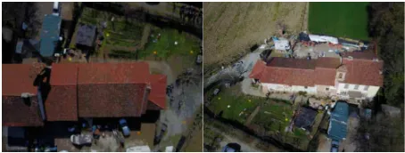
Nowadays the roman church (Figure 1) is private and present several material decays and was selected as test area in the present paper since, as reported before the church was used as part of the teaching activity carried out in the Politecnico di Torino with by the authors and other colleagues that worked in the activity connected to the "Atelier compatibility and sustainability of architectural restoration” for the realization of a complete documentation analysis with the aim of realizing a complete restoration and requalification projects.
Figure 1 Aerial view of the church (left), belfry (right)
3. DATA ACQUISTION
According to the traditional workflow first of all a reference network was realized using GNSS instruments (Global Navigation Satellite System), moreover some artificial target were positioned and measured using the same GNSS and a TS (Total Station) in order to use it for correctly performed the photogrammetric process. Afterwards the flights were carried out using the three UAV platform previously introduced.
3.1 Pre- flights fieldwork
Before the flights planning and the real acquisitions, some traditional topographic measurements have been performed to measure several points in order to provide the correct georeference according to the adjustment performed in the employed photogrammetric software. As usual the surveyed points are used as GCPs (Ground Control Points) or CPs (Check Points), and are positioned homogeneously on the terrain in order to have a sufficient redundancy of measurement for
estimating all the parameters and to check the accuracy of the realized products.
First of all, a simple GNSS network have been realized: three vertices were positioned on the ground (the red points in Figure 2) and measured using static GNSS (two receiver Geomax Zenih 35 were used) for approximately 40 minutes for each baseline. The network was then processed with Leica Geo Office using as reference points two permanent GNSS stations (Savigliano and Mondovì) of the GNSS Piedmont permanent network (https://www.spingnss.it/spiderweb/frmIndex.aspx). Thereafter, using the Total Station the 12 markers previously fixed on the ground were measured together with some paper targets placed on the main walls of the building (in this first step they weren’t used in the processing).
The points on the terrain were surveyed as well with the GNSS receiver in RTK mode in order to have a check on the different accuracy achieved with the two instruments. The discrepancy between the two results were under the centimetre for all the points. According to this value that is included in the expected accuracy of the final products, the coordinate measured by the GNSS were employed for the process.
Figure 2. The topographic network (the three vertices in red) and the target measured for the aerial acquisitions (the 12 points
in blue). On the right some samples of the employed markers.
3.2 COTS employed platforms
For the aerial acquisitions at San Giuliano three different COTS platforms by DJI were employed: the Mavic Pro (Figure 3), the Phantom 4 (Figure 4) and the Phantom 4 Pro (Figure 5). The UAV mentioned above are part of the fleet of Politecnico di Torino that is composed both of mass market and self-built drones. The three platforms are located in different segments of the market, both for price of sell and designated use. The Mavic Pro was the lighter and more portable of the DJI’s products (until the recent launch on the market of the under 300 grams drone of the Chinese company) and was intend as a device for recreational purposes. The Phantom 4 is already more focussed on the community of pilots that use UAV for professional purposes and the Pro version is a substantial upgrade with other flight control sensors and a more performing camera. The general descriptions of these platforms are reported in the following paragraphs while a complete list of specifications can be easily found on the website of the producer: www.dji.com .
3.2.1 Mavic Pro
stabilized video and images. Plus, behind the camera, the drone also has DJI’s ActiveTrack and Optical Flow software, which allow it to track objects and sense obstacles (respectively). The camera shoots in cinematic 4K, snaps 12.7 megapixel stills, and also supports features like burst shooting and exposure bracketing
Figure 3. DJI Mavic Pro. Source: www.dji.com
3.2.2 Phantom 4
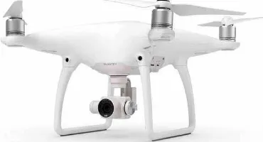
The Phantom 4 (Figure 4) is a quadcopter small UAV, one of the most popular products of DJI. The platform is equipped with a 4K video camera that has a 1/2.3” CMOS sensor, 94-degree field of view, 12.4 MP images 20 mm (35 mm equivalent) with a focus to infinity. The Phantom 4 system weighs 1.38 kg, has a maximum flight time of 28 minutes, and offer the ability to hover and/or collect images or video from nadir and vertical faces as well.
Figure 4. DJI Phantom 4. Source: www.dji.com
3.2.3 Phantom 4 Pro
The Phantom 4 Pro (Figure 5) boasts a number of small but significant improvements comparing to the previous model. Many of the original Phantom 4’s design attributes, electronic components, and features have been ported over to the pro model, while others have been upgraded, and a few new features have been added.
The first important improvement is connected to the new 5-direction obstacle avoidance system, the sensors scan the environment around the platform in order to avoid obstacle. The other fundamental improvement especially for photogrammetric applications is connected to the new camera with a 1” CMOS sensor (four size larger compared to the Phantom 4), this camera is able to acquire 20 Mpixel images and 4K video up to 30 frames per second.
Figure 5. DJI Phantom 4 Pro. Source: www.dji.com
3.3 Flight planning
Five different flights have been performed for each one of the three employed UAVs. Two flights were realized setting a regular grid of flight lines East-West (parallel with the main development of the chapel), two with flight lines North-South (perpendicular with main development of the chapel) and one circular flight (with the centre of the circle defined in the middle of the chapel). Both the East-West and North-South flights were realised with two different camera orientations, nadiral and oblique (≈ 45 degrees). The circular flight was performed with an oblique configuration of the camera. To achieve a good coverage of the chapel and an acceptable overlapping of the images the area of the flights with an oblique configuration of the camera was extended. The flights altitude was set at 40 meters above the ground. All the flights were planned and realised using the Pix 4D capture app directly on the field (Figure 6).
Figure 6. Flight planning using Pix 4D capture.
3.3.1 Troubleshooting
Almost all the 15 flights were realised without problems, with some exceptions: some issues occurred with the Mavic Pro and with the Phantom 4.
Figure 7. Example of blurry images acquired by the Mavic Pro experiences and the good planning of the buffer area before the flight neither people or object were harmed and the aircraft landed safely.
4. DATA PROCESSING
The fifteen datasets were combined and processed together with different modalities and using different software solutions, both commercial and open-source (in this paper we present a comparison about the result obtained by MicMac and Pix4D). Having such a various and complete aerial survey was a great opportunity to evaluate the camera performances of the three platforms and also to make some consideration on the tie points extraction and BBA (Bundle Block Adjustment).
4.1 Combination of dataset
According to the acquired data the available images are related to the following configuration of the flights that follow an flight lines with the centre of the circle in the middle of the site.
The aims of this part of the test was connected to the evaluation of the BBA results connected to the number of images and to the use of GCPs. In order to follow the proposed objective, the datasets were processed according to the next configuration:
A. All the flights (available only for the Phantom 4 and Phantom 4 Pro)
B. Nadiral and Circular (available only for the Phantom 4 and Phantom 4 Pro)
C. Nadiral and Oblique (available for all the platforms) D. Only the two strips of the nadir image (available for
all the platforms)
At the same time a different configuration of Ground Control Points (GCPs) and Check Points (CPs) was employed as well. The blocks were processed using 12 GCPs and 0 CPs (GCP-I),
6 GCPs and 6 CPs (GCP-II) and finally 4 GCPs and 8 CPs (GCP-III). In the next sections, the approach of the employed software and the results are reported.
In a first step of this research another main aim was also to test the accuracy of the on-board GNSS of the three devices and the chance to use the geotagging of the acquired images for the SfM approach. Unfortunately, this was not possible due to some issues related to the recording modality of the GNSS data. After several test, it was not possible to identify which elevation model is used from the sensor for recording GNSS data and as a consequence for the moment this part of the test is not reported in this paper.
4.2 Pix4D Mapper
Pix4D (https://pix4d.com/) was founded in 2011 as a spinoff of the EPFL (École Polytechnique fédérale de Lausanne) and since its establishment the main efforts of the company were focused on the development of software solutions for the processing of images acquired from UAVs. The company is nowadays constantly growing and the proposed software solutions connected with the uses of UAVs are growing as well. Among the different available solutions (that include also the processing of multispectral images for precision agriculture and the integration of data extracted from RGB images in BIM platforms) the Pix4D mapper pro solution was tested and evaluated. Mapper pro follow the standard SfM workflow and is dedicated to the processing of images for the extraction of 3D information and the traditional outputs (point cloud, mesh, DSM and ortophotos).
Pix4D mapper pro works in subsequent steps for the processing of aerial images: initial processing, point cloud densification, and DSM and orthomosaic generation.
Once this first phase of the workflow is completed is possible to move to the second step: the densification process. This part is typically performed by the process known as dense matching and uses the sparse model and initial estimates of camera orientation to reproject individual pixels in real coordinate space. In Pix4D point cloud densification is usually performed using a minimum of three match points for each solved three-dimensional pixel location and the densification of 1/2 scale images Half scale is recommended for use in project areas that do not exhibit very high contrast with many sharp features. In the present project in order to obtain a very accurate 3D point cloud the images were not scaled (1/1). Moreover, the textured mesh could be generated as well at this step. The final step in the Pix4D workflow is the production of DSM and a complete True Orthomosaic (Strecha, 2012). True orthophotos are a common end-product obtained from digital surface models where the aerial images are rectified from a perspective to an orthographic projection using an underlying DSM, the single orthos are automatically clustered in the software.
Figure 8. Cameras position estimated by Pix4D in two of the considered datasets (Mavic Pro left and Phantom 4 Pro Right)
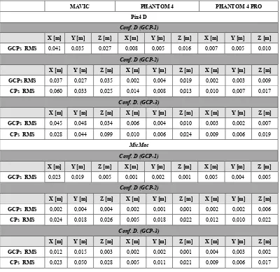
The results of the test performed with Pix4D on the different combinations of dataset are reported in the following Tables 1-2. The result connected to Configuration D (only nadir acquisition) is reported in the last page of the paper.
PHANTOM 4 PHANTOM 4 PRO
Conf A (GCP-I)
X [m] Y [m] Z [m] X [m] Y [m] Z [m]
GCPs
RMS 0.008 0.005 0.013 0.007 0.005 0.011
Conf A (GCP-II)
X [m] Y [m] Z [m] X [m] Y [m] Z [m]
GCPs
RMS 0.008 0.005 0.013 0.007 0.005 0.011 CPs
RMS 0,012 0,009 0,016 0,011 0,009 0,011
Conf A (GCP-III)
X [m] Y [m] Z [m] X [m] Y [m] Z [m]
GCPs
RMS 0,004 0,004 0,008 0,004 0,002 0,006 CPs
RMS 0,011 0,006 0,017 0,009 0,006 0,014
Table 1Achieved RMS in Pix4D according flight Configuration A (all the flights) with a different number of GCPs and CPs
(see section 4.1: GCP-I,II,III)
PHANTOM 4 PHANTOM 4 PRO
Conf B (GCP-I)
X [m] Y [m] Z [m] X [m] Y [m] Z [m]
GCPs
RMS 0.007 0.006 0.013 0.007 0.005 0.012
Conf B (GCP-II)
X [m] Y [m] Z [m] X [m] Y [m] Z [m]
GCPs
RMS 0,002 0,003 0,017 0,002 0,003 0,015 CPs
RMS 0,011 0,010 0,010 0,011 0,009 0,014
Conf B (GCP-III)
X [m] Y [m] Z [m] X [m] Y [m] Z [m]
GCPs
RMS 0,006 0,004 0,006 0,004 0,003 0,013 CPs
RMS 0,008 0,007 0,019 0,010 0,005 0,018
Table 2Achieved RMS in Pix4D according flights Configuration B
4.3 MicMac
MicMac has been developed at the National Institute of Geographic and Forestry Information (IGN) and the National School of Geographic Sciences (ENSG), since 2003 (Deseilligny & Paparoditis 2006). The tools were interfaced in 2005 via an XML framework, allowing the user to freely configure the different parameters and the calculations in every processing stages. In 2007, IGN began to freely distribute MicMac under the CECILB license that is a version of the L-GPL license adapted to the French law. In 2010, the XML interface was replaced by a simplified command line. This evolution contributed to improve the accessibility, and use of the software in the scientific communities, and the common users (Deseilligny & Clery 2011).
The processing steps of MicMac are similar to the other employed software and are usually launched by the terminal. In the below descriptions only the main differences between the employed commercial software and MicMac are reported. The first part is connected to the Tie Points extractions (Tapioca in MicMac) that is quite similar to the commercial solutions; in this part of the workflow MicMac use the Vedaldi (Vedaldi, 2007) modified version of the well-known SIFT (Scale Invariant Feature Transform) developed by Lowe (Lowe, 2004). The strategy that could be used are different and in the study the option All was used; this option allow to extract the tie points between all the pairs of the photogrammetric block using a predefined number of pixel for each image.
distortion (r3, r5 ). Despite the use of this simplified model some images were not oriented as well (especially the oblique one). In Figure 9 two screenshots of the oriented images in MicMac (Phantom 4 left and Mavic right).
Figure 9 Camera pose of two oriented dataset using MicMAc (Phantom 4 left, Mavic right)
The next steps are first of all connected to the use of real measurements that could be inserted in MicMac as GCPs or CPs using a graphic interface. Moreover, after this step that probably is like in the other software very time spending, the final BBA was computed using the MicMac tool Campari. MicMac solves the BBA with the Levenberg-Marquardt (LM) method.
The LM algorithm is an iterative technique that locates a local minimum of a multivariate function that is expressed as the sum of squares of several non-linear, real-valued functions. LM can be thought of as a combination of steepest descent and the Gauss-Newton method. When the current solution is far from a local minimum, the algorithm behaves like a steepest descent method: slow, but guaranteed to converge. When the current solution is close to a local minimum, it becomes a Gauss-Newton method and exhibits fast convergence (Madsen et al., 2004).
A range of different parameters are allowed in the adjustment such us Tie Points, GCPs, CPs etc.
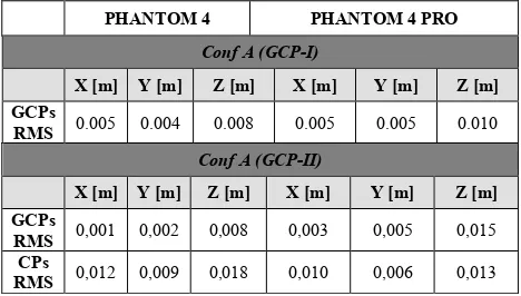
The weighting of the observation is realized first of all by the Gauss-Markov approach with a priori Standard Deviation, furthermore during the BBA the approach give more credibility to observations that are close to the estimated model, and contrary, limiting the influence of observations with high residuals (and where the result is not consistent delete the point). In the following tables the results of the different flights combination using different number of GCPs and CPs with the different employed platform are reported. In order to summarize the results only the X, Y, and Z RMS are reported (in the following table 3 and 4 are showed the results of Conf. A and B). At the end of the paper the results of Configuration D that include the dataset of Mavic are showed.
PHANTOM 4 PHANTOM 4 PRO
Conf A (GCP-I)
X [m] Y [m] Z [m] X [m] Y [m] Z [m]
GCPs
RMS 0.005 0.004 0.008 0.005 0.005 0.010
Conf A (GCP-II)
X [m] Y [m] Z [m] X [m] Y [m] Z [m]
GCPs
RMS 0,001 0,002 0,008 0,003 0,005 0,015 CPs
RMS 0,012 0,009 0,018 0,010 0,006 0,013
Conf A (GCP-III)
X [m] Y [m] Z [m] X [m] Y [m] Z [m]
GCPs
RMS 0,005 0,002 0,005 0,002 0,003 0,006 CPs
RMS 0,009 0,007 0,017 0,010 0,007 0,017
Table 3Achieved RMS with MicMac according to flight Configuration A
PHANTOM 4 PHANTOM 4 PRO
Conf B (GCP-I)
X [m] Y [m] Z [m] X [m] Y [m] Z [m]
GCPs
RMS 0.005 0.004 0.008 0.005 0.005 0.010
Conf B (GCP-II)
X [m] Y [m] Z [m] X [m] Y [m] Z [m]
GCPs
RMS 0,001 0,002 0,007 0,003 0,003 0,007 CPs
RMS 0,007 0,010 0,018 0,009 0,009 0,016
Conf B (GCP-III)
X [m] Y [m] Z [m] X [m] Y [m] Z [m]
GCPs
RMS 0,005 0,003 0,004 0,003 0,003 0,005 CPs
RMS 0,010 0,007 0,017 0,010 0,006 0,016
Table 4Achieved RMS in MicMac according flights Configuration B
5. DATA ANALYSES
As is possible to notice, according to the achieved errors (Table 1 and Table 3), the results are very accurate and surely the data could be used for architectural large-scale documentation proposal. Similar results were obtained using configuration A and B as is reported in the previous Table1,2,3,4 for both the employed software packages. From this test as a consequence is possible to state that in order to obtain a correct accuracy of the block use a combination of nadir images (two perpendicular strips) with a circular oblique acquisition could be a good solution for optimizing the time for UAV data collection and GCPs survey.
The importance of the oblique images is furthermore confirmed by the results reported in Table 5 were is possible to notice that the influence of the oblique images improve the quality of the block and moreover allow to decrease the number of GCPs for the realization of the BBA since the results of using a few number of GCPs (Table 2 and Table 3 GCP-III) are totally comparable to the use of a large number of GCPs (Table 2 and Table 3 GCP-I). These results are confirmed by statistical simulation (Dall’Asta et al., 2015; Santise, 2016; Luhmann, 2011) and as well by several previous test performed by the authors (Chiabrando et al., 2017; Aicardi, 2017).
that could be one of the main reason of those poor accurate obtained results.
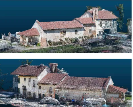
6. CONCLUSION AND FURTHER ACTIVITIES According to the obtained results is possible to state that nowadays the connection between COTS UAV and photogrammetric accuracy is fulfilled. The use of those platform could be considered today a standard for metric survey and 3D modelling purpose as well. Some open issues are however under investigation like the camera calibration of the employed sensors, the use of on board GNSS data for direct photogrammetry purpose and finally the accuracy evaluation of video frames for photogrammetric purpose. Concerning the software, in the present paper are presented two solutions one commercial and one open source. Pix4D allow to obtain very accurate results and is not time spending but since it is commercial is difficult to interact with the parameters (for instance is not possible to change the camera calibration approach). On the other hand, MicMac is totally open and allow to interact in all the processing steps with the use of hundreds of parameters with unfortunately a lack of graphic interface that probably will be developed in the next future. The achieved results are totally comparable but with MicMac a deeper knowledge of the photogrammetric methodology is needed combined with a basic knowledge of Linux. Further test are on-going on the Church of San Giuliano in order to compare the obtained point-clouds and 3D model with an accurate 3D survey performed by LiDAR instruments. In Figure 10 two views of the dense cloud of the church.
Figure 10 Two view of the achieved dense point cloud of the San Giuliano Church
ACKNOWLEDGEMENTS
A special acknowledgement to Paolo Maschio for helping the authors during the survey operation in Savigliano.
REFERENCES
Aicardi, I., 2017. UAVs for spatial data acquisition. Sensors evaluation, flight design and planning, multi-temporal solutions. PhD Thesis Politecnico di Torino.
Aicardi, I., Chiabrando, F., Grasso, N., Lingua, A. M., Noardo, F., Spanò, A., 2016. UAV photogrammetry with oblique images: First analysis on data acquisition and processing.
International Archives of the Photogrammetry, Remote Sensing and Spatial Information Sciences, Volume XLI-B1, pp. 835-842.
Bendea, H., Chiabrando, F., Tonolo, F. G., Marenchino, D., 2007. Mapping of archaeological areas using a low-cost UAV. The Augusta Bagiennorum test site. In Proceedings of the XXI International CIPA Symposium, pp. 1-6.
Chiabrando, F., Lingua, A., Maschio, P., Teppati Losè, L., 2017. The influence of flight planning and camera orientation in UAVs photogrammetry. A test in the area of Rocca San Silvestro (LI), Tuscany. International Archives of Photogrammetry, Remote Sensing and Spatial Information Sciences, Vol. XLII-2/W3, pp. 163-170.
Dall'Asta, E., Thoeni, K., Santise, M., Forlani, G., Giacomini, A., Roncella, R., 2015. Network design and quality checks in automatic orientation of close-range photogrammetric blocks. Sensors, 15(4), 7985-8008.
Förstner, W., & Wrobel, B. (2016). Photogrammetric computer vision. Chapter robust estimation and outlier detection. Springer, Berlin, 141-159.
Fraser, C., 1997, Digital camera self-calibration, ISPRS Journal of Photogrammetry and Remote Sensing, vol. 52, issue 4, pp. 149-159.
Goodrich, M. A., Morse, B. S., Gerhardt, D., Cooper, J. L., Quigley, M., Adams, J. A., & Humphrey, C.,2008. Supporting wilderness search and rescue using a camera- equipped mini UAV. Journal of Field Robotics, 25(1- 2), pp. 89-110.
Kerle, N., Fernandez Galarreta, J., Gerke, M., 2014. Urban structural damage assessment with oblique UAV imagery, object-based image analysis and semantic reasoning. Proc., 35th Asian conference on remote sensing.
Lowe, D. G., 2004. Distinctive image features from scale-invariant keypoints. International journal of computer vision, 60(2), pp.91-110.
Luhmann, T., 2011. 3D imaging: how to achieve highest accuracy. SPIE Optical Metrology, pp. 808502-808502. Madsen, K., Nielsen, H., Tinglef, O.,2004. Methods for Non-Linear Least Squares Problems. Technical University of Denmark, 2004. Lecture notes.
Nex, F., Remondino, F., 2014. UAV for 3D mapping applications: a review. Applied Geomatics, 6(1), pp. 1-15.
Pierrot-Deseilligny, M., Paparoditis, N., 2006. A multiresolution and optimization-based image matching approach: An application to surface reconstruction from spot5-hrs stereo imagery. Archives of Photogrammetry, Remote Sensing and Spatial Information Sciences 36, Vol. 1/W41.
Pierrot-Deseilligny, M., Clery, I., 2011. Apero, an open source bundle adjustment software for automatic calibration and orientation of set of images. International Archives of the Photogrammetry, Remote Sensing and Spatial Information Sciences, Vol. XXXVIII-5/W1, pp. 269-276.
Archives of the Photogrammetry, Remote Sensing and Spatial Information Sciences, Volume XL-1/W1, pp 299-304.
Santise, M., 2016. UAS Photogrammetric Blocks: Accuracy, Georeferencing and Control. Ph.D. Thesis, University of Parma
Sauerbier, M., Eisenbeiss, H., 2010. UAVs for the documentation of archaeological excavations. International Archives of Photogrammetry, Remote Sensing and Spatial Information Sciences, Vol. XXXVIIIPart 5, pp. 526-531. Strecha, C., 2014. The ray Cloud–a vision beyond the point cloud. In FIG Congress.
Strecha, C., Küng, O., & Fua, P., 2012. Automatic mapping from ultra-light uav imagery. In EuroCOW 2012.
Turletti, C., 1883. Storia di Savigliano, VOL. II ,pp. 234-243, Edizione Anastatica, Savigliano 1883
Vedaldi, A., An open implementation of the SIFT detector and descriptor, A., UCLA CSD, 2007
Virone, G., Lingua, A. M., Piras, M., Cina, A., Perini, F., Monari, J,Tascone, R., 2014. Antenna pattern verification system based on a micro unmanned aerial vehicle (UAV). IEEE Antennas and Wireless Propagation Letters, 13, pp. 169-172.
MAVIC PHANTOM 4 PHANTOM 4 PRO
Pix4 D
Conf. D (GCP-1)
X [m] Y [m] Z [m] X [m] Y [m] Z [m] X [m] Y [m] Z [m]
GCPs RMS 0,041 0,035 0,027 0,008 0,005 0,016 0,007 0,005 0,010
Conf. D (GCP-2)
X [m] Y [m] Z [m] X [m] Y [m] Z [m] X [m] Y [m] Z [m]
GCPs RMS 0,037 0,027 0,035 0,002 0,004 0,019 0,002 0,003 0,009
CPs RMS 0,060 0,033 0,025 0,014 0,008 0,013 0,010 0,007 0,017
Conf. D. (GCP-3)
X [m] Y [m] Z [m] X [m] Y [m] Z [m] X [m] Y [m] Z [m]
GCPs RMS 0,045 0,048 0,034 0,006 0,004 0,010 0,003 0,002 0,007
CPs RMS 0,028 0,044 0,099 0,010 0,006 0,024 0,009 0,006 0,019
MicMac
Conf. D (GCP-1)
X [m] Y [m] Z [m] X [m] Y [m] Z [m] X [m] Y [m] Z [m]
GCPs RMS 0,023 0,019 0,005 0,001 0,002 0,001 0,005 0,004 0,005
Conf. D (GCP-2)
X [m] Y [m] Z [m] X [m] Y [m] Z [m] X [m] Y [m] Z [m]
GCPs RMS 0,002 0,004 0,004 0,002 0,001 0,001 0,002 0,002 0,006
CPs RMS 0,024 0,018 0,026 0,005 0,018 0,022 0,012 0,010 0,022
Conf. D. (GCP-3)
X [m] Y [m] Z [m] X [m] Y [m] Z [m] X [m] Y [m] Z [m]
GCPs RMS 0,012 0,015 0,003 0,002 0,002 0,001 0,004 0,003 0,002
CPs RMS 0,023 0,050 0,028 0,005 0,011 0,021 0,009 0,006 0,017