Pointing Angle Calibration of ZY3-02 Satellite Laser Altimeter using Terrain Matching
Guoyuan.Li a,b,c, *, Xinming.Tang a,b,c,Xiaoming.Gao a,b,c, JiaPeng Huang a,d, Jiyi Chen a,c,Jing Lu a,ca Satellite Surveying and Mapping Application Center, NASG, Beijing, China - (ligy, txm, gaoxm,chenjy,luj)@sasmac.cn. b School of Resource and Environmental Sciences, Wuhan University, Wuhan, China
c Jiangsu Center for Collaborative Innovation in Geographical Information Resource Development and Application, Nanjing, China d School of Geomatics, Liaoning Technical University, Liaoning Fuxin 123000,[email protected]
EuroCOW, WG I/4
KEY WORDS: ZY3-02; Satellite Laser Altimeter; Geometric Calibration; Terrain Matching; GLAS
ABSTRACT:
After GLAS (Geo-science Laser Altimeter System) loaded on the ICESat (Ice Cloud and land Elevation Satellite), satellite laser altimeter attracts more and more attention. ZY3-02 equipped with the Chinese first satellite laser altimeter has been successfully launched on 30th May, 2016. The geometric calibration is an important step for the laser data processing and application. The method to calculate the laser pointing angle error based on existed reference terrain data is proposed in this paper. The public version terrain data, such as 90m-SRTM and 30m-AW3D30, can be used to estimate the pointing angle of laser altimeter. The GLAS data with simulated pointing error and actual ZY3-02 laser altimetry data is experimented to validate the algorithm. The conclusion will be useful for the future domestic satellite laser altimeter.
* Corresponding author: [email protected] 1. INTRODUCTION
ZY3-02 satellitewas successfully launched on 30th May, 2016, which has equipped with the first satellite laser altimeter of China for earth observing. The laser altimeter on the ZY3-02 satellite was designed to validate the acquisition of the global high accuracy elevation control points and the possibility of stereo images accuracy improvement without GCPs (Ground Control Points) (Tang, et al, 2016).. The on-orbit geometric calibration of satellite laser altimeter is a basic and indispensible for the effective application of altimetry data, especially in order to be used as control points. Some researchers presented variety geometric calibration methods for GLAS (Geo-science Laser Altimeter System) loaded on the ICESat (Ice Cloud and land Elevation Satellite) (Rowlands et al, 2000; Luthcke et al, 2000, 2002; Schutz, 2001; Martin et al, 2005; Sirota et al, 2005; Magruder et al, 2005), which contained maneuvering flight on the ocean, infrared imaging the ground footprint of GLAS laser points during the night , laying the ground detectors to capture the laser signal or waveform matching. According to the above calibration result, the accuracy of GLAS laser pointing angle could reach to better than 1.5", and the ranging accuracy was better than 10cm, which ensured the absolute elevation accuracy of 15cm on the flat terrain finally (Schutz et al, 2005; Wang et al, 2011). For ZY3-02 satellite laser altimeter, the pointing angle has some deviation between the truth and the measurement in the laboratory, which can not meet the demand of high accuracy laser data processing and the field experiment of laying ground detectors whose position should has little error calculated by the laser pointing angle value. So, the on-orbit geometric calibration to improve the accuracy of the pointing angle is urgent and very important for the next step of data processing or field experiment.
As early as a few years ago, scholars used the public version or the existed version of terrain reference data to evaluate or compensate the satellite image orientation parameters. Jeong et al (2012) used 90m grid global DEM to orient the high resolution satellite images and improve the images geometric accuracy. Kim, et al (2011) used the 3 dimensional similarity transform to compensate the attitude of the satellite and the
orbit parameter based DEM matching and rigorous sensor model, and improved the mapping accuracy of high resolution satellite image without GCPs. Zhou, et al (2016) pointed out that using SRTM 90m data can effectively improve ZY3 images without the control points, especially with better elevation accuracy. Moreover, matching the existed terrain data for orientation or position in cruise missile, underwater position and other fields have also been widely used( Rao et al, 2016). Affected by the measurement conditions and the precision of the instrument, gravity environment, vibration and other factors, the pointing angle error of ZY3-02 satellite laser altimeter is non-ignorable, which has distinct effect on both the planimetry and the elevation accuracy of the ground footprint. This paper proposes the ZY3-02 satellite laser pointing angle coarse calibration method based on the terrain matching, and the fine calibration needs other method, such as the ground detectors with high accuracy position measured by RTK-GPS. The simulated experiment derived from GLAS data and the true ZY3-02 satellite laser altimetry data is carried out and validated. In Section 2, the methodology is presented, and the experiment and analysis is implemented in Section 3. At last, the conclusion and future research work is remarked in Section 4.
2. METHODOLOGY
Considering that the satellite laser altimeter footprint points should be in agreement with the actual terrain profile, this paper uses the terrain matching to estimate the laser pointing angle, achieve the systematic deviation of laser pointing angle without other data and predict the initial footprint position for future field experiment effectively. The satellite laser altimetry data is a series of discrete points located on the ground along the track of the satellite and the coordinates of laser footprint points can be expressed as Eq.1, according to the referenced paper about ZY3-02 satellite (Tang, et al, 2016).
( , , )
(
,
, , )
i i
p x y z
f
d
(1) ( , , )x y z is the coordinate of the laser footprint pints.(
i,
d
, , )
is the laser ranging, ranging deviation and laser pointing angle. when the distance from satellite to the ground isfixed by the laser ranging value, then different distance deviation and pointing angle can obtain different three-dimensional points groups. Among these points groups, there is only one group can fit the true terrain for the best, and the laser pointing angle of this points group is the best, which is the closest value to the truth.
If we define the collection of these discrete points set as P, then there should be a set of actual terrain Q, P=Q. P and Q are described in Eq.(2) and Eq.(3), respectively. It means that there is a group value of ranging deviation d
and pointing angleIn theory, if all errors has been eliminated, there should be P=Q. But the random error of laser altimetry data, then the set of P
Figure 1. Satellite laser altimeter geometric calibration based on terrain matching
How to measure the similarity of set P and Q becomes the focus. In the aspect of similarity measurement, it has the the correlation coefficient, the minimum distance, the minimum square of the difference and so on. The most common is the correlation coefficient, which is the standardized covariance function (Zhang, et al., 2009), and it has been widely used in the automatic matching of photogrammetric images. But considering that the correlation coefficient is related with a lot of calculation about the mean and variance of the data, this paper selects the minimum square of the elevation distance between the laser points set
P
and the actual terrain set Qas the similarity. Which is described in Eq.(4).2
The topography within the laser footprint will introduce error to the range and then the elevation error of the laser point (Li et al,2017). Therefore, in order to ensure the reliability and consistency of the laser ranging accuracy in the calculation of foot printing, the footprint terrain of ZY3-02 satellite laser altimeter should be selected to ensure the height accuracy. According to the given referenced terrain data, the topographic features can be described using the slope
S
and the roughnessWhere,
S
X,S
Yis the slope angle of the laser footprint along and across the satellite track, respectively.For ZY3-02 satellite, we select the laser footprint points on the slope less than 2º and the roughness less than 1.0m to calculate the elevation distance between points set P and Q. Once the pointing angle
, is changed, we can get different elevation distance value, and the minimum value among them is the coarse pointing angle. Then, the mean value of the elevation difference between the laser point and the reference terrain can be regarded as the initial value ofd
as the systematic error. It is clear that the inherent error and grid size of the reference terrain can influence the calculated result of the laser pointing angle, which has been discussed in the next section.3. EXPERIMENTAL AND ANALYSIS
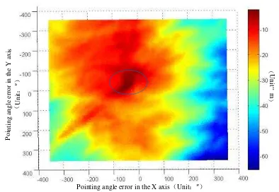
In order to verify whether using the different pointing angle, then the sum of the elevation distance square between the laser footprint points and reference terrain points exist a minimum value, and ZY3-02 satellite laser altimetry data with different pointing angle error is simulated, and the three-dimension map is displayed in Figure 2. Where, X, Y axis represents the laser pointing angle error, the Z axis represents the elevation error of the laser footprint points. Obviously, there is a minimize error vertex in Figure 2, which can be further verified in Figure 3 which means viewing Figure 2 from the up, and the circle contains the closest pointing angle error with the actual value. Meanwhile, the square sum of the laser footprint elevation error is the minimum. Therefore, by setting the change step value of the laser pointing angle, the pointing angle estimation according to the Eq.(4) can be found.
Pointing angle error in the X axis
Unit:″ Pointing angle e
Figure 2. Elevation error distribution of laser foot prints with different pointing error
Pointing angle error in the X axis Unit:″
Pointi
Figure 3. Elevation error distribution of laser foot prints with different pointing error viewing from the Up
The paper chooses the ICESat/GLAS actual data, simulates different pointing angle error, and then estimates the error based on the terrain matching and compares the actual and simulated angle value to validate the method. During the experiment, the 30m ALOS-AW3D30 and 90m SRTM data are selected as prior reference terrain data, and the actual GLAS altimetry data on 25th March, 2009 derived from NSIDC (National Snow and Ice Data Center) is viewed as experimental data, which is illustrated in Figure 4.
101.0 102.0 103.0 104.0 105.0 106.0 107.0 35.0
36.0 37.0 38.0 39.0 40.0
Longitude Latitude
Elevation:m GLAS Point
N
Figure 4. The distribution of GLAS laser footprint points During the experiment, the GLAS laser pointing angle in the X and Y axes is simulated to add 10 ", 20", 30 ", 50", 70 "and 120" error. And the orbit height of ICESat is about 600km, then 1" pointing angle deviation can cause about 2.9m error on the ground, so the positioning error caused by the simulated angle error can be approximately to 30m~360m. At the same time, the pointing angle error will cause the elevation error, as shown in Figure 5, the original GLAS data is the red curve, the blue represents the terrain data, and the green represents the GLAS
simulated data added pointing angle error. Obviously, the original GLAS data is almost in accordence with the terrain data, and the simulated data derived from pointing error has large deviation with the real terrain in the elevation direction.
The ID of points along the track
Ele
vati
on value
Unit
:
m
Simulated data Reference terrain Original GLAS data
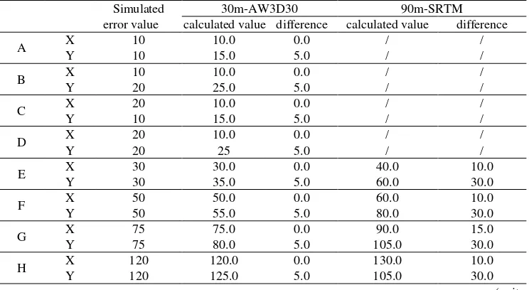
Figure 5. The profile of original GLAS data, reference terrain and simulated data derived from pointing error The grid size of reference terrain data AW3D30 is 30m, and SRTM is 90m, so the corresponding laser pointing angle is about 10" and 30". In the experiment, when there are 10", 20", 30", 50", 75 "and 120" different pointing angle error, while the SRTM grid is approximately equal to 30", so the pointing angle error less than 30" only using AW3D30 30m terrain data. And when the simulated error is more than 30", the two kinds of terrain data are compared, and the result is shown in Table 1.
Table 1. Simulated GLAS laser pointing angle calculation based on terrain matching Simulated
error value
30m-AW3D30 90m-SRTM
calculated value difference calculated value difference
A X 10 10.0 0.0 / /
Y 10 15.0 5.0 / /
B X 10 10.0 0.0 / /
Y 20 25.0 5.0 / /
C X 20 10.0 0.0 / /
Y 10 15.0 5.0 / /
D X 20 10.0 0.0 / /
Y 20 25 5.0 / /
E X 30 30.0 0.0 40.0 10.0
Y 30 35.0 5.0 60.0 30.0
F X 50 50.0 0.0 60.0 10.0
Y 50 55.0 5.0 80.0 30.0
G X 75 75.0 0.0 90.0 15.0
Y 75 80.0 5.0 105.0 30.0
H X 120 120.0 0.0 130.0 10.0
Y 120 125.0 5.0 105.0 30.0
(unit:″) What’s more, the laser repetition rate of GLAS is 40Hz while
the ZY3-02 satellite laser altimeter is only 2Hz, and the distance between the neighbouring points is 170m and 3.5km for the two satellites respectively. In order to eliminate the calculation error caused by different density, GLAS laser data is sparsed from 20 points to 2 points, makes the spacing of GLAS equal to the ZY3-02 satellite, and then simulates and calculates the pointing angle error, the result is shown in Table 2. It is clear that terrain matching for the simulation data of GLAS still can be used to estimate the laser pointing angle error even if they are sparsed,
but the error is bigger than no-spared. Using primary data, the deviation value of the Y axis is about 5″ when the AW3D30 is used, and the deviation value will increase to 15″ after the GLAS points are sparsed, it shows that the density of laser points has an effect on the accuracy of the terrain matching calculation.
Based on terrain matching, we choose seven tracks of actual laser altimetry data from the ZY3-02 satellite to calculate the laser pointing error before the field calibration experiment. And the experimental data of ZY3-02 laser data and terrain reference
data of the same area is described in Table 3. There are SRTM with 90m grid, ZY3-DSM with 25m grid, and ALOS-AW3D30 with 30m grid, respectively. And the DSM data with 5m grid size along the 656th track is collected. The terrain matching
using the reference terrain data is carried out to calculate the pointing angle error of these seven tracks laser altimetry data. The result is shown in Table 4.
Table 2. Statistical table of pointing angle error calculated by sparsed GLAS laser data
Group axial Simulated error value
30m-AW3D30 90m-SRTM
calculated value difference calculated value difference
A X 10 5.0 -5.0 / /
Y 10 25.0 15.0 / /
B X 10 5.0 -5.0 / /
Y 20 35.0 15.0 / /
C X 20 15.0 -5.0 / /
Y 10 25.0 15.0 / /
D X 20 15.0 -5.0 / /
Y 20 35.0 15.0 / /
E X 30 25.0 -5.0 40.0 10.0
Y 30 45.0 15.0 60.0 30.0
F X 50 55.0 0.0 60.0 10.0
Y 50 85.0 5.0 90.0 40.0
G X 75 80.0 -5.0 85.0 10.0
Y 75 90.0 15.0 110.0 35.0
H X 120 115.0 -5.0 130.0 10.0
Y 120 135.0 15.0 150.0 30.0
(unit:″) Table 3. The terrain matching experimental data of ZY3-02 satellite
Track
number acquisited time
Reference DSM
90m SRTM 30m AW3D30 25m ZY3-DSM 5m DSM
382 24th June √ √ √
656 12th July √ √ √ √
914 29th July √ √ √
915 29th July √ √
929 30th July √ √ √
944 31st July √ √ √
945 31st July √ √ √
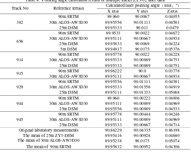
Table 4. Pointing angle calibration results of multiple tracks ZY3-02 laser data
Track No Reference terrain Calculated laser pointing angle unit:º
X axis Y axis Z axis
382
90m SRTM 89.960 90.0067 0.04055
30m ALOS-AW3D30 89.95556 90.01111 0.04581
25m DSM 89.95333 90.011 0.0479
656
90m SRTM 89.9533 90.0022 0.04672
30m ALOS-AW3D30 89.95111 90.00667 0.04934
25m DEM 89.95833 90.0069 0.04224
5m DSM 89.94917 90.0175 0.05376
914
90m SRTM 89.95778 90.0022 0.04228
30m ALOS-AW3D30 89.95333 90.00889 0.04751
25m DSM 89.95333 90.00889 0.04751
915 90m SRTM 89.96222 90.0 0.03778
30m ALOS-AW3D30 89.95111 90.00667 0.04934
929
90m SRTM 89.95556 90.01111 0.04581
30m ALOS-AW3D30 89.95333 90.01556 0.04919
25m DSM 89.95111 90.01333 0.05068
944
90m SRTM 89.960 90.00222 0.04006
30m ALOS-AW3D30 89.95111 90.00889 0.04969
25m DSM 89.95556 90.00889 0.04533
945
90m SRTM 89.95778 90.00444 0.04246
30m ALOS-AW3D30 89.95111 90.00889 0.04969
25m DSM 89.95333 90.00667 0.04714
Original laboratory measurements 90.86229 90.04335 0.86198
The mean of 25m ZY3-DSM 89.95416 90.00928 0.04680
The mean of 30m ALOS-AW3D30 89.95238 90.0175 0.05074
The mean of 90m SRTM 89.95832 90.00952 0.04306
Based on the experimental result of the above, the difference between the pointing angle and the average value of multiple
tracks data using the same reference terrain is calculated. The statistical results are shown in Table 5.
Table 5. The difference between pointing angle and average value using same reference terrain
Reference terrain
The difference between the maximum and the average of the pointing angle(unit:″)
The difference between the minimum and the mean of the pointing angle(unit:″) based on the terrain matching, and the effect of reference terrain data with different grid sizes, we check the geo-location result SRTM with 90m grid size, the mean value using AW3D30 with 30m grid size, the mean value using DSM with 30m grid size, 5m-DSM and the total mean of all, are compared with the true
location. And the planimetric error is illustrated in Table 6. Before the calibration, the planimetric error is about 8km using the original laser pointing angle, which confirms the indispensability of the calibration. After implementing the pointing angle calibration based on the terrain matching, the plane accuracy has improved dramatically, and when the reference terrain with smaller grid size is used, the result can be better. For instance, the accuracy is about 86m using the pointing angle calibrated by the 90m-SRTM, while the result can reach to 28.8m by the 5m-DSM, and the 28.8m is just equivalent to 10" error of the pointing angle.
Table 6. The position error of the ground detector using the pointing angle derived from DSM with different grid
The point of E2818 Planimetry error (unit:m) The east The north The plane Original pointing angle 1967.73 7802.81 8047.11 The mean of 90m-SRTM pointing angle -55.36 66.25 86.34 The mean of 30m-AW3D30 pointing angle -56.29 27.18 62.51 The mean of 25m-DSM pointing angle -65.39 30.73 72.26
The mean of pointing angle -56.01 44.47 71.51
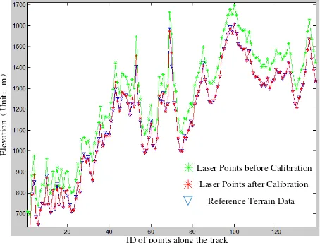
The mean of 5m-DSM pointing angle -4.01 -27.99 28.28 Moreover, the elevation result before and after the calibration
based on the terrain matching is compared using the Track 382 of ZY3-02 satellite laser altimetry data. The profile along the track is illustrated in Figure 6. The green and red points represent the result before and after the calibration, respectively. And the blue points represent the reference terrain data. It is obvious that the laser footprint point elevation profile after calibration can achieve good results and be accordance with the actual terrain profile.
Figure 6. Track 382 laser footprint points and reference terrain data before and after pointing angle calibration
4. CONCLUSION
In this paper, the laser altimeter pointing angle calibration method is proposed. And the simulated GLAS data and actual ZY3-02 laser altimeter data is implemented. It can be seen from the experimental result, using the reference terrain data and
terrain matching can effectively estimate the laser pointing angle deviation of satellite laser altimeter.
According to GLAS data with simulated error, the accuracy depends on the density of laser points, grid size and the elevation accuracy of the priori terrain data. The accuracy of pointing angle can reach to 0.5- 1.5 times grid size of the terrain data, and the result derived from AW3D30 will be better than 90m-SRTM. And when the laser footprint points are denser, the pointing angle calibrated result will be better.
For ZY3-02 satellite, the original laser pointing angle has deviation with the actual value, which will introduce geo-location error about 8km. And the calibration based on terrain matching can improve the pointing and the positioning accuracy effectively. After using the 5m-DSM as reference terrain, the accuracy of the laser footprint points can reach to 28m, and it will be useful and helpful for the next field experiment to lay the ground detectors for detail calibration. And the method is stable for different tracks laser data, which can be reduced from Table 4, in which the result is almost the same even if the track or the terrain data is different. It is also validated by the GLAS data experimental result.
In the next several years, the GF-7 satellite and Terrestrial Ecosystem Biomass Monitoring satellite will be launched and loaded the laser altimeters, which also need the calibration for accurate pointing angle. The method based on terrain matching in this paper can estimate the laser pointing and eliminate blunder effectively. But detail calibration about the laser altimeter still needs further research for accurate mapping.
ACKNOWLEDGEMENTS
This work was supported by the Special Fund for High Resolution Images Surveying and Mapping Application System ((Grant No.AH1601-8) and the National Fund for Basic Surveying and Mapping (Grant No. 2017KJ0204). The authors
also thank the National Snow and Ice Data Center (NSIDC) for providing the GLAS data and anonymous reviews for their constructive comments and suggestions.
REFERENCES
Filin S. 2006. Calibration of spaceborne laser Altimeters an algorithm and the site selection problem [J]. IEEE Transactions on Geoscience & Remote Sensing, 44(6):1484-1492.
Jeong J, Kim T. 2012. The Use of Existing Global Elevation Dataset for Absolute Orientation of High Resolution Image Without GCPs[J]. ISPRS - International Archives of the Photogrammetry, Remote Sensing and Spatial Information Sciences, XXXIX-B4:287-290.
Kim T, Jeong J. 2011. DEM matching for bias compensation of rigorous pushbroom sensor models [J]. Isprs Journal of Photogrammetry & Remote Sensing, 66(66):692-699.
Li G Y, Tang X M, Zhang C Y, et al. 2017. Multi-criteria Constraint Algorithm for Selecting ICESat/GLAS Data as Elevation Control Points [J]. Journal of Remote Sensing, 21(1):96-104.
Luthcke S B, Rowlands D D, MccarthyJ J, et al.2000. Spaceborne Laser Altimeter Pointing Bias Calibration from Range Residual Analysis [J]. Journal of Spacecraft & Rockets, 37(3):374-384.
Luthcke S B, Carabajal C C, Rowlands D D. 2002. Enhanced geolocation of spaceborne laser altimeter surface returns: parameter calibration from the simultaneous reduction of altimeter range and navigation tracking data [J].Journal of Geodynamics, (34): 447-475.
Martin C F, Thomas R H, Krabill W B, et al. ICESat range and mounting bias estimation over precisely-surveyed terrain[J]. Geophysical Research Letters, 2005, 32(21):242-257.
Magruder L, Silverberg E, Webb C, et al. 2005. In situ timing and pointing verification of the ICESat altimeter using a ground based system[J].Geophysical Research Letters, 322(21): 365-370.
Rao J, Zhang J Y, Fen W. 2016. Research on sequence of terrain bathymetry slope in underwater terrain matching navigation [J]. Journal of Huazhong University of Science and Technology, 2016, 2:118-122.
Rowlands D D, Carabajal C C, Luthcke S B,et al. 2000. Satellite Laser Altimetry On-Orbit Calibration Techniques for Precise Geo-location [J]. Review of Laser Engineering, 28(12): 796-803.
Schutz B E. 2001. GLAS Altimeter Post-Launch Calibration/ Validation Plan [R].
Schutz B E, Zwally H, Shuman C, et al. 2005. Overview of the ICESat Mission. Geophysical Research Letters, 32(21):97-116.
Sirota J M, Bae S, Millar P, et al. 2005. The transmitter pointing determination in the Geo-science Laser Altimeter System [J]. Geophysical Research Letters, 322(22): 231-238.
Tang X M, Li G Y, Gao X M, et al. 2016. The Rigorous Geometric Model of Satellite Laser Altimeter and Preliminarily
Accuracy Validation [J]. Acta Geodaetica et Cartographica Sinica, 45(10): 1182-1191.
Wang X, Cheng X, Gong, P., et al, 2011. Earth science applications of ICESat/GLAS: a review. Int. J. Remote Sens. 32(23), 8837–8864.
Zhang J Q, Pan L, Wang S G. 2009. Photogrammetry [M]. The Second Editor. Wuhan: Wuhan University Press.
Zhou P, Tang X M, Cao N, et al. 2016. SRTM-aided Stereo Image Block Adjustment without Ground Control Points [J]. Acta Geodaetica et Cartographica Sinica, 45(11): 1318-1327.