IPS – A SYSTEM FOR REAL-TIME NAVIGATION AND 3D MODELING
Denis Grießbach, Dirk Baumbach, Anko Börner, Maximilian Buder, Ines Ernst, Eugen Funk, Jürgen Wohlfeil and Sergey Zuev
German Aerospace Center (DLR) Optical Information Systems Robotics and Mechatronics Center (RMS) Rutherfordstrasse 2, 12489 Berlin, Germany
Commission V/1
KEY WORDS:Multisensor, Vision, Navigation, Fusion, Robotics
ABSTRACT:
Reliable navigation and 3D modeling is a necessary requirement for any autonomous system in real world scenarios. German Aerospace Center (DLR) developed a system providing precise information about local position and orientation of a mobile platform as well as three-dimensional information about its environment in real-time. This system, called Integral Positioning System (IPS) can be applied for indoor environments and outdoor environments.
To achieve high precision, reliability, integrity and availability a multi-sensor approach was chosen. The important role of sensor data synchronization, system calibration and spatial referencing is emphasized because the data from several sensors has to be fused using a Kalman filter. A hardware operating system (HW-OS) is presented, that facilitates the low-level integration of different interfaces. The benefit of this approach is an increased precision of synchronization at the expense of additional engineering costs. It will be shown that the additional effort is leveraged by the new design concept since the HW-OS methodology allows a proven, flexible and fast design process, a high re-usability of common components and consequently a higher reliability within the low-level sensor fusion.
Another main focus of the paper is on IPS software. The DLR developed, implemented and tested a flexible and extensible software concept for data grabbing, efficient data handling, data preprocessing (e.g. image rectification) being essential for thematic data pro-cessing. Standard outputs of IPS are a trajectory of the moving platform and a high density 3D point cloud of the current environment. This information is provided in real-time. Based on these results, information processing on more abstract levels can be executed.
1 INTRODUCTION
Many applications for indoor environments as well as for outdoor environments require an accurate navigation solution. GPS aided inertial navigation is widely used to provide position and orienta-tion for airborne and automotive tasks. Although this is working very well it has major weaknesses in difficult environments with erroneous or no GPS data, e.g. urban areas, forested areas or in-door environments as needed for robotic applications.
The pure integration of inertial data will lead to an unbound error grow, resulting in an erroneous navigation solution. Reasonable measurements of an external sensor are needed to restrain this er-ror. Some proposed solutions require active measurements, e.g. radar, laser range finder, etc. or local area networks which have to be established first (Zeimpekis et al., 2003). On the other hand vi-sion can provide enough information from a passive measurement of an unknown environment to serve as an external reference. A stereo based approach was preferred to obtain 3D information from the environment which is used for ego motion determina-tion and environment reconstrucdetermina-tion respectively. Both, inertial measurements and optical data are fused within a Kalman filter to provide an accurate navigation solution. Additional sensors can be used to achieve a higher precision, reliability and integrity. This work will show a framework for a multi-sensor system which was realized to solve the aforementioned problem. This includes a hardware concept to guarantee synchronized sensor data as well as a software design for real time data handling and data pro-cessing. It is appropriate to implement hierarchic data flows to produce high level information from low level sensor data. Fur-thermore some difficulties and possible solutions regarding sen-sor calibration and sensen-sor registration are pointed out.
2 SYSTEM OVERVIEW
The heterogeneous character of the multi-sensor platform pre-sented in this paper makes it possible to compromise between design flexibility and the complexity of the design process. Het-erogeneous systems deliver an optimal solution regarding space and energy constraints on one hand and computational demands on the other. Analogue and digital components need to be cap-tured as well as any kind of active or passive subsystem. Depend-ing on the application requirements, the attached sensors, actu-ators, computing resources and communication subcomponents are either modified, removed or added to the platform. There-fore, heterogeneous systems may also be changed over time. All this leads to a relatively complex design process. The majority of the steps within the design process are carried out manually and require a skilled engineer, who contributes a high amount of implicit knowledge. An automated or guided design process has the potential to decrease the development time and to make the system design more dependable.
2.1 System design methodology
Four major aspects can be identified during the design of a hetero-geneous system. They are, first, the system description, second the system partitioning process, third the communication between the parts and finally the verification process.
information hiding, the risk of a suboptimal design increases. To overcome this, the design process iterates between the abstraction levels. The design process starts with a relatively unspecified sys-tem description. In each step, more and more details are added to the system model, while the interim design is being verified against the system constraints. The design succeeds if all con-straints are met and the system is fully realized.
The partition of the system algorithm upon its system compo-nents usually takes place after the whole system has been de-scripted and depends on the system constraints. Those constraints are typically latency, bandwidth, area and energy consumption. After a partition has been established, the communications link has to be specified. The development effort can be reduced if a small set of predefined interfaces are used. The verification step assures that the functionality and the system constraints are met. A design methodology based on the concepts of an operating sys-tem is being used for the multi-sensor platform to address the above mentioned difficulties during the design process. An op-erating system manages the resources requested by application processes and arbitrates between them. Second, the operating system hides platform dependent information to the user applica-tion, by providing standardized interfaces.
Therefore, interface descriptions and operating system modules that encapsulate some functionality of the operating system are required. The later will be used many times in different projects. The reuse of functionality reduces the development time and in-creases the reliability of each new design.
The concepts of a software operating system can be transfered to the hardware domain. Without loss of generality, the focus is set on custom hardware and especially to FPGAs (Field Pro-grammable Gate Array). FPGAs are used because of the high degree of flexibility. Especially the connectivity to external hard-ware and the potential to increase the runtime of computational intensive applications make FPGAs favorable. Currently avail-able FPGAs are by themselves heterogeneous systems containing specialized submodules like DSPs, PC cores, internal memory and high speed I/O blocks. Consequently, the interface descrip-tion of the operating system has to capture internal and external resources alike. Both Verilog or VHDL may be used to describe the functional behavior of the hardware. A large subset of the lan-guage can be automatically transfered to a physical level using standard synthesis and place-route tools. Hence, the presented design methodology reuses the existing language and tool chain. The synthesizeable subset of the hardware description languages lack some functionality needed for the hardware operation system concept. A VHDL-precompiler has been devised that overcomes these limitations.
2.2 Hardware operating system
The proposed precompiler connects the platform independent ap-plication to the hardware operating modules. The output of the transformation may be used as input to the standard synthesis tools as shown in figure 1.
Functional behavior of both, user application and operating sys-tem is modeled in VHDL in order to support an optimal de-sign. Information regarding the system partition is stated in dif-ferent configuration files and is also consumed as input by the precompiler. The configuration files are also used to change be-tween simulation and implementation models of subcomponents. Therefore the hardware operating system design methodology supports the design verification process with standard tools. To emphasize the advantage of a hardware operating system, the standardized interfaces of the operating system also impact the interaction of the custom hardware with any type of Host-PC. Figure 2 outlines the different levels of abstraction and how in-formation is passed to subsequent layers.
VHDL
VHDL
Pre-compiler VHDL
VHDL UCF
Project files Hardware operating system specific files
Figure 1: Workflow of the hardware operating system.
FPGA API
Figure 2: Levels of abstraction of the hardware platform.
2.3 Low level sensor fusion
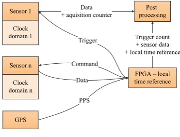
The low-level sensor fusion is realized by a FPGA board that has a different set of Add-ons attached. Depending on the appli-cation, major interface standards of low bandwidth sensors like SPI, CAN, RS232, digital in/outputs are supported. Dependent from the application, high data rate standards like CameraLink, Gigabit Ethernet, PCIExpress, and USB are also employed. The FPGA device type ranges from low power, low cost devices to more powerful FPGAs that are used for image processing.
FPGA – local + local time reference Trigger
Figure 3: Low level sensor fusion.
local time scale that is kept by the FPGA. A high precision clock generates timestamps to which all sensor communication is ref-erenced. Figure 3 shows an overview how the data and triggers information is passed to the processing host. Common practice to align external measurements that are not captured by our cus-tom hardware may either be a synchronized external trigger to the sensor or a known reference to the GPS time signal.
3 SOFTWARE CONCEPT
The main objective for the data handling software is to set up a data processing chain from low level data to high level informa-tion (e.g. from sensor measurements to a navigainforma-tion soluinforma-tion). Ideally, a particular task is encapsulated in a container, having only defined inputs and outputs. If input data is available, the task is immediately executed and send to a output buffer. It is important to have buffer capabilities as a succeeding task may not be ready to receive new data at the moment when it is gener-ated. Combining those containers, calledfeederin the following, allows for a flexible, efficient data handling, and data processing.
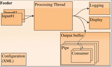
3.1 Feeder
A Feeder is designed to provide a base structure for data exchange and data processing but also facilitates the saving and display of data. As already stated, synchronized data is a prerequisite for further data processing. Therefore we definefeeder dataas a structure containing a time stamp and an arbitrary data type. For example by using Runtime Type Information (C++) any type of data can be exchanged. This could be a set of measurements (e.g. an array of double values) or an image. Each feeder has an out-put buffer, which is divided in differentpipes, to pass data to consecutive feeders. For any of these succeeding feeders con-sumerobject are instantiated. Via these consumers, the data from the output pipes of the preceding feeder can be read. Multiple consumers for a pipe are allowed. A consumer is a FIFO buffer holding a set of feeder data.
Feeder
Figure 4: Feeder structure
Figure 5 shows two different types of feeder: middleware-feeder and application-feeder.
Middleware-feeder The data grabbing is done by middelware-feeders, responsible for the communication to a hardware (e.g. FPGA, camera or hard disc). In case of theFPGA-feeder, com-munication channels are set up to control the connected sensor and to receive sensor data. The particular feeder knows the sen-sor protocol, allocates memory and fills the feeder data structure. It also saves the received data as a binary file. In offline mode this file can be loaded again using afile-feeder. Another exam-ple for a middleware-feeder is thecamera-feederwhich controls
the camera configuration and grabs images from the camera. A hardware trigger generated from the FPGA and controlled by a FPGA-feeder is used for the synchronization of the camera im-ages to the FPGA time base.
Application-feeder Application feeder are used for further pro-cessing of the data. The implementation of algorithms is highly simplified as the feeder structure provides the basic structures and it is already taken care of data grabbing and synchronization is-sues. For instance the ego motion calculation, including stereo image tracking and fusing the sensor data, is realized within a feeder. Its output (local position and orientation) is again used for consecutive processing steps. When switching from online mode to offline mode only the middelware-feeders are affected as they are replaced by their file feeder counterparts.
Hardware –
Sensors
Hardware –
Grabbing
Middleware –
Feeder Application – Feeder Trigger
Figure 5: Example for sensor data processing chain
4 CALIBRATION AND SENSOR REGISTRATION
Another, often underestimated problem is the complex alignment procedure for the complete sensor system. Only the knowledge of rotational and translational connections between the different sensors makes it possible to assign their measurements to the cor-responding frame of reference. One basic requirement for consis-tent calibration and sensor registration is synchronicity of all sen-sor outputs. This condition is realized through the internal clock generator of the FPGA board, which provides every incoming data with an uniquely defined time stamp. Furthermore the kind of physical sensor quantities have to be considered. The IMU measures raw (noise-corrupted) accelerations and angular veloci-ties while cameras emit images. These parameters are not directly comparable, so it is necessary to find an appropriate physical base for calculations.
First step is to calibrate the stereo camera system as shown in sec-tion 4.1. It is now feasible to calculate the rotasec-tion between era and IMU respectively tilt sensor. The orientation of the cam-era system, the IMU and the tilt angles are measured with a few static positions in front of a calibration chart. Determining the translation between camera system and IMU is more ambitious. With static positions IMU errors (e.g. offsets, scale factors) are inseparable from translational parameters. Thus a dynamic regis-tration procedure is needed, whereby the translation of the system has to be estimated with a Kalman filter. An absolute reference for the dynamic registration move would make it much easier to obtain the alignment parameters.
4.1 Camera calibration
1971). In case of a stereo vision system this is extended by the exterior orientation between the cameras. Several methods for calibrating camera systems have been proposed. Many of them use observations of predefined calibration grids to extract all cam-era parameters with a complex bundle adjustment (Zhang, 2000, Tsai, 1987).
Another way, eliminating problems with the classic approaches is to use holographic pattern to achieve a reliable camera cal-ibration (Grießbach et al., 2008). This methode uses custom-made diffractive optical elements working as beam splitters with precisely known diffraction angles. The virtual sources of the diffracted beams are points at infinity, which gives an image in-variant against translation. This particular feature allows a com-plete camera calibration with a single image avoiding complex bundle adjustments, resulting in a very fast, easy to use and reli-able calibration procedure. The method was shown on an wide-angle lens but also applies for far field calibration with telephoto lenses which is difficult to do with classical methods.
4.2 Sensor registration
The rotation determination between camera and IMU with a static registration procedure requires the use of the accelerometer mea-surements. Thus avoids the risk of working with erroneous in-tegrated sensor values because of summed offsets. At the same time it is possible to eliminate the effect of IMU offsets, adding them to the estimation model.
The measuring configuration consists of the multi-sensor system mounted on a tripod in front of a calibration chart. Figure 6 shows the rotatory connections of the setup. Solid arrows represent mea-sured values, dashed arrows unknown quantities. For registration the whole system is set to various positions so that the cameras always capture the calibration chart, i.e. the camera measure-ments refer to the calibration chart framework while IMU or tilt outputs relate to the local level with a loose z-axis rotation. The
Camera
local level with loose z-axis rotation
Figure 6: IPS rotatory connections
left subscriptzyxof the direction cosine matrixR(Titterton and Weston, 2004) denotes the three freedom degrees, the right part ofRindicates a rotation from the camera system (C) to the cali-bration chart (CC).zyxRCCC is simply obtained using the "DLR Calibration Detection Toolbox", developed at the DLR Institute of Robotics and Mechatronics (Sepp and Fuchs, 2005).
zyxRCCC =
yxRtCCCC
T
·zRtCCtI ·yxRtII ·zyxRIC (1)
The first term on the right-hand side of equation 1 denotes a two-axis rotation from the calibration chart to its tangential frame. The second term describes a z-axis rotation between the local
level IMU and calibration chart frame for every single position. The third matrixyxRtII =f azyx, abiaszyx
is a function of raw ac-celerometer outputs and their specific biases in three axes. This matrix includes measurements and unknowns at one time. The last term on the rightzyxRIC, the rotation from the camera to the IMU frame, contains the actual unknown physical values in terms of Euler angles.
The different position measurements and the relations of equa-tion 1 form an over-determined system of non-linear equaequa-tions with2 +i+ 3 + 3unknowns (i: number of positions). Minimiza-tion of the systems mean squared error can accomplished with an iterative algorithm like Gauss-Newton (Crassidis and Junkins, 2004). The three translational degrees of freedom between the camera and IMU are gauged manually. An inaccurate knowledge of the single sensors point of origin can turn out a problem. As indicated in figure 6, the camera-tilt registration strategy is equal to the currently described by replacing the IMU through the tilt sensor. Since the tilt sensor measures only angles the distance to the camera or IMU is not relevant. Following this, the last missing rotation among IMU and tilt can be calculated straight from previous results.
5 EXPERIMENTAL RESULTS
For visually aided inertial navigation different demonstrators for indoor environments and outdoor environments have been devel-oped. The core components are low cost inertial measurement units, inclinometers, both based on the MEMS technology and stereo camera setups. Compared to high quality IMUs that take advantage of sophisticated mechanical, fibre optic or ring laser gyroscopes, the MEMS-based IMUs are inferior regarding noise and bias stability. On the other hand they are much cheaper, more robust and reasonably smaller (Schmidt, 2009). The used IMU shows noise terms of 0.035 deg/s and a bias stability of 6.2 deg/hr for the gyroscopes respectively 4.1 / 0.17 mg for the acceleration sensors. The data rate is 450 Hz.
In the current setup the INS is aided by a stereo camera system that provides increments of attitude and position. Depending on the application requirements, the stereo camera settings are ad-justed accordingly (see table 1).
Frequency max. 30 Hz Sensor size 1360×1024 Pixel size 6.45µm
Indoor Setup
Focal length 4.8 mm Field of view 42.8×34.5 deg
Baseline 200 mm
Outdoor Setup
Focal length 12 mm Field of view 20.7×15.4 deg Baseline 500 mm
Table 1: Stereo camera setup
Figure 7: Sensor head with cameras, IMU and tilt sensor
5.1 Real time navigation
To show the capability of the system an indoor environment was chosen providing triangulated markers which were not used for navigation but only for validating the later result. The distance from a start mark to a second arbitrarily mark seen by the cam-eras had to be measured in real time without post processing the data. A course off about 90 m length leading over two floors was selected. At the beginning of every run the system was not moved for about 45 seconds to initialize the Kalman filter. This corre-sponds to 360 stereo images taken with 8 Hz frame rate. Due to a bottleneck within image processing this is the maximum rate the system can cope with. After this time the filter has "run in" and walking the course could be started.
With normal walking speed of about 1.5 m/s the destination mark was reached after 85-90 seconds with a final distance error of 20-50 cm for several runs. This difference is mainly caused by phases where no or little features could be seen resulting in no or low quality vision data and as a consequence an increased er-ror grow from integrating the IMU measurements. This situation occurs through difficult and changing lighting conditions, a low texturing at some areas or for example at narrow stairways with all objects to close for the stereo system. In good conditions the tracker uses up to 100 features and achieves a frame to frame position error of 5 mm respectively 2 mm for the viewing axis and an attitude error of about 0.2 / 0.1 degrees for typical indoor applications. This strongly depends on the number and distribu-tion of the seen features. Figure 8 shows the floor plan with the overlaid trajectory calculated from the system.
s x [m]
sy
[
m
]
-10 0 10 20 30 40 50 -10
0 10 20 30
Figure 8: Trajectory top view
5.2 3D Modeling
In a parallel processing chain the stereo image data is also used for dense stereo matching resulting in a disparity map. This map is converted into a depth map or a 3D environment model. To find
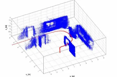
conjugate pixels, the matching algorithm implemented is Semi-Global Matching (SGM) (Hirschmüller, 2005), a very powerful but time consuming method. In order to fulfill the real time re-quirements the algorithm was implemented on a Graphical Pro-cessing Unit (Ernst and Hirschmüller, 2008). In combination with the navigation solution a high density point cloud was generated. Figure 9 shows a part of the 3D point cloud and the IPS trajectory at the start of the measurement run. Floor and ceiling points are hidden. A side view of the first and second floor including the staircase can be seen in figure 10. Again the building is sliced for better visibility. Both figures are generated with a reduced point set showing less than 1% of the data.
Figure 9: Combined IPS trajectory (doted red) and 3D point cloud (blue)
Figure 10: Side view of 3D point cloud
6 CONCLUSION
REFERENCES
Brown, D. C., 1971. Close-range camera calibration. Photogram-metric Engineering 37, pp. 855–866.
Crassidis, J. L. and Junkins, J. L., 2004. Optimal Estimation of Dynamic Systems. Chapman and Hall/CRC.
Ernst, I. and Hirschmüller, H., 2008. Mutual information based semi-global stereo matching on the gpu. In: ISVC ’08: Proceed-ings of the 4th International Symposium on Advances in Visual Computing, Springer-Verlag, pp. 228–239.
Grießbach, D., Bauer, M., Hermerschmidt, A., Krüger, S., Scheele, M. and Schischmanow, A., 2008. Geometrical camera calibration with diffractive optical elements. Opt. Express 16(25), pp. 20241–20248.
Hirschmüller, H., 2005. Accurate and efficient stereo processing by semi-global matching and mutual information. In: CVPR ’05: Proceedings of the 2005 IEEE Computer Society Conference on Computer Vision and Pattern Recognition (CVPR’05) - Volume 2, IEEE Computer Society, pp. 807–814.
Schmidt, G. T., 2009. Ins/gps technology trends. In: RTO-EN-SET-116, Low-Cost Navigation Sensors and Integration Technol-ogy.
Sepp, W. and Fuchs, S., 2005. DLR Calibration Detection Tool-box (DLR CalDe). DLR Institute of Robotics and Mechatronics, Oberpfaffenhofen/ Germany. http://www.robotic.dlr.de/callab (April 2012).
Titterton, D. H. and Weston, J. L., 2004. Strapdown Inertial Nav-igation Technology. MIT Lincoln Laboratory.
Tsai, R., 1987. A versatile camera calibration technique for high-accuracy 3d machine vision metrology using off-the-shelf tv cam-eras and lenses. Robotics and Automation, IEEE Journal of 3(4), pp. 323–344.
Zeimpekis, V., Giaglis, G. M. and Lekakos, G., 2003. A tax-onomy of indoor and outdoor positioning techniques for mobile location services. SIGecom Exch. 3(4), pp. 19–27.