TOWARD REAL TIME UAVS
’
IMAGE MOSAICKING
S. Mehrdad a*, M. satari a, M. Safdary b, P. Moallem c
a Dept. of Geomatic Engineering ,University of Isfahan, Isfahan, Iran – (s.mehrdad, sattari)@eng.ui.ac.ir b Dept. of electrical Engineering ,University of Isfahan, Isfahan, Iran – [email protected] c Dept. of electrical Engineering ,University of Isfahan, Isfahan, Iran – [email protected]
KEY WORDS: Fast mosaicking, UAVs’ image sequence matching, Fast local descriptor based matching, Epipolar geometry
ABSTRACT:
Anyone knows that sudden catastrophes can instantly do great damage. Fast and accurate acquisition of catastrophe information is an essential task for minimize life and property damage. Compared with other ways of catastrophe data acquisition, UAV based platforms can optimize time, cost and accuracy of the data acquisition, as a result UAVs’ data has become the first choice in such condition. In this paper, a novel and fast strategy is proposed for registering and mosaicking of UAVs’ image data. Firstly, imprecise image positions are used to find adjoining frames. Then matching process is done by a novel matching method. With keeping Sift in mind, this fast matching method is introduced, which uses images exposure time geometry, SIFT point detector and rBRIEF descriptor vector in order to match points efficiency, and by efficiency we mean not only time efficiency but also elimination of mismatch points. This method uses each image sequence imprecise attitude in order to use Epipolar geometry to both restricting search space of matching and eliminating mismatch points. In consideration of reaching to images imprecise attitude and positions we calibrated the UAV’s sensors. After matching process, RANSAC is used to eliminate mismatched tie points. In order to obtain final mosaic, image histograms are equalized and a weighted average method is used to image composition in overlapping areas. The total RMSE over all matching points is 1.72 m.
1. INTRODUCTION
Compare with other traditional ways of gathering comprehensive information of catastrophes, which is crucial for catastrophes relief and rescue, Unmanned Aerial Vehicle (UAV) based platforms photogrammetry has many advantages. In particular they are more flexible, which means they can be used in different weather conditions and with several operations. Moreover, high resolution image and precise position data can be acquired with lower cost using UAVs. According to these advantages, UAVs have become the first choice to gather this information. Low accuracy Global Positioning System (GPS), Inertial Measurement Unit (IMU) sensors and small frame high resolution camera are used in UAV based platforms due to their cost and weight limitation. The views of UAV images are often smaller than catastrophe field, so these images should be pasted together in order to increase the visual field. Therefore, mosaicking UAV images is a critical task.
Image mosaicking is the process of joining overlapping images together to form a larger image (Botterill et al, 2010). This is widespread and frequently referred to in literature. The review papers by Szeliski (2006), Zitova´ and Flusser (2003) describe this literature in details. Zitova´ and Flusser (2003) identify four stages that most image mosaicking and registration processes have in common (Botterill et al, 2010). These are:
1. Feature detection: Salient elements of each image are identified and located.
2. Feature matching: Correspondence between features are established, typically by comparing feature descriptors. 3. Transform estimation: The correspondence between features is used to determine a transform that maps one image to the other.
* Corresponding author S. Mehrdad, [email protected]
4. Image composition: The images are transformed and aligned with one another. Some form of interpolation is often applied to blend the images.
Both quickness and elimination of moving points should be considered in catastrophe images mosaicking algorithms. Automatic mosaicking is needed a point matching method to extract tie points. Local Descriptor Based Matching (LDBM) methods are greatly in use nowadays. These methods have two general steps, including keypoints detector and point descriptor which satisfy firs two steps of mosaicking process mentioned above. UAV images have different attitude parameters in compare with each other due to instability of UAV platforms during their flight. Therefore we should use a LDBM method for these image sequences that is robust against geometric image transformations such as rotation and scale. Scale Invariant Feature Transform (SIFT) that was introduced by David G. Lowe is a LDBM method that is invariant to uniform scaling, orientation and partially invariant to affine distortion and illumination changes (Lowe, 1999). SIFT point descriptor has drawbacks in terms of computation cost and memory usage (Botterill et al, 2010). These drawbacks prevent using this method for running on devices equipped with a low-end CPU such as mobile PC and UAV processors.
In this paper a novel and fast strategy is proposed for registration and mosaicking UAV images. Firstly, imaging sensors and low cost GPS/IMU were calibrated and Imprecise Exterior Orientation Parameters (IEOP) of each image are measured. In the next step, SIFT point detector which uses heretical pyramid structure is used to extract feature points from images. In order to extract description vector Rotation-Aware Binary Robust Independent Elementary Feature (rBRIEF) which is fast and robust against scale and rotation variety is used (Rublee et al, 2011). Imprecise image positions are used to find out images that
contain same scene – i.e. set of previous images that matches to the new image are introduced. In continue of the process, k-nearest-neighbor method is used for matching description vector of feature points. In order to improve computation time, the k-nearest method performed in Epipolar Rectangle (ER) related to each feature point. ERs are built based on Epipolar line offsets by considering accuracies of IEOPs. Then Random Sample Consensus (RANSAC) is used to eliminating mismatching tie points. The use of ERs and RANSAC helps to eliminate moving points from matching process and lets us achieve robust points’ network. All the sequence images are added to the bundle adjuster one by one, and the parameters can be updated by using the L-M (Levenberg-Marquardt) algorithm (Press et al, 1992). In order to obtain final mosaic, image histograms are equalized and a weighted average method is used to image composition in overlapping areas.
Despite many successful applications on image mosaicking, there are still some restrictions in automatic mosaicking which have a lasting impact on the output time and quality. The most important one is that well-doing the four different steps of mosaicking are time-consuming, that is the more time each step consume, the more quality it performs, so that it is much troublesome to balance time efficiency and quality over each step. This algorithm tries to overcome some of these restrictions, for instance it tries to minimize the time of matching process. We will detail each role in the following subsections.
2. METHODOLOGY
2.1 Sensors calibration process
In order to get every image imprecise attitude and position parameters, we need to calibrate the UAV’s sensors individually and relative to each other – i.e. determine lever arm offsets and boresight mis-alignments between the UAV’s sensors, and lens distortion parameters. For this reason, a 300*700 m test field gridded at 50*50 m control points with circular pattern targets (figure 1) is used for self-calibration bundle adjustment based on El-scheimy model (El-sheimy, 2000).
2.2 Find adjoining frames
The distance from the camera to the target objects is very much greater than the motion of the camera between views and image planes have less tilt, so the adjoining images can be obtained with imprecise position and heading attitude parameters. At this point, frame size and geometric parameters of flight and camera, and positioning system precision should be considered to set thresholds which images within this thresholds known as the adjoining frames of the new image. We use heading parameter to know if we have heading overlap or side overlap and set different threshold for each one. To find all available images in the vicinity of the latest frame we use these thresholds and compare this frame position and heading with earlier images parameters. This causes time efficiency and we will use it in final adjustment.
2.3 Feature detection
The SIFT algorithm was proposed by David G. Lowe in 1999 to detect and describe feature points which are invariant to images scaling, translation, and rotation, and partially invariant to illumination changes and affine or 3D projection (Lowe, 1999). SIFT feature extraction is generally classified into four steps: Detect extreme value in scale space, tie point positioning, dominant orientation assignment, and descriptor generation (Li et al, 2012). Specifically, in order to achieve rotation invariance
(a)
(b)
(c)
Figure 1. Calibration test field specifications. (a) Highlights test field (yellow rectangular) and an image frame of test field for instance (red rectangular). (b) Shows an
image that highlighted in (a). (c) Specifies a control point in image frame highlighting by green rectangular in (b)
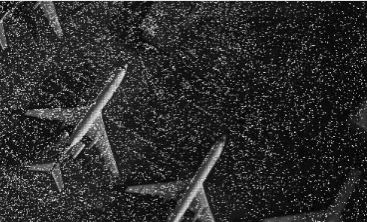
and a high level of efficiency, SIFT point detector selects key locations at maxima and minima of a difference of Gaussian function applied in scale space. This can be computed very efficiently by building an image pyramid with resampling between each level. Furthermore, it locates key points at regions and scales of high variation, making these locations particularly stable for characterizing the image (Lowe, 1999). SIFT point detector which described above is used to detect and localize feature point in this paper (figure 2). In order to achieve points
Figure 2. Feature points extracted from an image
distribution efficacy we divide each image frame to a 5*6 girded subspace, and then choose 10 points randomly in each subspace if there were enough points. This will lead to maximum number of 300 points in each image. We only use these points in subsequent steps. This will lead to both time and computational efficiency.
2.4 Feature matching
First of all we need a point descriptor to describe the area around each feature point that is specified in last stage. Like we said before, this descriptor should be robust against geometric image transformations such as rotation and scale. We use rBRIEF descriptor as our point descriptor in our algorithm. After that each feature point in the image need to be find and match in every adjoining images set of this image that contain this point. For this reason, for every feature point corresponding ERs are performing in every image of adjoining images set. Then k-nearest method is used to find any corresponding point between every point in the image and the points in its ERs if this point exist in any of ERs. This will limit search area for every point in the image with geometric restriction. This has two advantage, the first one is to speed up the matching process and the second one is to increase the chance of elimination of moving points. The detail of using of ERs and rBRIEF is represented in the following.
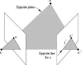
2.4.1 Epipolar rectangle (RE): We consider two perspective images of a scene and a point X in the scene, let and ′ be its mapping in two images through the camera centres and ′ (figure 3)
Figure 3. Epipolar plane and Epipolar line
The point X, the camera centres and ′, the mapped points and ′ will lie in the same plane named Epipolar plane. In other words given a point in the first image, the Epipolar plane is defined by the ray through and and the baseline through and ′. A corresponding point thus has to lie on the intersecting line ′ between Epipolar plane and the second image plane. The line ′ is projection of the ray through and X in the second image and is called the Epipolar line for . The Epipolar line corresponded to every feature point in an image can be performed in every image in its adjoining images set, if relative attitude and position between images is well known. Since we only have imprecise attitude and position parameters this line is converted to a rectangle (figure 4). The specification of this rectangle is determined by a covariance matrix which is performed using attitude and position precision and Epipolar geometry equations (Ishikawa, 2006).
2.4.2 rBRIEF feature descriptor: BRIEF ( Binary Robust Independent Elementary Feature) is an algorithm that uses binary strings as an efficient feature point descriptor. BRIEF is not designed to be rotationally invariant (Rublee et al, 2011).
(a)
(b)
Figure 4. Image sequence Epipolar rectangle. First image of sequence with a specified point on it (a) with its Epipolar
Rectangular in second image (b).
Rotation-Aware BRIEF (rBRIEF) is an extension of BRIEF method that makes BRIEF description vector robust against rotation by use of image intensity centroid (Rublee et al, 2011). The BRIEF descriptor is a bit string description of an image patch constructed from a set of binary intensity tests. Consider a smoothed image patch, p a binary test � is defined by:
� p: , = { ,, : p: p < q≥ q (1)
where p is the intensity of pat a point . The feature is defined as a vector of n binary tests:
� = ∑ −
≤ ≤�
� p: , (2)
So this defines an array of n descriptor for every point. The more the n gets, the better it describes point surrounding and the more time it spends. In order to balance the time efficiency and descriptor quality we set n equal to 128. In order to making this descriptor robust against rotation a more efficient method is to steer BRIEF according to the orientation of keypoints (Rublee et al, 2011). For any feature set of n binary tests at location , , define the ∗ matrix:
� = [ , … ,, … , ��] (3)
Using the patch orientation θ which is calculated from intensity centroid algorithm (Rublee et al, 2011), we construct �θ that is the steered version of S. then the new steered BRIEF operator which is named rBRIEF, becomes:
� p, θ = � p | , ∈ �θ (4) Rotation and scaling robustness of this method and SIFT method is compared and showed in figure 5 and 6.
Figure 5. Comparison between SIFT and rBRIEF and BRIEF descriptors in rotation
(a)
(b)
Figure 6. Comparison between Sift and rBRIEF descriptors in rotation (a) and scale (b)
2.5 Transform estimation
The next step is to compute the geometric relationship between neighbourhood images. The relationship between two images can be considered as perspective projection:
{
′= + +
+ +
′= + +
+ +
(5)
Where , are first image coordinates and ′, ′ are second image coordinates. The 8 parameters of this transform can be represented as a 3*3 matrix denoted by:
� = [ ] (6)
Given at least four points correspondence we can estimate perspective transform. We use RANSAC approach to solve this transform. RANSAC works by repeatedly selecting small random subsets of correspondences (hypothesis sets) from which to compute candidate solutions. Each candidate solution is compared with the entire data set until a solution compatible with a large number of correspondences is found. These are assumed to be inliers, and a least-squares solution is computed from this inlier set and other points are eliminated from the process (Botterill et al, 2010). This can eliminate remained mismatch
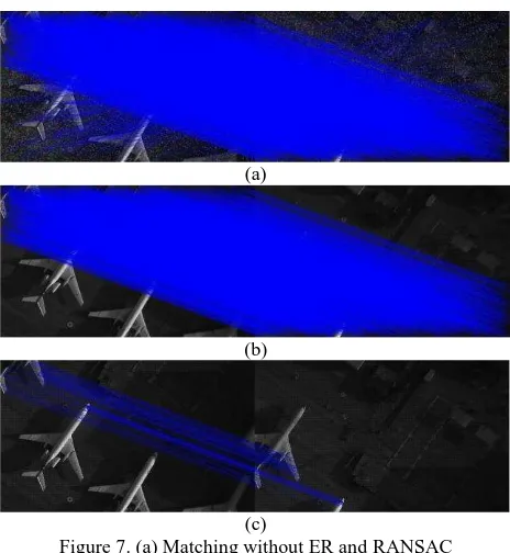
points. Figure 7 shows some examples of matching points with processing ER and RANSAC and without them.
(a)
(b)
(c)
Figure 7. (a) Matching without ER and RANSAC (b) Matching with ER and RANSAC (c) Some example of matching points.
2.6 Transform optimization
However the two images will rarely line up exactly, due to a combination of small errors remaining in the transform estimate, uncorrected lens distortion, and intensity variation between images. In the case of aerial images the fact that the ground is not exactly planar adds to this misalignment (Botterill et al, 2010). In order to minimize these accumulation errors we need to optimize our transformations. We need to use bundle adjustment to improve all the transformation globally. This step can solve the problems caused by the accumulated errors. All the sequence images are added to the bundle adjuster one by one, and the parameters can be updated by using the L-M (Levenberg-Marquardt) algorithm (Press et al, 1992).
The objective function we use is a sum squared projection error. Each feature point is projected into every image in which it matches, and the sum of squared distances is minimized. The squared residual can be computed by:
� = � ( � , �� ) + � ( � , �� ) (7)
Where �� is is the projection from image i to image j of the feature point corresponding to � and we can use the following equation to compute �� :
�� = � � (8)
Where � is the transform matrix between image and . It should be noted that the transform matrix between the firs image and the kth image can be expressed as:
� = ∏ � −
=
(9)
So using the equation 9 we can perform the relation between every images in the process. Then the error function is the sum over all the images of the squared residuals:
� = ∑ ∑ ∑ � estimation of transform parameters to operate the algorithm. This is a non-linear least squares problem which can be solved by using L-M algorithm with iterative process (Cheng et al, 2010).
2.7 Image composition
In order to make the final mosaic all the images need to transfer to a same frame, so the reference plane need to be specified. At this point we use IEOPs to reach attitude correction image of first image that is the image that does not have any tilt. We use this new plane as our reference frame and all images transform parameters estimate with this reference frame. Like we said before, our optimization algorithm needed first estimation of transform parameters and this would be provided by estimating the parameters obtained by RANSAC approach between each image and its prior image and use of equation 9 to achieve the parameters between every two images. After optimization process we need to use these optimized parameters to register each image to the reference plane. In this step there are many overlapping areas. Directly overlay images after registration will appear obvious seamline, adverse visual feelings and low-quality stitching. To overcome this, there are a lot of proposed methods. Each method has sort of advantages and disadvantages. Two common solutions to this problem are firstly to choose seams minimizing visual discontinuities, or secondly to hide seams by interpolating between overlapping images (Botterill et al, 2010). The first approach has a disadvantage of time-consuming and an advantage of good visual view. A variation of the first approach is used by Brown et al (2007), which successfully hides seams, although moving objects or poor alignment can result in multiple images of objects appearing named ghosting (Botterill et al, 2010). We use a similar approach that uses weighted averaging. This has the advantage of time efficiency. Moreover there are also many factors that affect the quality of image stitching, one of them is exposure differences. In order to minimize exposure differences between images we use histogram equalization before stitching process.
3. THE EXPEREMENT SYSTEM DESIGN AND RESULTS ANALYSIS
This paper introduces a UAVs mosaicking method which is collection of different approaches and ideas. It is designed to minimize computation time of process. It uses IEOPs of the UAV in order to minimize computation time as much as possible. After using SIFT point detector for extracting images salient elements, the rBRIEF descriptor which is time efficient and robust against geometric transformations is used to describe points. In the matching process the UAV’s IEOPs is used to extract Epipolar rectangle to minimize search area of detected points which reduces the time of process and uses as mismatch points eliminator. In the matching process, it matches maximum 100 points between each two overlapped images. It also chose points from different region of images in order to keep points
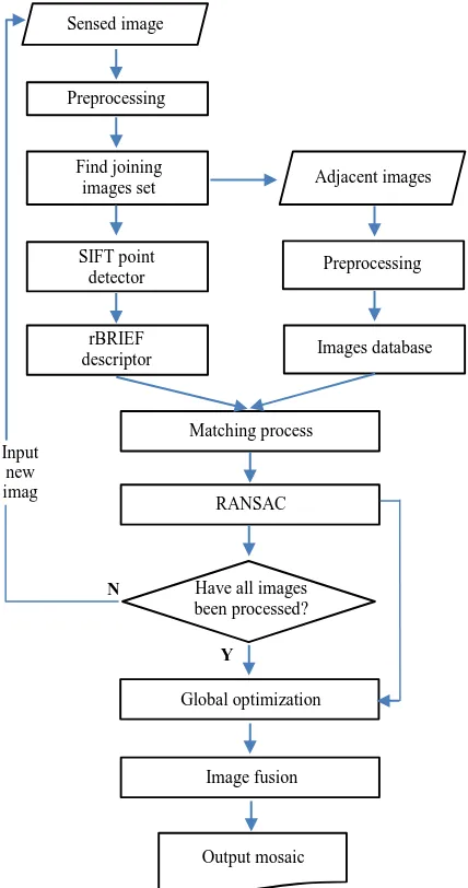
distribution efficient. The 8 projective transformation parameters then be calculated using RANSAC approach which eliminates remained mismatch tie points. A global bundle adjustment is used to minimize accumulation error in the process. The most time efficiency methods is used in image stitching process. C++ programing language is used to implement the algorithm process. We use multithreaded programing in order to maximize time efficiency. Figure 8 shows the flowchart of the algorithm.
The implement of this paper algorithm is performed on a desktop computer with a 3.20 GHz Intel core i7 processor and 8GB RAM. The size of images is 1500*2500 pixels and the images Ground Sample Size (GSD) is about 7 cm. The rate of heading and cross overlap are about 70% and 40% respectively. The average flight height of the UAV is about 1000 m. Table 1 shows the hardware specification that are used in this research.
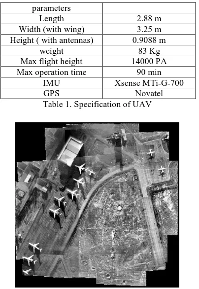
An experiment mosaic with 40 images has been performed using this method over our test field (figure 9). The total RMSE over all matching points is 1.72 m. Matching time and RMSE and other statistical data for an image with maximum joining image set (11 images) are shown in table 2. Mosaic time for each image
Sensed image
depend on its parameter optimization time and overlap area, varies in 1-3 s range.
parameters
Length 2.88 m
Width (with wing) 3.25 m Height ( with antennas) 0.9088 m
weight 83 Kg
Max flight height 14000 PA Max operation time 90 min
IMU Xsense MTi-G-700
GPS Novatel
Table 1. Specification of UAV
Figure 9. The mosaic over test field
Images ID Match points number
Total RMSE (m)
Match time
24-16 45 1.854
0.9135 s
24-17 67 1.783
24-18 19 1.913
24-22 65 1.633
24-23 93 1.586
24-25 95 1.564
24-26 74 1.594
24-27 31 1.756
24-30 22 1.932
24-31 59 1.901
24-32 48 1.887
Table 2. Specification of UAV
4. CONCLUSIONS
Investigation of experimental result shows that the proposed algorithm which uses maximum geometric and computational potentials to minimize mosaicking time, presents a system for fully automatic panorama mosaicking and high efficient on registration and mosaicking process with time consideration. But there are still some problems include fusion ghost which can be minimized using methods that find optimum seam paths. And of course using of GPU can significantly reduce the time of process. UAVs automatic mosaicking can provide short-time information that can minimize life and property damage.
REFERENCES
Botterill, T. Mills, S. Green, R., 2010. Real-time aerial image mosaicking. In: Image and Vision Computing New Zealand (IVCNZ), 2010 25th, IEEE, pp. 1-8
Brown, M. Lowe, D. G., 2007. Automatic panoramic image stitching using invariant features. International journal of computer vision, 74(1), pp. 59-73.
Cheng, X. Wang, J. Xu, Y., 2010. A method for building a mosaic with UAV images. International Journal of Information Engineering and Electronic Business, 2(1), pp. 9-15.
El-sheimy, N., 2000. Inertial Techniques and IMU/DGPS integration, Department of Geomatics Engineering, The University of Calgary.
Ishikawa, H. Geiger, D., 1998. Occlusions, discontinuities, and epipolar lines in stereo. InComputer Vision—ECCV'98, pp. 232-248. Springer Berlin Heidelberg.
Li, M. Li, D. Fan, D., 2012. A Study On Automatic UAV Image Mosaic Method For Paroxysmal Disaster. In:Proceedings of the International Society of Photogrammetry and Remote Sensing Congress, Melbourne, Australia, Vol. 25, pp. 123-128
Lowe, D. G., 1999. Object recognition from local scale-invariant features. In: Computer vision, 1999. The proceedings of the seventh IEEE international conference on, Vol. 2, pp. 1150-1157). IEEE.
Press, W. Teukolsky, S. Vetterling, W. Flannery, B., 1992.Numerical Recipes in C: The Art of Scientific Computing. Cambridge University Press.
Rublee, E. Rabaud, V. Konolige, K. Bradski, G., 2011. ORB: an efficient alternative to SIFT or SURF. In: Computer Vision (ICCV), 2011 IEEE International Conference on, pp. 2564-2571). IEEE.
Szeliski, R., 2006. Image alignment and stitching: A tutorial. Foundations and Trends® in Computer Graphics and Vision2, no. 1, pp. 1-104.
Zitova´, B. Flusser, J., (2003). Image registration methods: a survey. Image and vision computing,21(11), pp. 977-1000