4D ANIMATION RECONSTRUCTION FROM MULTI-CAMERA COORDINATES
TRANSFORMATION
J.P. Jhan a*, J.Y. Rau a, C.M. Chou b
a Department of Geomatics, National Cheng Kung University, Tainan, Taiwan - ([email protected], [email protected])
b Kuo Toong International CO., LTD., Taiwan- ([email protected])
Commission V, WG V/5
KEY WORDS: Close-Range Photogrammetry, Conformal Transformation, 4D Animation
ABSTRACT:
Reservoir dredging issues are important to extend the life of reservoir. The most effective and cost reduction way is to construct a tunnel to desilt the bottom sediment. Conventional technique is to construct a cofferdam to separate the water, construct the intake of tunnel inside and remove the cofferdam afterwards. In Taiwan, the ZengWen reservoir dredging project will install an Elephant-trunk Steel Pipe (ETSP) in the water to connect the desilting tunnel without building the cofferdam. Since the installation is critical to the whole project, a 1:20 model was built to simulate the installation steps in a towing tank, i.e. launching, dragging, water injection, and sinking. To increase the construction safety, photogrammetry technic is adopted to record images during the simulation, compute its transformation parameters for dynamic analysis and reconstruct the 4D animations. In this study, several Australis© coded targets are fixed on the surface of ETSP for auto-recognition and measurement. The cameras orientations are computed by space resection where the 3D coordinates of coded targets are measured. Two approaches for motion parameters computation are proposed, i.e. performing 3D conformal transformation from the coordinates of cameras and relative orientation computation by the orientation of single camera. Experimental results show the 3D conformal transformation can achieve sub-mm simulation results, and relative orientation computation shows the flexibility for dynamic motion analysis which is easier and more efficiency.
1. INTRODUCTION
Reservoir dredging is a critical issue for extending the life of reservoir. Generally, it can be achieved by three ways, i.e. operating a grab dredger on the water surface to dig the bottom silt of reservoir, digging silt on the shore during the dry season, or construct a desilting tunnel for dredging. The desilting tunnel is the most effective and cost reduction way among them, in which the others need further costs to transport the silt down the mountain.
In Taiwan, reservoirs are the major water source for agriculture, industrial and livelihood purposes. The capacity of reservoirs will be filled during the typhoon season. However, typhoons bring not only fresh water but also heavy rains that may cause landslide on mountainous area. It will cause seriously siltation problem of reservoirs by the deposition of soil, rocks, and woods that are flushed down from the upper stream. The ZengWen reservoir, the biggest one in Taiwan, has capacity of 6 billion m3. In average, its siltation rate is 4 million m3 per year since 1973 when it was built and before the attack by typhoon Morakot. The typhoon Morakot (Li et al., 2013) cause many landslides in mountainous area, serious flood on the plain, and brought 90 million m3 silt that caused dramatically damage to the water inlet of tunnel and generator.
In order to increase the ability of desilting and extend the life of ZengWen reservoir, a new dredging project by constructing a new
* Corresponding author
desilting tunnel is proposed. Conventional construction method needs to build a cofferdam in advance to separate the water, then construct the intake of tunnel inside and demolish the cofferdam afterwards. Instead, the dredging project will install a huge steel pipe in the water without building a cofferdam. The huge steel pipe, also called Elephant Trunk Steel Pipe (ETSP), is design to connect the tunnel and the bottom of reservoir. The muddy water of the bottom will be drained out by the density current.
The size of ETSP is very huge, meaning transportation on the land is nearly impossible. Therefore, it will be assembled on the river shore, lunching to the water, dragging on the water to the installation site, and sinking to the bottom to connect the tunnel. Due to the installation of ETSP is the critical part of the whole project. In order to increase the construction safety and understand its motion phenomena during installation, several simulation procedures are needed. Thus, a 1:20 model of ETSP was built for simulating its installation procedures in a towing tank. To understand its motion phenomena, photogrammetry technic is adopted to record the images, compute the motion parameters, and reconstruction the 4D animation video for installation reference.
1.1. Elephant Trunk Steel Pipe (ETSP)
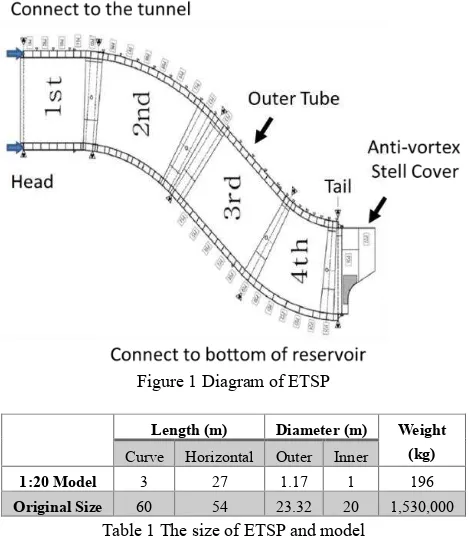
sinking. Its outer diameter and inner diameter is 23.32 and 20 meters, respectively. The distance of curve and horizontal is 60 and 54 meters respectively. The totall weight is 1.53 million kg. Figure 1 depicts its design, in which the head part is to connect the tunnel, and the tail with anti-vortex stell cover is to connect the bottom of the reservior. According to the design, about 76 % of the body will float on the surface when the nozzles are sealed with blind plates, which means dragging the ETSP on the water is possible.
For the installing simulation purposes, a 1:20 mdoel is built based on geometric similarity, meaning the scale ration of 3 dimensions are the same. Table 1 summzrizes both the sizes of model and original ETSP.
Original Size 60 54 23.32 20 1,530,000
Table 1 The size of ETSP and model
1.2. Installation Steps of ETSP
The installation of ETSP contains five different steps: (1) assembling the 28 rims at the shore of river, (2) lunching the ETSP into water, (3) dragging the ETSP from assembly site to the installation site, (4) injection water to the inner tube for orientation adjustment, (5) removed the blind plates in the water and (6) injection water into the compartments for sinking the ETSP to connect the desilting tunnel. Steps (2), (3), (4) and (6) are simulated to understand its motion phenomena during installation. Details are described in the following.
1.2.1. Lunching: The assembled ETSP will be placed by the riverside where the slope is about 8 degrees.When the raining season comes, the river level will rise and the buoyancy will push the ETSP up and float on the river. The simulation is to understand at which depth it will start to float, when will it totally float on the water, and does it turn during the floating.
1.2.2. Dragging: When the ETSP finally floating on the river, the
tugboats will drag the ETSP from the assembly site to the installation site. Since the dragging distance is about 8 km, the simulation is to understand will it forward straightly, and does it swing during the dragging.
1.2.3. Water Injection: The water injection is to inject water to the inner tube of ETSP. During this step, several buoys are tied at the head and the tail for adjusting the angle. It will sink slowly and rotate 90 degrees. This is the most important part since several divers will assist the installation in the water. To understand how will it rotate and How long when the rotation is ended is important to increase the safety.
1.2.4. Sinking: In this part, the inner tube of ETSP has full with water and rotated 90 degrees. When the two blind plates are removed in the water, the buoyancy still makes small part of head component floating on the water. By injecting water into the outer tube and turn on the valves for discharging air, the ETSP will sink and reach the bottom for installation.
1.3. Dynamic Monitoring by Photogrammetry
Photogrammetry technic can achieve sub-pixel accuracy for precise object measuring, structure monitoring (Maas and Hampel, 2006) and 3D model reconstruction (Rau and Yeh, 2012). In order to monitor the dynamic motion of a rigid object, several recognized artificial targets are needed to paste on the surface of object for measurement. The dynamic motion meaning the change of displacements and rotations, where can be computed by the comparison of the target’s 3D coordinates at different time sequences.
Generally, dynamic motion analysis can be conducted by performing forward intersection from multi-cameras in which the interior and exterior orientation parameters are calibrated. A higher overlap ratio among images and larger intersection angles are necessary to increase the intersection accuracy, and as many cameras as good to increase the computation redundancy. The motion parameters can be obtained by performing conformal transformation of conjugate 3D points at different time sequences. However, it is tedious to setup cameras since it has to make sure the overlap ratio and intersection angle among images, and the number of cameras will cause further costs as well.
2. EXPERIMENTAL SITE AND EQUIPMENT The experimental site for installation simulation and the equipment for recording are introduced here.
2.1. Experiment Site
The installation simulations of ETSP are experimented in a towing tank. Its size is length of 160 m, width of 8 m and depth of 4 m. There is a carriage above the towing tank as well that the speeds of carriage can be controlled by computer. It can be treated as a tugboat to simulate the long distance dragging. On the other hand, the lunching simulation is conducted in a small enclosed space (length of 7 m, width of 1.6 m, and depth of 1 m) and placed on a tilt steel frame with 8 degrees. It is located at the end of towing tank. In order to simulate the rising of river level, the water is injected to the space by pumps.
Figure 2 shows the installation situations of different cases. Due to the imaging conditions contain both static and dynamic motion, and monitoring in the air and underwater environments. Several devices including cameras, artificial target, tripods, housing, lighting source, synchronize trigger and time-lapse app are adopted.
Figure 2 Situations of installation simulation. (a) lunching, (b) dragging, (c) water injection and sinking, and (d) overview of
the towing tank.
2.2. Artificial Targets and Imaging Equipment
To reconstruct the 3D model of ETSP, the Australis codes (Fraser and Edmundson, 2000) are adopted and pasted on the surface of ETSP for auto-recognition and measurement. The coordinates of each target are computed for space resection in the camera orientation step. The codes are also used to build the camera calibration filed for both air and underwater environment.
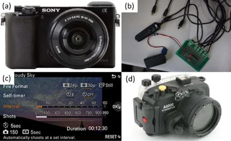
As shown in Figure 3, the adopted imaging equipment including camera, synchronize trigger, housing and time-lapse app. Three Sony 6000 cameras with 20 mm focal length are adopted for performing 3D conformal transformation. Its resolution is 24 million pixels with 4 um pixel size, meaning it can achieve 0.4 mm spatial resolution at 2 m away.
Figure 3 Imaging devices. (a) Sony A6000 with 20 mm focal length, (b) Synchronize trigger, (c) Time-lapse photography
app, and (d) Housings
Synchronized images acquisition is the major condition for dynamic motion monitoring. In this study, a synchronize trigger is developed and installing time-lapse apps in each camera. Therefore, once cameras are triggered, all cameras will continues take images at the same time in the same interval.
Considering the underwater photogrammetry for monitoring water injection and sinking, housings are used to protect camera. To acquire clearly images for codes detection, driers are putted inside the housing in case of fog caused by temperature difference. Figure 4 shows a sample images that image taken with drier can acquire clearly one. On the other hand, due to the imaging geometry of underwater is different to the air, the lens distortion calibration is critical for underwater photogrammetry.
Figure 4 Comparison of underwater images. (a) image taken without drier and (b) image taken with drier.
2.3. Other Devices
Tripods and lighting source are used to acquire clearly images. The tripods are used to fix the cameras positions during the monitoring. They are tied on the carriage and put into the water for the dragging and water injection cases, respectively. On the other hand, three energy saving blubs are adopted to increase the light of indoor environment, and for acquiring high contrast image for codes detection. Meanwhile, since the light is significantly absorbed by the water, a 25500 lumen waterproof LED is placed in the water to increase the light for underwater photogrammetry. Figure 2 also depicts the installation of light sources and tripods.
3. METHODOLOGY
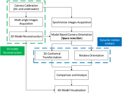
built for both cameras orientations and 4D animation reconstruction. For the dynamic motion analysis, the images are acquired synchronized and the orientations of cameras are computed by model based space resection, which means the coordinates of codes are measured. The motion parameters are obtained from both 3D conformal transformation and relative orientation computation. Differences are compared in this study. By combining the 3D model and the time interval of transformation parameters, the 4D animation can thus be generated.
Synchronize Images Acquisition
Model Based Camera Orientation (Space resection)
3D Conformal Transformation
4D Model Visualization
Relative Orientation
Comparison and Analysis 3D Model Reconstruction
Multi-angle Images Acquisition Camera Calibration (Air and underwater)
3D model Reconstruction
Dynamic motion analysis
Figure 5 Workflow for dynamic motion analysis and 4D animation reconstruction of ETSP
3.1. Camera Calibration
Camera calibration is to correct the lens distortion effect and increase the accuracy of measurement. In this study, both air and underwater environment are considered. The camera calibration in the air can be conducted by means of rotatable circle table calibration field (Rau and Yeh, 2012).
However, due to the refraction between different materiel, the calibration results in the air cannot be applied to the underwater environment. Therefore, as shows in Figure 7, an underwater calibration filed was built in the bottom of towing tank, where several Australis codes are fixed on the metal frame. The comparison of lens distortion curve among them are discussed in section 4.
Figure 6 Rotatable circle table camera calibration field (Rau and Yeh, 2012).
Figure 7 Underwater camera calibration filed.
3.2. 3D Model Reconstruction
In this study, the Australis© coded artificial targets and white dots are pasted on the surface for automatic recognition and measurement. The coordinates of each points are compute through bundle adjustment, where images are taken at different positions and viewing angles. The 3D model is then created in Autodesk 3ds Max© software by importing the 3D point for meshing and texturing. Figure 8 shows the distribution of Australis coded targets on the ETSP, the generated 3D model and its coordinate definition. The X axis is point to the head of ETSP, the Y axis locates on the horizontal plane and Z axis depicts the height direction. The original point is computed by the average value of all the coded targets, which is close to the weight center.
Figure 8 3D model of ETSP. (a) Distribution of Australis coded targets, (b) 3D model, and (c) the coordinate definition.
3.3. Dynamic Motion Analysis
The orientation parameters of each camera at different time sequence is computed by space resection. It is considered that the ETSP is fixed meaning cameras rotate and move with respect to the ETSP. Therefore, the transformations of cameras are representing the motions of ETSP. In this study, 3D conformal transformation from coordinates of three cameras at different time sequence, and relative orientation from single camera are performed and compared.
Figure 9 Camera orientation results of launching case.
3.3.1. 3D Conformal Transformation: The dynamic motion means the transformation among different times. It is represented by displacements ( , , ) and rotation angles (Ο, Ρ, Κ ). Considering ETSP is static and images are acquired in the same time, which means images in different time sequence has different coordinate system. The transformation parameters can thus be computed by performing 3D conformal transformation on the coordinates of cameras at different times.
The 3D conformal transformation is shown in equation (1). The ( , , ) is the position at original, and the ( i, i, i) meaning the positions after moving. The � ~� are the coefficients of rotation matrix.
[ ] = [ ] + [�� �� ��
� � � ] [
� � �
] (1)
3.3.2. Relative Orientation: The motion of camera is with respect to the ETSP, and since the position and angles are obtained by space resection, the transformation parameters can thus by computed by the relative orientation of single camera. The relative rotation angles are the motion angles that is computed from equation (2). In which � �� ��� denotes the
rotation matrix between different time series under the mapping frame of M, where � �� and � �� represent the ETSP at original and after moving, respectively. However, since only orientation angles of camera are computed, the �� ���� is
computed by �����×
��
�. On the other hand, the displacement was derived equation (3), in which � represents the position vector, ���� and ���� is the positon of camera at original and after
moving, respectively.
� ��
� ��=
�
� ��×
� ��
� (2)
�� �� ���=
� ��
� ��× �
���− ���� (3)
3.4. 4D Animation Reconstruction
The 4D animation is the dynamic motion of 3D model. It is generated by creating several time intervals, in which each one has a 3D model with different transformation parameters. Since images are obtained by time-lapse apps, the results are interpolated among time interval. As Figure 10 shows, the 4D animation can view at any position and any perspective angle, which is easier to understand its motion phenomena comprehensively than recording 2D video.
Figure 10 Split views of 4D animation
4. ANALYSIS AND DISCUSSIONS
The result of lens distortion comparison, the dynamic motion analysis of each case, and the comparison among two methods are discussed here.
4.1. Camera Calibration
Both air and underwater camera calibration are performed in this study. Due to the light are refracted when pathing through different materials, the imaging distance meaning the focal length are changed (Fraser and Al-Ajlouni, 2006). To analysis its difference, same camera with same focal length and focusing range is experiment.
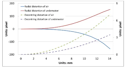
As Figure 7 shows, the radial lens distortion curve in the air and underwater environment are different. One shows barrel distortion effect and pincushion distortion effect is found in the other, in which the maximum value of distortion is about 150 pixels. Though the value of decentering distortion is low, the curve among them are different as well. Meanwhile, the calibrated focal length in air and underwater is 20.88 mm and 27.90 mm, respectively. The ratio is about 1.336 which similar to the water refraction index of 1.333.
Figure 11 Comparison of lens distortion curve among underwater and in the air.
4.2. Results of Dynamic Motion Analysis
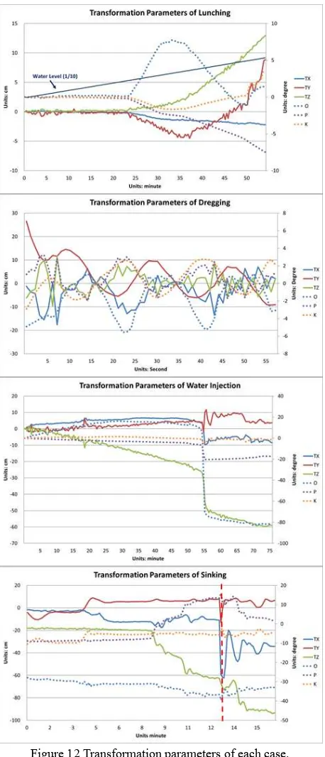
Figure 12 Transformation parameters of each case.
Cases Number of Images
Accuracy of 3D conformal transformation (mm)
Max Average
Lunching 164×3 0.48 0.11
Dragging 58×3 0.92 0.43
Water injection 181×3 2.00 0.08
Sinking 242×3 2.66 0.60
Table 2 Summarized accuracy of each case.
4.2.1. Lunching: In this case, the ETSP stay steady in the first 25 minutes, then it starts rising when water level reach to 50 centimeters. It finally floating on the water at 55 minutes when
the water level is about 1 meter. From the figure, the swing rotation effect is observed along X axis. It rotated clockwise about 10 degrees when start raising then counterclockwise to steady when it floating on the water. The y axis reaches to the horizontal plane at about rotating 8 degrees that corresponds to the slope of steel frame. Besides the raising of Z axis, only a few sentiments displacements are observed.
4.2.2. Dragging: The dragging speed is 1 m/s, and the dragging distance is 60 m. Since the X axis and the dragging direction are not parallel in the beginning, the ETSP move irregular at the first 10 seconds. Then it goes into 20 seconds period movement, which is caused by its S-like shape. During the dragging, the maximum displacement at Z axis is about 10 centimeters.
4.2.3. Water Injection: It takes 75 minutes to simulate the water injection. In this part, only descending can clearly be observed in the first 50 minutes.The ETSP is still floating on the water when water injecting to the inner tube during this time. At 55 minutes, the X axis significantly rotated 90 degrees and ended in about 2 minutes. In this moment, the ETSP descend 25 centimeters and 10 centimeters movement along X and Y axis. Then it descending steadily.
4.2.4. Sinking: The sinking takes about 15 minute since the volume of compartments is fewer than the inner tube. It sinks significantly and quickly at 8 minutes to 13 minutes. However, a dramatically movement can be observed on 13 minute, it is because the diver closing the valves in the water, then it continuously sinking to the bottom.
4.2.5. Accuracy Assessment: The accuracy assessment of 3D conformal transformation represents the standard deviation of transformation residuals. From Table 2, it summarized the maximum value among different time sequences and the average value of all. One can realize the transformation can reach sub-mm accuracy, meaning the results is suitable for dynamic motion analysis.
4.3. Comparisons Among 3D Conformal Transformation
and Relative Orientation Computation
In this study, the 3D conformal transformation is performed from three cameras. Instead the relative orientation computation can obtain the transformation parameters from only one camera. The differences among 3D conformal transformation and relative orientation computation from camera 1 are compared on water injection case.
position of images have a little change. This is the reason that causes larger sigma value when a significant moment happened. Meanwhile, the synchronization problem is the limitation to achieve higher accuracy.
Figure 13 Difference between 3D conformal transformation and relative orientation computation of camera 1
The average and the standard deviation (STD) of the difference value among three cameras are summarized in Table 3. It shows the average value of displacement and angles are less than 0.5 mm and 0.5 degrees, respectively. And the STD of displacement and angles are less than 1.5 mm and 0.5 degrees. The maximum values of STD are observed on D_TZ and D_O that because a larger movement and rotation happened. No matter how, the results among them two show highly correlation as well.
Cam1 Cam2 Cam3
Average STD Average STD Average STD
D_TX -0.05 0.14 -0.04 0.14 -0.03 0.14
D_TY -0.33 0.97 -0.30 0.97 -0.34 0.95
D_TZ 0.35 1.20 0.26 1.24 0.29 1.23
D_O 0.08 0.33 0.09 0.38 0.10 0.32
D_P -0.01 0.02 -0.02 0.03 -0.03 0.03
D_K 0.01 0.05 0.00 0.06 0.01 0.05
Table 3 Statistics of transformation parameters differences among two methods
Though the 3D conformal transformation can achieve sub-mm accuracy, the accuracy is restricted by the synchronization of cameras. Meanwhile, at least three cameras are needed to monitor the dynamic motion. Instead, the transformation parameters can be obtained from the relative orientation of single camera, which is more flexible and easier for computation. It shows the results of 3D conformal transformation are highly correlated as well. The disadvantage is the results cannot provide accuracy assessment.
5. CONCLUSIONS
In this study, dynamic motion analysis of ETSP model are conducted by photogrammetry technic. The installation steps including lunching, dragging, water injection, and sinking are simulated to understand its motion phenomena in a towing tank. The motion parameters are displacements and angles information that provide reference information for on-site installation. Meanwhile, the 4D animations can be generated by combine the
3D model of ETSP and its dynamic motion parameters. Engineers can thus understand its motion comprehensively from an interactive surface by changing the perspective angles and positions.
Conventional forward intersection method is to fix the camera position, computing the coordinates of the artificial targets on the ETSP by forward intersection, and then perform 3D conformal transformation on the conjugate points to obtain the motion parameters. Alternatively, the ETSP is considered static that the motion of ETSP is the relative motion of cameras. The orientations of cameras are computed by space resection and two approaches are proposed and compared to compute the motion parameters, i.e. 3D conform transformation from coordinates of cameras and relative orientation computation from single camera.
The accuracy of 3D conformal transformation can achieve sub-mm accuracy but is restricted by the synchronization of cameras. It has additional cost and computation since at least three cameras are necessary for least square bundle adjustment. On the other hand, the motion parameters can be derived by the relative orientation of single camera. The results show highly correlation among the two methods, meaning it is the most efficiency and cost reduction method that only one camera are adopted. The disadvantage is no accuracy assessment can be obtained for dynamic motion analysis.
ACKNOWLEDGEMENTS
The authors are grateful to Mr. Kircheis Liu of GEOSAT Aerospace Co., Ltd. for providing underwater imaging devices setup and diving assistance.
REFERENCES
Fraser, C.S., Al-Ajlouni, S., 2006. Zoom-Dependent Camera Calibration in Digital Close-Range Photogrammetry. Photogrammetric Engineering & Remote Sensing 72, 1017-1026.
Fraser, C.S., Edmundson, K.L., 2000. Design and implementation of a computational processing system for off-line digital close-range photogrammetry. ISPRS Journal of Photogrammetry and Remote Sensing 55, 94-104.
Li, H.-C., Hsieh, L.-S., Chen, L.-C., Lin, L.-Y., Li, W.-S., 2013. Disaster investigation and analysis of Typhoon Morakot. Journal of the Chinese Institute of Engineers 37, 558-569.
Maas, H.-G., Hampel, U., 2006. Photogrammetric Techniques in Civil Engineering Material Testing and Structure Monitoring. Photogrammetric Engineering & Remote Sensing 72, 39-45.