Vorbis I specification
Xiph.Org Foundation
February 27, 2015
Contents
1. Introduction and Description 4
1.1. Overview. . . 4
1.1.1. Application . . . 4
1.1.2. Classification . . . 4
1.1.3. Assumptions. . . 4
1.1.4. Codec Setup and Probability Model . . . 5
1.1.5. Format Specification . . . 6
1.1.6. Hardware Profile . . . 6
1.2. Decoder Configuration . . . 6
1.2.1. Global Config . . . 7
1.2.2. Mode. . . 7
1.2.3. Mapping . . . 7
1.2.4. Floor . . . 8
1.2.5. Residue . . . 8
1.2.6. Codebooks. . . 8
1.3. High-level Decode Process . . . 9
1.3.1. Decode Setup . . . 9
1.3.2. Decode Procedure. . . 9
2. Bitpacking Convention 14 2.1. Overview. . . 14
2.1.1. octets, bytes and words. . . 14
2.1.2. bit order . . . 14
2.1.3. byte order . . . 14
2.1.4. coding bits into byte sequences . . . 15
2.1.5. signedness . . . 15
2.1.6. coding example . . . 15
2.1.8. end-of-packet alignment . . . 17
2.1.9. reading zero bits . . . 17
3. Probability Model and Codebooks 18 3.1. Overview. . . 18
3.1.1. Bitwise operation . . . 18
3.2. Packed codebook format . . . 18
3.2.1. codebook decode . . . 18
3.3. Use of the codebook abstraction . . . 24
4. Codec Setup and Packet Decode 26 4.1. Overview. . . 26
5. comment field and header specification 38 5.1. Overview. . . 38
5.2. Comment encoding . . . 38
5.2.1. Structure . . . 38
5.2.2. Content vector format . . . 39
5.2.3. Encoding . . . 40
6. Floor type 0 setup and decode 42 6.1. Overview. . . 42
6.2. Floor 0 format. . . 42
6.2.1. header decode . . . 42
6.2.2. packet decode . . . 42
7. Floor type 1 setup and decode 46
8. Residue setup and decode 54 8.1. Overview. . . 54
A. Embedding Vorbis into an Ogg stream 69 A.1. Overview. . . 69
A.1.1. Restrictions . . . 69
A.1.2. MIME type . . . 69
A.2. Encapsulation . . . 70
1. Introduction and Description
1.1. Overview
This document provides a high level description of the Vorbis codec’s construction. A bit-by-bit specification appears beginning insection 4, “Codec Setup and Packet Decode”. The later sections assume a high-level understanding of the Vorbis decode process, which is provided here.
1.1.1. Application
Vorbis is a general purpose perceptual audio CODEC intended to allow maximum en-coder flexibility, thus allowing it to scale competitively over an exceptionally wide range of bitrates. At the high quality/bitrate end of the scale (CD or DAT rate stereo, 16/24 bits) it is in the same league as MPEG-2 and MPC. Similarly, the 1.0 encoder can en-code high-quality CD and DAT rate stereo at below 48kbps without resampling to a lower rate. Vorbis is also intended for lower and higher sample rates (from 8kHz telephony to 192kHz digital masters) and a range of channel representations (monaural, polyphonic, stereo, quadraphonic, 5.1, ambisonic, or up to 255 discrete channels).
1.1.2. Classification
Vorbis I is a forward-adaptive monolithic transform CODEC based on the Modified Discrete Cosine Transform. The codec is structured to allow addition of a hybrid wavelet filterbank in Vorbis II to offer better transient response and reproduction using a transform better suited to localized time events.
1.1.3. Assumptions
The Vorbis CODEC design assumes a complex, psychoacoustically-aware encoder and sim-ple, low-complexity decoder. Vorbis decode is computationally simpler than mp3, although it does require more working memory as Vorbis has no static probability model; the vector codebooks used in the first stage of decoding from the bitstream are packed in their en-tirety into the Vorbis bitstream headers. In packed form, these codebooks occupy only a few kilobytes; the extent to which they are pre-decoded into a cache is the dominant factor in decoder memory usage.
in sequence, decodes them, synthesizes audio frames from them, and reassembles the frames into a facsimile of the original audio stream. Vorbis is a free-form variable bit rate (VBR) codec and packets have no minimum size, maximum size, or fixed/expected size. Packets are designed that they may be truncated (or padded) and remain decodable; this is not to be considered an error condition and is used extensively in bitrate management in peeling. Both the transport mechanism and decoder must allow that a packet may be any size, or end before or after packet decode expects.
Vorbis packets are thus intended to be used with a transport mechanism that provides free-form framing, sync, positioning and error correction in accordance with these design assumptions, such as Ogg (for file transport) or RTP (for network multicast). For purposes of a few examples in this document, we will assume that Vorbis is to be embedded in an Ogg stream specifically, although this is by no means a requirement or fundamental assumption in the Vorbis design.
The specification for embedding Vorbis into an Ogg transport stream is in Appendix A, “Embedding Vorbis into an Ogg stream”.
1.1.4. Codec Setup and Probability Model
Vorbis’ heritage is as a research CODEC and its current design reflects a desire to allow multiple decades of continuous encoder improvement before running out of room within the codec specification. For these reasons, configurable aspects of codec setup intentionally lean toward the extreme of forward adaptive.
The single most controversial design decision in Vorbis (and the most unusual for a Vorbis developer to keep in mind) is that the entire probability model of the codec, the Huffman and VQ codebooks, is packed into the bitstream header along with extensive CODEC setup parameters (often several hundred fields). This makes it impossible, as it would be with MPEG audio layers, to embed a simple frame type flag in each audio packet, or begin decode at any frame in the stream without having previously fetched the codec setup header.
Note: Vorbis can initiate decode at any arbitrary packet within a bitstream so long as the codec has been initialized/setup with the setup headers.
Thus, Vorbis headers are both required for decode to begin and relatively large as bitstream headers go. The header size is unbounded, although for streaming a rule-of-thumb of 4kB or less is recommended (and Xiph.Org’s Vorbis encoder follows this suggestion).
software/interface designs, such as Windows’ ACM codec framework). However, we find that it does not fundamentally limit Vorbis’ suitable application space.
1.1.5. Format Specification
The Vorbis format is well-defined by its decode specification; any encoder that produces packets that are correctly decoded by the reference Vorbis decoder described below may be considered a proper Vorbis encoder. A decoder must faithfully and completely implement the specification defined below (except where noted) to be considered a proper Vorbis decoder.
1.1.6. Hardware Profile
Although Vorbis decode is computationally simple, it may still run into specific limitations of an embedded design. For this reason, embedded designs are allowed to deviate in limited ways from the ‘full’ decode specification yet still be certified compliant. These optional omissions are labelled in the spec where relevant.
1.2. Decoder Configuration
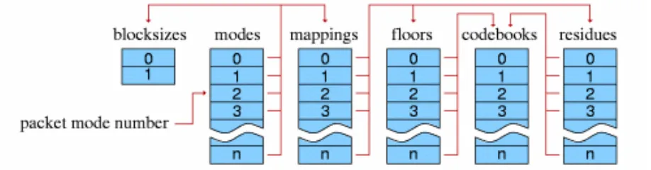
Decoder setup consists of configuration of multiple, self-contained component abstractions that perform specific functions in the decode pipeline. Each different component instance of a specific type is semantically interchangeable; decoder configuration consists both of internal component configuration, as well as arrangement of specific instances into a decode pipeline. Componentry arrangement is roughly as follows:
1.2.1. Global Config
Global codec configuration consists of a few audio related fields (sample rate, channels), Vorbis version (always ’0’ in Vorbis I), bitrate hints, and the lists of component instances. All other configuration is in the context of specific components.
1.2.2. Mode
Each Vorbis frame is coded according to a master ’mode’. A bitstream may use one or many modes.
The mode mechanism is used to encode a frame according to one of multiple possible methods with the intention of choosing a method best suited to that frame. Different modes are, e.g. how frame size is changed from frame to frame. The mode number of a frame serves as a top level configuration switch for all other specific aspects of frame decode.
A ’mode’ configuration consists of a frame size setting, window type (always 0, the Vorbis window, in Vorbis I), transform type (always type 0, the MDCT, in Vorbis I) and a mapping number. The mapping number specifies which mapping configuration instance to use for low-level packet decode and synthesis.
1.2.3. Mapping
A mapping contains a channel coupling description and a list of ’submaps’ that bundle sets of channel vectors together for grouped encoding and decoding. These submaps are not references to external components; the submap list is internal and specific to a mapping.
A ’submap’ is a configuration/grouping that applies to a subset of floor and residue vectors within a mapping. The submap functions as a last layer of indirection such that specific special floor or residue settings can be applied not only to all the vectors in a given mode, but also specific vectors in a specific mode. Each submap specifies the proper floor and residue instance number to use for decoding that submap’s spectral floor and spectral residue vectors.
As an example:
1.2.4. Floor
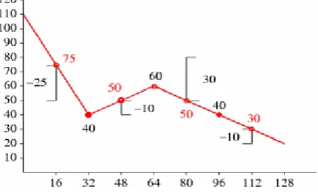
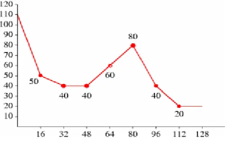
Vorbis encodes a spectral ’floor’ vector for each PCM channel. This vector is a low-resolution representation of the audio spectrum for the given channel in the current frame, generally used akin to a whitening filter. It is named a ’floor’ because the Xiph.Org reference encoder has historically used it as a unit-baseline for spectral resolution.
A floor encoding may be of two types. Floor 0 uses a packed LSP representation on a dB amplitude scale and Bark frequency scale. Floor 1 represents the curve as a piecewise linear interpolated representation on a dB amplitude scale and linear frequency scale. The two floors are semantically interchangeable in encoding/decoding. However, floor type 1 provides more stable inter-frame behavior, and so is the preferred choice in all coupled-stereo and high bitrate modes. Floor 1 is also considerably less expensive to decode than floor 0.
Floor 0 is not to be considered deprecated, but it is of limited modern use. No known Vorbis encoder past Xiph.Org’s own beta 4 makes use of floor 0.
The values coded/decoded by a floor are both compactly formatted and make use of en-tropy coding to save space. For this reason, a floor configuration generally refers to mul-tiple codebooks in the codebook component list. Entropy coding is thus provided as an abstraction, and each floor instance may choose from any and all available codebooks when coding/decoding.
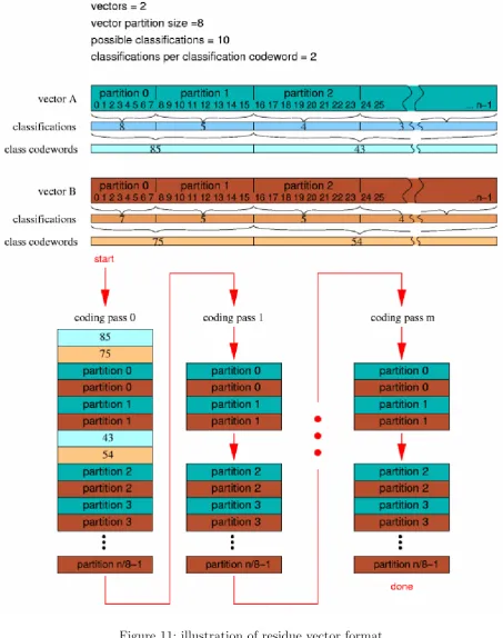
1.2.5. Residue
The spectral residue is the fine structure of the audio spectrum once the floor curve has been subtracted out. In simplest terms, it is coded in the bitstream using cascaded (multi-pass) vector quantization according to one of three specific packing/coding algorithms numbered 0 through 2. The packing algorithm details are configured by residue instance. As with the floor components, the final VQ/entropy encoding is provided by external codebook instances and each residue instance may choose from any and all available codebooks.
1.2.6. Codebooks
Codebooks are a self-contained abstraction that perform entropy decoding and, optionally, use the entropy-decoded integer value as an offset into an index of output value vectors, returning the indicated vector of values.
The codebook vector index is similarly packed according to index characteristic. Most commonly, the vector index is encoded as a single list of values of possible values that are then permuted into a list of n-dimensional rows (lattice VQ).
1.3. High-level Decode Process
1.3.1. Decode Setup
Before decoding can begin, a decoder must initialize using the bitstream headers matching the stream to be decoded. Vorbis uses three header packets; all are required, in-order, by this specification. Once set up, decode may begin at any audio packet belonging to the Vorbis stream. In Vorbis I, all packets after the three initial headers are audio packets.
The header packets are, in order, the identification header, the comments header, and the setup header.
Identification Header The identification header identifies the bitstream as Vorbis, Vorbis version, and the simple audio characteristics of the stream such as sample rate and number of channels.
Comment Header The comment header includes user text comments (“tags”) and a vendor string for the application/library that produced the bitstream. The encoding and proper use of the comment header is described in section 5, “comment field and header specification”.
Setup Header The setup header includes extensive CODEC setup information as well as the complete VQ and Huffman codebooks needed for decode.
1.3.2. Decode Procedure
The decoding and synthesis procedure for all audio packets is fundamentally the same.
1. decode packet type flag
2. decode mode number
3. decode window shape (long windows only)
4. decode floor
6. inverse channel coupling of residue vectors
7. generate floor curve from decoded floor data
8. compute dot product of floor and residue, producing audio spectrum vector
9. inverse monolithic transform of audio spectrum vector, always an MDCT in Vorbis I
10. overlap/add left-hand output of transform with right-hand output of previous frame
11. store right hand-data from transform of current frame for future lapping
12. if not first frame, return results of overlap/add as audio result of current frame
Note that clever rearrangement of the synthesis arithmetic is possible; as an example, one can take advantage of symmetries in the MDCT to store the right-hand transform data of a partial MDCT for a 50% inter-frame buffer space savings, and then complete the transform later before overlap/add with the next frame. This optimization produces entirely equiva-lent output and is naturally perfectly legal. The decoder must be entirely mathematically equivalent to the specification, it need not be a literal semantic implementation.
Packet type decode Vorbis I uses four packet types. The first three packet types mark each of the three Vorbis headers described above. The fourth packet type marks an audio packet. All other packet types are reserved; packets marked with a reserved type should be ignored.
Following the three header packets, all packets in a Vorbis I stream are audio. The first step of audio packet decode is to read and verify the packet type;a non-audio packet when audio is expected indicates stream corruption or a non-compliant stream. The decoder must ignore the packet and not attempt decoding it to audio.
Mode decode Vorbis allows an encoder to set up multiple, numbered packet ’modes’, as described earlier, all of which may be used in a given Vorbis stream. The mode is encoded as an integer used as a direct offset into the mode instance index.
Window shape decode (long windows only) Vorbis frames may be one of two PCM sample sizes specified during codec setup. In Vorbis I, legal frame sizes are powers of two from 64 to 8192 samples. Aside from coupling, Vorbis handles channels as independent vectors and these frame sizes are in samples per channel.
Vorbis uses an overlapping transform, namely the MDCT, to blend one frame into the next, avoiding most inter-frame block boundary artifacts. The MDCT output of one frame is windowed according to MDCT requirements, overlapped 50% with the output of the previous frame and added. The window shape assures seamless reconstruction.
Figure 2: overlap of two equal-sized windows
And slightly more complex in the case of overlapping unequal sized windows:
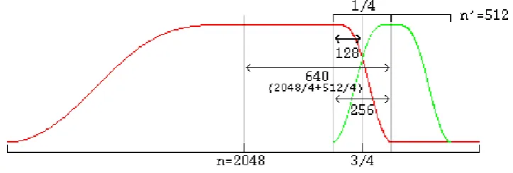
Figure 3: overlap of a long and a short window
In the unequal-sized window case, the window shape of the long window must be modified for seamless lapping as above. It is possible to correctly infer window shape to be applied to the current window from knowing the sizes of the current, previous and next window. It is legal for a decoder to use this method. However, in the case of a long window (short windows require no modification), Vorbis also codes two flag bits to specify pre- and post-window shape. Although not strictly necessary for function, this minor redundancy allows a packet to be fully decoded to the point of lapping entirely independently of any other packet, allowing easier abstraction of decode layers as well as allowing a greater level of easy parallelism in encode and decode.
A description of valid window functions for use with an inverse MDCT can be found in [1]. Vorbis windows all use the slope function
y= sin(.5∗π sin2
((x+.5)/n∗π)).
residue decode Although the number of residue vectors equals the number of channels, channel coupling may mean that the raw residue vectors extracted during decode do not map directly to specific channels. When channel coupling is in use, some vectors will correspond to coupled magnitude or angle. The coupling relationships are described in the codec setup and may differ from frame to frame, due to different mode numbers.
Vorbis codes residue vectors in groups by submap; the coding is done in submap order from submap 0 through n-1. This differs from floors which are coded using a configuration provided by submap number, but are coded individually in channel order.
inverse channel coupling A detailed discussion of stereo in the Vorbis codec can be found in the document Stereo Channel Coupling in the Vorbis CODEC. Vorbis is not limited to only stereo coupling, but the stereo document also gives a good overview of the generic coupling mechanism.
Vorbis coupling applies to pairs of residue vectors at a time; decoupling is done in-place a pair at a time in the order and using the vectors specified in the current mapping configuration. The decoupling operation is the same for all pairs, converting square polar representation (where one vector is magnitude and the second angle) back to Cartesian representation.
After decoupling, in order, each pair of vectors on the coupling list, the resulting residue vectors represent the fine spectral detail of each output channel.
generate floor curve The decoder may choose to generate the floor curve at any appropri-ate time. It is reasonable to generappropri-ate the output curve when the floor data is decoded from the raw packet, or it can be generated after inverse coupling and applied to the spectral residue directly, combining generation and the dot product into one step and eliminating some working space.
Both floor 0 and floor 1 generate a linear-range, linear-domain output vector to be multi-plied (dot product) by the linear-range, linear-domain spectral residue.
compute floor/residue dot product This step is straightforward; for each output chan-nel, the decoder multiplies the floor curve and residue vectors element by element, produc-ing the finished audio spectrum of each channel.
One point is worth mentioning about this dot product; a common mistake in a fixed point implementation might be to assume that a 32 bit fixed-point representation for floor and residue and direct multiplication of the vectors is sufficient for acceptable spectral depth in all cases because it happens to mostly work with the current Xiph.Org reference encoder.
a 16 bit PCM device. For the residue vector to represent full scale if the floor is nailed to
−140dB, it must be able to span 0 to +140dB. For the residue vector to reach full scale if
the floor is nailed at 0dB, it must be able to represent−140dB to +0dB. Thus, in order to handle full range dynamics, a residue vector may span−140dB to +140dB entirely within spec. A 280dB range is approximately 48 bits with sign; thus the residue vector must be able to represent a 48 bit range and the dot product must be able to handle an effective 48 bit times 24 bit multiplication. This range may be achieved using large (64 bit or larger) integers, or implementing a movable binary point representation.
inverse monolithic transform (MDCT) The audio spectrum is converted back into time domain PCM audio via an inverse Modified Discrete Cosine Transform (MDCT). A detailed description of the MDCT is available in [1].
Note that the PCM produced directly from the MDCT is not yet finished audio; it must be lapped with surrounding frames using an appropriate window (such as the Vorbis window) before the MDCT can be considered orthogonal.
overlap/add data Windowed MDCT output is overlapped and added with the right hand data of the previous window such that the 3/4 point of the previous window is aligned with the 1/4 point of the current window (as illustrated in the window overlap diagram). At this point, the audio data between the center of the previous frame and the center of the current frame is now finished and ready to be returned.
cache right hand data The decoder must cache the right hand portion of the current frame to be lapped with the left hand portion of the next frame.
return finished audio data The overlapped portion produced from overlapping the pre-vious and current frame data is finished data to be returned by the decoder. This data spans from the center of the previous window to the center of the current window. In the case of same-sized windows, the amount of data to return is one-half block consisting of and only of the overlapped portions. When overlapping a short and long window, much of the returned range is not actually overlap. This does not damage transform orthogonal-ity. Pay attention however to returning the correct data range; the amount of data to be returned is:
1 window_blocksize(previous_window)/4+window_blocksize(current_window)/4
from the center of the previous window to the center of the current window.
2. Bitpacking Convention
2.1. Overview
The Vorbis codec uses relatively unstructured raw packets containing arbitrary-width bi-nary integer fields. Logically, these packets are a bitstream in which bits are coded one-by-one by the encoder and then read one-by-one-by-one-by-one in the same monotonically increasing order by the decoder. Most current binary storage arrangements group bits into a native word size of eight bits (octets), sixteen bits, thirty-two bits or, less commonly other fixed word sizes. The Vorbis bitpacking convention specifies the correct mapping of the logical packet bitstream into an actual representation in fixed-width words.
2.1.1. octets, bytes and words
In most contemporary architectures, a ’byte’ is synonymous with an ’octet’, that is, eight bits. This has not always been the case; seven, ten, eleven and sixteen bit ’bytes’ have been used. For purposes of the bitpacking convention, a byte implies the native, smallest integer storage representation offered by a platform. On modern platforms, this is gen-erally assumed to be eight bits (not necessarily because of the processor but because of the filesystem/memory architecture. Modern filesystems invariably offer bytes as the fun-damental atom of storage). A ’word’ is an integer size that is a grouped multiple of this smallest size.
The most ubiquitous architectures today consider a ’byte’ to be an octet (eight bits) and a word to be a group of two, four or eight bytes (16, 32 or 64 bits). Note however that the Vorbis bitpacking convention is still well defined for any native byte size; Vorbis uses the native bit-width of a given storage system. This document assumes that a byte is one octet for purposes of example.
2.1.2. bit order
A byte has a well-defined ’least significant’ bit (LSb), which is the only bit set when the byte is storing the two’s complement integer value +1. A byte’s ’most significant’ bit (MSb) is at the opposite end of the byte. Bits in a byte are numbered from zero at the LSb to n (n= 7 in an octet) for the MSb.
2.1.3. byte order
the highest-valued byte comes first), 0-1-2-3 (’little endian’ or ’least significant byte first’ in which the lowest value byte comes first) and less commonly 3-1-2-0 and 0-2-1-3 (’mixed endian’).
The Vorbis bitpacking convention specifies storage and bitstream manipulation at the byte, not word, level, thus host word ordering is of a concern only during optimization when writing high performance code that operates on a word of storage at a time rather than by byte. Logically, bytes are always coded and decoded in order from byte zero through byte n.
2.1.4. coding bits into byte sequences
The Vorbis codec has need to code arbitrary bit-width integers, from zero to 32 bits wide, into packets. These integer fields are not aligned to the boundaries of the byte representa-tion; the next field is written at the bit position at which the previous field ends.
The encoder logically packs integers by writing the LSb of a binary integer to the logical bitstream first, followed by next least significant bit, etc, until the requested number of bits have been coded. When packing the bits into bytes, the encoder begins by placing the LSb of the integer to be written into the least significant unused bit position of the destination byte, followed by the next-least significant bit of the source integer and so on up to the requested number of bits. When all bits of the destination byte have been filled, encoding continues by zeroing all bits of the next byte and writing the next bit into the bit position 0 of that byte. Decoding follows the same process as encoding, but by reading bits from the byte stream and reassembling them into integers.
2.1.5. signedness
The signedness of a specific number resulting from decode is to be interpreted by the decoder given decode context. That is, the three bit binary pattern ’b111’ can be taken to represent either ’seven’ as an unsigned integer, or ’-1’ as a signed, two’s complement integer. The encoder and decoder are responsible for knowing if fields are to be treated as signed or unsigned.
2.1.6. coding example
Code the 4 bit integer value ’12’ [b1100] into an empty bytestream. Bytestream result:
1 |
2 V
3
7 byte 2 [ ] 8 byte 3 [ ]
9 ...
10 byte n [ ] bytestream length == 1 byte 11
Continue by coding the 3 bit integer value ’-1’ [b111]:
1 |
Continue by coding the 7 bit integer value ’17’ [b0010001]:
1 |
Continue by coding the 13 bit integer value ’6969’ [b110 11001110 01]:
1 |
Reading from the beginning of the bytestream encoded in the above example:
We read two, two-bit integer fields, resulting in the returned numbers ’b00’ and ’b11’. Two things are worth noting here:
• Although these four bits were originally written as a single four-bit integer, reading
some other combination of bit-widths from the bitstream is well defined. There are no artificial alignment boundaries maintained in the bitstream.
• The second value is the two-bit-wide integer ’b11’. This value may be interpreted
either as the unsigned value ’3’, or the signed value ’-1’. Signedness is dependent on decode context.
2.1.8. end-of-packet alignment
The typical use of bitpacking is to produce many independent byte-aligned packets which are embedded into a larger byte-aligned container structure, such as an Ogg transport bitstream. Externally, each bytestream (encoded bitstream) must begin and end on a byte boundary. Often, the encoded bitstream is not an integer number of bytes, and so there is unused (uncoded) space in the last byte of a packet.
Unused space in the last byte of a bytestream is always zeroed during the coding process. Thus, should this unused space be read, it will return binary zeroes.
Attempting to read past the end of an encoded packet results in an ’end-of-packet’ condi-tion. End-of-packet is not to be considered an error; it is merely a state indicating that there is insufficient remaining data to fulfill the desired read size. Vorbis uses truncated packets as a normal mode of operation, and as such, decoders must handle reading past the end of a packet as a typical mode of operation. Any further read operations after an ’end-of-packet’ condition shall also return ’end-of-packet’.
2.1.9. reading zero bits
3. Probability Model and Codebooks
3.1. Overview
Unlike practically every other mainstream audio codec, Vorbis has no statically configured probability model, instead packing all entropy decoding configuration, VQ and Huffman, into the bitstream itself in the third header, the codec setup header. This packed con-figuration consists of multiple ’codebooks’, each containing a specific Huffman-equivalent representation for decoding compressed codewords as well as an optional lookup table of output vector values to which a decoded Huffman value is applied as an offset, generating the final decoded output corresponding to a given compressed codeword.
3.1.1. Bitwise operation
The codebook mechanism is built on top of the vorbis bitpacker. Both the codebooks them-selves and the codewords they decode are unrolled from a packet as a series of arbitrary-width values read from the stream according to section 2, “Bitpacking Convention”.
3.2. Packed codebook format
For purposes of the examples below, we assume that the storage system’s native byte width is eight bits. This is not universally true; seesection 2, “Bitpacking Convention” for discussion relating to non-eight-bit bytes.
3.2.1. codebook decode
A codebook begins with a 24 bit sync pattern, 0x564342:
1 byte 0: [ 0 1 0 0 0 0 1 0 ] (0x42) 2 byte 1: [ 0 1 0 0 0 0 1 1 ] (0x43) 3 byte 2: [ 0 1 0 1 0 1 1 0 ] (0x56)
16 bit [codebook_dimensions]and 24 bit [codebook_entries] fields:
1
2 byte 3: [ X X X X X X X X ]
3 byte 4: [ X X X X X X X X ] [codebook_dimensions] (16 bit unsigned) 4
5 byte 5: [ X X X X X X X X ] 6 byte 6: [ X X X X X X X X ]
7 byte 7: [ X X X X X X X X ] [codebook_entries] (24 bit unsigned) 8
1
2 byte 8: [ X ] [ordered] (1 bit) 3
Each entry, numbering a total of [codebook_entries], is assigned a codeword length. We now read the list of codeword lengths and store these lengths in the array[codebook_
codeword_lengths]. Decode of lengths is according to whether the[ordered] flag is set
or unset.
• If the[ordered]flag is unset, the codeword list is not length ordered and the decoder
needs to read each codeword length one-by-one.
The decoder first reads one additional bit flag, the [sparse] flag. This flag de-termines whether or not the codebook contains unused entries that are not to be included in the codeword decode tree:
1 byte 8: [ X 1 ] [sparse] flag (1 bit)
The decoder now performs for each of the[codebook_entries] codebook entries:
1
7 4) [length] = read a five bit unsigned integer; 8 5) codeword length for this entry is [length]+1; 9
10 } else {
11
12 6) this entry is unused. mark it as such. 13
14 }
15
16 } else the sparse flag is not set { 17
18 7) [length] = read a five bit unsigned integer; 19 8) the codeword length for this entry is [length]+1; 20
21 }
22
• If the [ordered] flag is set, the codeword list for this codebook is encoded in
as-cending length order. Rather than reading a length for every codeword, the encoder reads the number of codewords per length. That is, beginning at entry zero:
1 1) [current_entry] = 0;
2 2) [current_length] = read a five bit unsigned integer and add 1;
3 3) [number] = read ilog([codebook_entries] - [current_entry]) bits as an unsigned integer 4 4) set the entries [current_entry] through [current_entry]+[number]-1, inclusive,
5 of the [codebook_codeword_lengths] array to [current_length] 6 5) set [current_entry] to [number] + [current_entry]
7 6) increment [current_length] by 1
8 7) if [current_entry] is greater than [codebook_entries] ERROR CONDITION; 9 the decoder will not be able to read this stream.
After all codeword lengths have been decoded, the decoder reads the vector lookup table. Vorbis I supports three lookup types:
1. No lookup
2. Implicitly populated value mapping (lattice VQ)
3. Explicitly populated value mapping (tessellated or ’foam’ VQ)
The lookup table type is read as a four bit unsigned integer:
1 1) [codebook_lookup_type] = read four bits as an unsigned integer
Codebook decode precedes according to [codebook_lookup_type]:
• Lookup type zero indicates no lookup to be read. Proceed past lookup decode.
• Lookup types one and two are similar, differing only in the number of lookup values to
be read. Lookup type one reads a list of values that are permuted in a set pattern to build a list of vectors, each vector of order[codebook_dimensions]scalars. Lookup type two builds the same vector list, but reads each scalar for each vector explicitly, rather than building vectors from a smaller list of possible scalar values. Lookup decode proceeds as follows:
1 1) [codebook_minimum_value] = float32_unpack( read 32 bits as an unsigned integer) 2 2) [codebook_delta_value] = float32_unpack( read 32 bits as an unsigned integer) 3 3) [codebook_value_bits] = read 4 bits as an unsigned integer and add 1
4 4) [codebook_sequence_p] = read 1 bit as a boolean flag 5
6 if ( [codebook_lookup_type] is 1 ) { 7
8 5) [codebook_lookup_values] = lookup1_values([codebook_entries], [codebook_dimensions] ) 9
10 } else { 11
12 6) [codebook_lookup_values] = [codebook_entries] * [codebook_dimensions] 13
14 }
15
16 7) read a total of [codebook_lookup_values] unsigned integers of [codebook_value_bits] each; 17 store these in order in the array [codebook_multiplicands]
• A [codebook_lookup_type] of greater than two is reserved and indicates a stream
that is not decodable by the specification in this document.
An ’end of packet’ during any read operation in the above steps is considered an error condition rendering the stream undecodable.
Huffman decision tree representation The [codebook_codeword_lengths] array and
[codebook_entries] value uniquely define the Huffman decision tree used for entropy
decoding.
possible. Assume the following codeword length list:
1 entry 0: length 2 2 entry 1: length 4 3 entry 2: length 4 4 entry 3: length 4 5 entry 4: length 4 6 entry 5: length 2 7 entry 6: length 3 8 entry 7: length 3
Assigning codewords in order (lowest possible value of the appropriate length to highest) results in the following codeword list:
1 entry 0: length 2 codeword 00 2 entry 1: length 4 codeword 0100 3 entry 2: length 4 codeword 0101 4 entry 3: length 4 codeword 0110 5 entry 4: length 4 codeword 0111 6 entry 5: length 2 codeword 10 7 entry 6: length 3 codeword 110 8 entry 7: length 3 codeword 111
Note: Unlike most binary numerical values in this document, we intend the above code-words to be read and used bit by bit from left to right, thus the codeword ’001’ is the bit string ’zero, zero, one’. When determining ’lowest possible value’ in the assignment definition above, the leftmost bit is the MSb.
It is clear that the codeword length list represents a Huffman decision tree with the entry numbers equivalent to the leaves numbered left-to-right:
Figure 4: huffman tree illustration
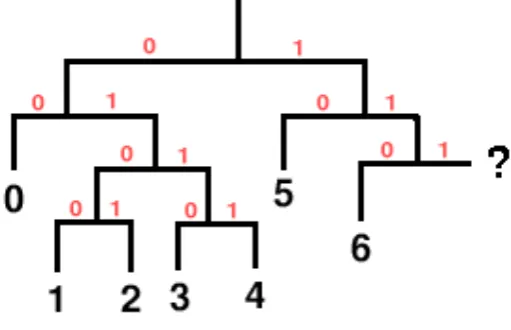
Note that it’s possible to underspecify or overspecify a Huffman tree via the length list. In the above example, if codeword seven were eliminated, it’s clear that the tree is unfinished:
Figure 5: underspecified huffman tree illustration
Similarly, in the original codebook, it’s clear that the tree is fully populated and a ninth codeword is impossible. Both underspecified and overspecified trees are an error condition rendering the stream undecodable.
Codebook entries marked ’unused’ are simply skipped in the assigning process. They have no codeword and do not appear in the decision tree, thus it’s impossible for any bit pattern read from the stream to decode to that entry number.
Errata 20150226: Single entry codebooks A ’single-entry codebook’ is a codebook with one active codeword entry. A single-entry codebook may be either a fully populated codebook with only one declared entry, or a sparse codebook with only one entry marked used. The Vorbis I spec provides no means to specify a codeword length of zero, and as a result, a single-entry codebook is inherently malformed because it is underpopulated. The original specification did not address directly the matter of single-entry codebooks; they were implicitly illegal as it was not possible to write such a codebook with a valid tree structure.
In r14811 of the libvorbis reference implementation, Xiph added an additional check to the codebook implementation to reject underpopulated Huffman trees. This change led to the discovery of single-entry books used ’in the wild’ when the new, stricter checks rejected a number of apparently working streams.
“Take special care that a codebook with a single used entry is handled properly; it consists of a single codework of zero bits and reading a value out of such a codebook always returns the single used value and sinks zero bits. ”
The intent was to clarify the spec and codify current practice. However, this addition is erroneously at odds with the intent of preserving usability of existing streams using single-entry codebooks, disagrees with the code changes that reinstated decoding, and does not address how single-entry codebooks should be encoded.
As such, the above addition made in r16037 is struck from the specification and replaced by the following:
It is possible to declare a Vorbis codebook containing a single codework en-try. A single-entry codebook may be either a fully populated codebook with
[codebook_entries] set to 1, or a sparse codebook marking only one entry
used. Note that it is not possible to also encode a [codeword_length] of zero for the single used codeword, as the unsigned value written to the stream is
[codeword_length]-1. Instead, encoder implementations should indicate a
[codeword_length] of 1 and ’write’ the codeword to a stream during audio
encoding by writing a single zero bit.
Decoder implementations shall reject a codebook if it contains only one used entry and the encoded[codeword_length] of that entry is not 1. ’Reading’ a value from single-entry codebook always returns the single used codeword value and sinks one bit. Decoders should tolerate that the bit read from the stream be ’1’ instead of ’0’; both values shall return the single used codeword.
VQ lookup table vector representation Unpacking the VQ lookup table vectors relies on the following values:
Decoding (unpacking) a specific vector in the vector lookup table proceeds according to
[codebook_lookup_type]. The unpacked vector values are what a codebook would return
during audio packet decode in a VQ context.
([value_vector] is the output vector representing the vector of values for entry number
[lookup_offset] in this codebook):
1 1) [last] = 0;
2 2) [index_divisor] = 1;
3 3) iterate [i] over the range 0 ... [codebook_dimensions]-1 (once for each scalar value in the value vector) { 4
5 4) [multiplicand_offset] = ( [lookup_offset] divided by [index_divisor] using integer 6 division ) integer modulo [codebook_lookup_values]
7
8 5) vector [value_vector] element [i] =
9 ( [codebook_multiplicands] array element number [multiplicand_offset] ) * 10 [codebook_delta_value] + [codebook_minimum_value] + [last];
11
12 6) if ( [codebook_sequence_p] is set ) then set [last] = vector [value_vector] element [i] 13
14 7) [index_divisor] = [index_divisor] * [codebook_lookup_values] 15
16 }
17
18 8) vector calculation completed.
Vector value decode: Lookup type 2 Lookup type two specifies a VQ lookup table in which each scalar in each vector is explicitly set by the [codebook_multiplicands]
array in a one-to-one mapping. Calculate [unpack] the final values of a codebook entry vector from the entries in [codebook_multiplicands] as follows ([value_vector] is the output vector representing the vector of values for entry number[lookup_offset] in this codebook):
1 1) [last] = 0;
2 2) [multiplicand_offset] = [lookup_offset] * [codebook_dimensions]
3 3) iterate [i] over the range 0 ... [codebook_dimensions]-1 (once for each scalar value in the value vector) { 4
5 4) vector [value_vector] element [i] =
6 ( [codebook_multiplicands] array element number [multiplicand_offset] ) * 7 [codebook_delta_value] + [codebook_minimum_value] + [last];
8
9 5) if ( [codebook_sequence_p] is set ) then set [last] = vector [value_vector] element [i] 10
3.3. Use of the codebook abstraction
or a lookup vector.
Note that VQ lookup type zero indicates that there is no lookup table; requesting decode using a codebook of lookup type 0 in any context expecting a vector return value (even in a case where a vector of dimension one) is forbidden. If decoder setup or decode requests such an action, that is an error condition rendering the packet undecodable.
Using a codebook to read from the packet bitstream consists first of reading and decoding the next codeword in the bitstream. The decoder reads bits until the accumulated bits match a codeword in the codebook. This process can be though of as logically walking the Huffman decode tree by reading one bit at a time from the bitstream, and using the bit as a decision boolean to take the 0 branch (left in the above examples) or the 1 branch (right in the above examples). Walking the tree finishes when the decode process hits a leaf in the decision tree; the result is the entry number corresponding to that leaf. Reading past the end of a packet propagates the ’end-of-stream’ condition to the decoder.
When used in a scalar context, the resulting codeword entry is the desired return value.
4. Codec Setup and Packet Decode
4.1. Overview
This document serves as the top-level reference document for the bit-by-bit decode specifi-cation of Vorbis I. This document assumes a high-level understanding of the Vorbis decode process, which is provided in section 1, “Introduction and Description”. section 2, “ Bit-packing Convention” covers reading and writing bit fields from and to bitstream packets.
4.2. Header decode and decode setup
A Vorbis bitstream begins with three header packets. The header packets are, in order, the identification header, the comments header, and the setup header. All are required for decode compliance. An end-of-packet condition during decoding the first or third header packet renders the stream undecodable. End-of-packet decoding the comment header is a non-fatal error condition.
4.2.1. Common header decode
Each header packet begins with the same header fields.
1 1) [packet_type] : 8 bit value
2 2) 0x76, 0x6f, 0x72, 0x62, 0x69, 0x73: the characters ’v’,’o’,’r’,’b’,’i’,’s’ as six octets
Decode continues according to packet type; the identification header is type 1, the comment header type 3 and the setup header type 5 (these types are all odd as a packet with a leading single bit of ’0’ is an audio packet). The packets must occur in the order of identification, comment, setup.
4.2.2. Identification header
The identification header is a short header of only a few fields used to declare the stream definitively as Vorbis, and provide a few externally relevant pieces of information about the audio stream. The identification header is coded as follows:
1 1) [vorbis_version] = read 32 bits as unsigned integer 2 2) [audio_channels] = read 8 bit integer as unsigned 3 3) [audio_sample_rate] = read 32 bits as unsigned integer 4 4) [bitrate_maximum] = read 32 bits as signed integer 5 5) [bitrate_nominal] = read 32 bits as signed integer 6 6) [bitrate_minimum] = read 32 bits as signed integer
[vorbis_version] is to read ’0’ in order to be compatible with this document. Both
[audio_channels]and[audio_sample_rate]must read greater than zero. Allowed final
blocksize values are 64, 128, 256, 512, 1024, 2048, 4096 and 8192 in Vorbis I.[blocksize_ 0]must be less than or equal to[blocksize_1]. The framing bit must be nonzero. Failure to meet any of these conditions renders a stream undecodable.
The bitrate fields above are used only as hints. The nominal bitrate field especially may be considerably off in purely VBR streams. The fields are meaningful only when greater than zero.
• All three fields set to the same value implies a fixed rate, or tightly bounded, nearly
fixed-rate bitstream
• Only nominal set implies a VBR or ABR stream that averages the nominal bitrate
• Maximum and or minimum set implies a VBR bitstream that obeys the bitrate limits
• None set indicates the encoder does not care to speculate.
4.2.3. Comment header
Comment header decode and data specification is covered insection 5, “comment field and header specification”.
4.2.4. Setup header
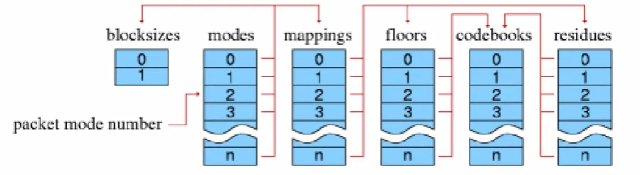
Vorbis codec setup is configurable to an extreme degree:
Figure 6: decoder pipeline configuration
Codebooks
1. [vorbis_codebook_count] = read eight bits as unsigned integer and add one
2. Decode[vorbis_codebook_count]codebooks in order as defined insection 3, “ Prob-ability Model and Codebooks”. Save each configuration, in order, in an array of codebook configurations [vorbis_codebook_configurations].
Time domain transforms These hooks are placeholders in Vorbis I. Nevertheless, the configuration placeholder values must be read to maintain bitstream sync.
1. [vorbis_time_count] = read 6 bits as unsigned integer and add one
2. read [vorbis_time_count] 16 bit values; each value should be zero. If any value is nonzero, this is an error condition and the stream is undecodable.
Floors Vorbis uses two floor types; header decode is handed to the decode abstraction of the appropriate type.
1. [vorbis_floor_count]= read 6 bits as unsigned integer and add one
2. For each [i]of [vorbis_floor_count]floor numbers:
a) read the floor type: vector[vorbis_floor_types] element[i] = read 16 bits as unsigned integer
b) If the floor type is zero, decode the floor configuration as defined in section 6, “Floor type 0 setup and decode”; save this configuration in slot [i]of the floor configuration array [vorbis_floor_configurations].
c) If the floor type is one, decode the floor configuration as defined in section 7, “Floor type 1 setup and decode”; save this configuration in slot [i]of the floor configuration array [vorbis_floor_configurations].
d) If the the floor type is greater than one, this stream is undecodable; ERROR CONDITION
Residues Vorbis uses three residue types; header decode of each type is identical.
1. [vorbis_residue_count] = read 6 bits as unsigned integer and add one
2. For each of [vorbis_residue_count] residue numbers:
b) If the residue type is zero, one or two, decode the residue configuration as defined insection 8, “Residue setup and decode”; save this configuration in slot [i]of the residue configuration array [vorbis_residue_configurations].
c) If the the residue type is greater than two, this stream is undecodable; ERROR CONDITION
Mappings Mappings are used to set up specific pipelines for encoding multichannel audio with varying channel mapping applications. Vorbis I uses a single mapping type (0), with implicit PCM channel mappings.
1. [vorbis_mapping_count] = read 6 bits as unsigned integer and add one
2. For each [i]of [vorbis_mapping_count] mapping numbers:
a) read the mapping type: 16 bits as unsigned integer. There’s no reason to save the mapping type in Vorbis I.
b) If the mapping type is nonzero, the stream is undecodable
c) If the mapping type is zero:
i. read 1 bit as a boolean flag
A. if set, [vorbis_mapping_submaps] = read 4 bits as unsigned integer and add one
B. if unset, [vorbis_mapping_submaps] = 1
ii. read 1 bit as a boolean flag
A. if set, square polar channel mapping is in use:
• [vorbis_mapping_coupling_steps]= read 8 bits as unsigned
inte-ger and add one
• for [j]each of [vorbis_mapping_coupling_steps] steps:
– vector[vorbis_mapping_magnitude]element[j]= readilog([audio_
channels] - 1) bits as unsigned integer
– vector[vorbis_mapping_angle] element[j]= readilog([audio_
channels] - 1) bits as unsigned integer
– the numbers read in the above two steps are channel numbers
channel is greater than [audio_channels]-1, the stream is unde-codable.
B. if unset, [vorbis_mapping_coupling_steps] = 0
iii. read 2 bits (reserved field); if the value is nonzero, the stream is undecodable
iv. if [vorbis_mapping_submaps] is greater than one, we read channel multi-plex settings. For each [j] of [audio_channels] channels:
A. vector [vorbis_mapping_mux] element [j] = read 4 bits as unsigned integer
B. if the value is greater than the highest numbered submap ([vorbis_
mapping_submaps]- 1), this in an error condition rendering the stream
undecodable
v. for each submap [j] of [vorbis_mapping_submaps] submaps, read the floor and residue numbers for use in decoding that submap:
A. read and discard 8 bits (the unused time configuration placeholder)
B. read 8 bits as unsigned integer for the floor number; save in vector
[vorbis_mapping_submap_floor] element [j]
C. verify the floor number is not greater than the highest number floor configured for the bitstream. If it is, the bitstream is undecodable
D. read 8 bits as unsigned integer for the residue number; save in vector
[vorbis_mapping_submap_residue] element [j]
E. verify the residue number is not greater than the highest number residue configured for the bitstream. If it is, the bitstream is undecodable
vi. save this mapping configuration in slot [i] of the mapping configuration array [vorbis_mapping_configurations].
Modes
1. [vorbis_mode_count] = read 6 bits as unsigned integer and add one
2. For each of [vorbis_mode_count] mode numbers:
a) [vorbis_mode_blockflag] = read 1 bit
b) [vorbis_mode_windowtype] = read 16 bits as unsigned integer
c) [vorbis_mode_transformtype] = read 16 bits as unsigned integer
e) verify ranges; zero is the only legal value in Vorbis I for[vorbis_mode_windowtype]
and [vorbis_mode_transformtype]. [vorbis_mode_mapping] must not be
greater than the highest number mapping in use. Any illegal values render the stream undecodable.
f) save this mode configuration in slot[i]of the mode configuration array[vorbis_
mode_configurations].
3. read 1 bit as a framing flag. If unset, a framing error occurred and the stream is not decodable.
After reading mode descriptions, setup header decode is complete.
4.3. Audio packet decode and synthesis
Following the three header packets, all packets in a Vorbis I stream are audio. The first step of audio packet decode is to read and verify the packet type. A non-audio packet when audio is expected indicates stream corruption or a non-compliant stream. The decoder must ignore the packet and not attempt decoding it to audio.
4.3.1. packet type, mode and window decode
1. read 1 bit [packet_type]; check that packet type is 0 (audio)
2. read ilog([vorbis mode count]-1) bits [mode_number]
3. decode blocksize [n] is equal to[blocksize_0] if [vorbis_mode_blockflag] is 0, else [n] is equal to[blocksize_1].
4. perform window selection and setup; this window is used later by the inverse MDCT:
a) if this is a long window (the [vorbis_mode_blockflag] flag of this mode is set):
i. read 1 bit for [previous_window_flag]
ii. read 1 bit for [next_window_flag]
iii. if [previous_window_flag] is not set, the left half of the window will be a hybrid window for lapping with a short block. See section 1.3.2, “ Win-dow shape decode (long winWin-dows only)” for an illustration of overlapping dissimilar windows. Else, the left half window will have normal long shape.
b) if this is a short window, the window is always the same short-window shape.
Vorbis windows all use the slope function y = sin(π
2 ∗sin 2
((x+ 0.5)/n∗π)), where n is
window size and xranges 0. . . n−1, but dissimilar lapping requirements can affect overall shape. Window generation proceeds as follows:
1. [window_center] = [n]/ 2
2. if ([vorbis_mode_blockflag] is set and[previous_window_flag] is not set) then
a) [left_window_start] =[n]/4 - [blocksize_0]/4
b) [left_window_end]= [n]/4 + [blocksize_0]/4
c) [left_n]= [blocksize_0]/2
else
a) [left_window_start] = 0
b) [left_window_end]= [window_center]
c) [left_n]= [n]/2
3. if ([vorbis_mode_blockflag] is set and [next_window_flag] is not set) then
a) [right_window_start]=[n]*3/4 - [blocksize_0]/4
b) [right_window_end]= [n]*3/4 + [blocksize_0]/4
c) [right_n]= [blocksize_0]/2
else
a) [right_window_start]=[window_center]
b) [right_window_end]= [n]
c) [right_n]= [n]/2
4. window from range 0 ... [left_window_start]-1 inclusive is zero
5. for [i] in range [left_window_start] ... [left_window_end]-1, window([i]) = sin(π
2 ∗sin 2
( ([i]-[left_window_start]+0.5) /[left_n] ∗π
2) )
6. window from range [left_window_end] ... [right_window_start]-1 inclusive is one
An end-of-packet condition up to this point should be considered an error that discards this packet from the stream. An end of packet condition past this point is to be considered a possible nominal occurrence.
4.3.2. floor curve decode
From this point on, we assume out decode context is using mode number [mode_number]
from configuration array[vorbis_mode_configurations]and the map number[vorbis_
mode_mapping] (specified by the current mode) taken from the mapping configuration
array [vorbis_mapping_configurations].
Floor curves are decoded one-by-one in channel order.
For each floor[i] of [audio_channels]
1. [submap_number] = element [i]of vector [vorbis mapping mux]
2. [floor_number] = element[submap_number] of vector [vorbis submap floor]
3. if the floor type of this floor (vector[vorbis_floor_types]element[floor_number]) is zero then decode the floor for channel [i] according to the subsubsection 6.2.2, “packet decode”
4. if the type of this floor is one then decode the floor for channel [i]according to the
subsubsection 7.2.3, “packet decode”
5. save the needed decoded floor information for channel for later synthesis
6. if the decoded floor returned ’unused’, set vector [no_residue]element [i]to true, else set vector [no_residue] element [i]to false
An end-of-packet condition during floor decode shall result in packet decode zeroing all channel output vectors and skipping to the add/overlap output stage.
4.3.3. nonzero vector propagate
A possible result of floor decode is that a specific vector is marked ’unused’ which indicates that that final output vector is all-zero values (and the floor is zero). The residue for that vector is not coded in the stream, save for one complication. If some vectors are used and some are not, channel coupling could result in mixing a zeroed and nonzeroed vector to produce two nonzeroed vectors.
for each [i] from 0 ... [vorbis_mapping_coupling_steps]-1
1. if either [no_residue] entry for channel ([vorbis_mapping_magnitude] element
must be set to false. Note that an ’unused’ floor has no decoded floor information; it is important that this is remembered at floor curve synthesis time.
4.3.4. residue decode
Unlike floors, which are decoded in channel order, the residue vectors are decoded in submap order.
for each submap [i]in order from 0 ... [vorbis_mapping_submaps]-1
1. [ch] = 0
2. for each channel [j] in order from 0 ... [audio_channels]- 1
a) if channel [j] in submap [i] (vector [vorbis_mapping_mux] element [j] is equal to[i])
i. if vector [no_residue] element [j]is true
A. vector [do_not_decode_flag]element [ch] is set
else
A. vector [do_not_decode_flag]element [ch] is unset
ii. increment [ch]
3. [residue_number]= vector [vorbis_mapping_submap_residue] element[i]
4. [residue_type] = vector [vorbis_residue_types] element [residue_number]
5. decode [ch]vectors using residue[residue_number], according to type[residue_
type], also passing vector [do_not_decode_flag] to indicate which vectors in the
bundle should not be decoded. Correct per-vector decode length is [n]/2.
6. [ch] = 0
7. for each channel [j] in order from 0 ... [audio_channels]
a) if channel [j]is in submap[i](vector[vorbis_mapping_mux]element [j]is equal to[i])
i. residue vector for channel[j] is set to decoded residue vector [ch]
ii. increment [ch]
4.3.5. inverse coupling
1. [magnitude_vector] = the residue vector for channel (vector [vorbis_mapping_
magnitude] element [i])
2. [angle_vector]= the residue vector for channel (vector[vorbis_mapping_angle]
element [i])
3. for each scalar value[M]in vector[magnitude_vector]and the corresponding scalar value[A] in vector [angle_vector]:
a) if ([M] is greater than zero)
i. if ([A] is greater than zero)
A. [new_M] =[M]
B. [new_A] =[M]-[A]
else
A. [new_A] =[M]
B. [new_M] =[M]+[A]
else
i. if ([A] is greater than zero)
A. [new_M] =[M]
B. [new_A] =[M]+[A]
else
A. [new_A] =[M]
B. [new_M] =[M]-[A]
b) set scalar value [M] in vector [magnitude_vector] to[new_M]
c) set scalar value [A] in vector [angle_vector] to[new_A]
4.3.6. dot product
For each channel, synthesize the floor curve from the decoded floor information, according to packet type. Note that the vector synthesis length for floor computation is [n]/2.
For each channel, multiply each element of the floor curve by each element of that channel’s residue vector. The result is the dot product of the floor and residue vectors for each channel; the produced vectors are the length [n]/2 audio spectrum for each channel.
residue and direct multiplication of the vectors is sufficient for acceptable spectral depth in all cases because it happens to mostly work with the current Xiph.Org reference encoder.
However, floor vector values can span∼140dB (∼24 bits unsigned), and the audio spectrum vector should represent a minimum of 120dB (∼21 bits with sign), even when output is to a 16 bit PCM device. For the residue vector to represent full scale if the floor is nailed to
−140dB, it must be able to span 0 to +140dB. For the residue vector to reach full scale if
the floor is nailed at 0dB, it must be able to represent−140dB to +0dB. Thus, in order to handle full range dynamics, a residue vector may span−140dB to +140dB entirely within
spec. A 280dB range is approximately 48 bits with sign; thus the residue vector must be able to represent a 48 bit range and the dot product must be able to handle an effective 48 bit times 24 bit multiplication. This range may be achieved using large (64 bit or larger) integers, or implementing a movable binary point representation.
4.3.7. inverse MDCT
Convert the audio spectrum vector of each channel back into time domain PCM audio via an inverse Modified Discrete Cosine Transform (MDCT). A detailed description of the MDCT is available in [1]. The window function used for the MDCT is the function described earlier.
4.3.8. overlap add
Windowed MDCT output is overlapped and added with the right hand data of the previous window such that the 3/4 point of the previous window is aligned with the 1/4 point of the current window (as illustrated in section 1.3.2, “Window shape decode (long windows only)”). The overlapped portion produced from overlapping the previous and current frame data is finished data to be returned by the decoder. This data spans from the center of the previous window to the center of the current window. In the case of same-sized windows, the amount of data to return is one-half block consisting of and only of the overlapped portions. When overlapping a short and long window, much of the returned range does not actually overlap. This does not damage transform orthogonality. Pay attention however to returning the correct data range; the amount of data to be returned is:
1 window_blocksize(previous_window)/4+window_blocksize(current_window)/4
from the center (element windowsize/2) of the previous window to the center (element windowsize/2-1, inclusive) of the current window.
4.3.9. output channel order
Vorbis I specifies only a channel mapping type 0. In mapping type 0, channel mapping is im-plicitly defined as follows for standard audio applications. As of revision 16781 (20100113), the specification adds defined channel locations for 6.1 and 7.1 surround. Ordering/location for greater-than-eight channels remains ’left to the implementation’.
These channel orderings refer to order within the encoded stream. It is naturally possible for a decoder to produce output with channels in any order. Any such decoder should explicitly document channel reordering behavior.
one channel the stream is monophonic
two channels the stream is stereo. channel order: left, right
three channels the stream is a 1d-surround encoding. channel order: left, center, right
four channels the stream is quadraphonic surround. channel order: front left, front right, rear left, rear right
five channels the stream is five-channel surround. channel order: front left, center, front right, rear left, rear right
six channels the stream is 5.1 surround. channel order: front left, center, front right, rear left, rear right, LFE
seven channels the stream is 6.1 surround. channel order: front left, center, front right, side left, side right, rear center, LFE
eight channels the stream is 7.1 surround. channel order: front left, center, front right, side left, side right, rear left, rear right, LFE
greater than eight channels channel use and order is defined by the application
5. comment field and header specification
5.1. Overview
The Vorbis text comment header is the second (of three) header packets that begin a Vorbis bitstream. It is meant for short text comments, not arbitrary metadata; arbitrary metadata belongs in a separate logical bitstream (usually an XML stream type) that provides greater structure and machine parseability.
The comment field is meant to be used much like someone jotting a quick note on the bottom of a CDR. It should be a little information to remember the disc by and explain it to others; a short, to-the-point text note that need not only be a couple words, but isn’t going to be more than a short paragraph. The essentials, in other words, whatever they turn out to be, eg:
Honest Bob and the Factory-to-Dealer-Incentives, “I’m Still Around”, opening for Moxy Fr¨uvous, 1997.
5.2. Comment encoding
5.2.1. Structure
The comment header is logically a list of eight-bit-clean vectors; the number of vectors is bounded to 232
−1 and the length of each vector is limited to 232−1 bytes. The vector
length is encoded; the vector contents themselves are not null terminated. In addition to the vector list, there is a single vector for vendor name (also 8 bit clean, length encoded in 32 bits). For example, the 1.0 release of libvorbis set the vendor string to “Xiph.Org libVorbis I 20020717”.
The vector lengths and number of vectors are stored lsb first, according to the bit packing conventions of the vorbis codec. However, since data in the comment header is octet-aligned, they can simply be read as unaligned 32 bit little endian unsigned integers.
The comment header is decoded as follows:
1 1) [vendor\_length] = read an unsigned integer of 32 bits
2 2) [vendor\_string] = read a UTF-8 vector as [vendor\_length] octets 3 3) [user\_comment\_list\_length] = read an unsigned integer of 32 bits 4 4) iterate [user\_comment\_list\_length] times {
5 5) [length] = read an unsigned integer of 32 bits
6 6) this iteration’s user comment = read a UTF-8 vector as [length] octets
7 }
8 7) [framing\_bit] = read a single bit as boolean
5.2.2. Content vector format
The comment vectors are structured similarly to a UNIX environment variable. That is, comment fields consist of a field name and a corresponding value and look like:
1 comment[0]="ARTIST=me";
2 comment[1]="TITLE=the sound of Vorbis";
The field name is case-insensitive and may consist of ASCII 0x20 through 0x7D, 0x3D (’=’) excluded. ASCII 0x41 through 0x5A inclusive (characters A-Z) is to be considered equivalent to ASCII 0x61 through 0x7A inclusive (characters a-z).
The field name is immediately followed by ASCII 0x3D (’=’); this equals sign is used to terminate the field name.
0x3D is followed by 8 bit clean UTF-8 encoded value of the field contents to the end of the field.
Field names Below is a proposed, minimal list of standard field names with a description of intended use. No single or group of field names is mandatory; a comment header may contain one, all or none of the names in this list.
TITLE Track/Work name
VERSION The version field may be used to differentiate multiple versions of the same track title in a single collection. (e.g. remix info)
ALBUM The collection name to which this track belongs
TRACKNUMBER The track number of this piece if part of a specific larger collection or album
ARTIST The artist generally considered responsible for the work. In popular music this is usually the performing band or singer. For classical music it would be the composer. For an audio book it would be the author of the original text.
PERFORMER The artist(s) who performed the work. In classical music this would be the conductor, orchestra, soloists. In an audio book it would be the actor who did the reading. In popular music this is typically the same as the ARTIST and is omitted.
COPYRIGHT Copyright attribution, e.g., ’2001 Nobody’s Band’ or ’1999 Jack Moffitt’
LICENSE License information, eg, ’All Rights Reserved’, ’Any Use Permitted’, a URL to a
license such as a Creative Commons license (”www.creativecommons.org/blahblah/license.html”) or the EFF Open Audio License (’distributed under the terms of the Open Audio
License. see http://www.eff.org/IP/Open licenses/eff oal.html for details’), etc.
ORGANIZATION Name of the organization producing the track (i.e. the ’record label’)
GENRE A short text indication of music genre
DATE Date the track was recorded
LOCATION Location where track was recorded
CONTACT Contact information for the creators or distributors of the track. This could be a URL, an email address, the physical address of the producing label.
ISRC International Standard Recording Code for the track; see the ISRC intro page for more information on ISRC numbers.
Implications Field names should not be ’internationalized’; this is a concession to sim-plicity not an attempt to exclude the majority of the world that doesn’t speak English. Fieldcontents, however, use the UTF-8 character encoding to allow easy representation of any language.
We have the length of the entirety of the field and restrictions on the field name so that the field name is bounded in a known way. Thus we also have the length of the field contents.
Individual ’vendors’ may use non-standard field names within reason. The proper use of comment fields should be clear through context at this point. Abuse will be discouraged.
There is no vendor-specific prefix to ’nonstandard’ field names. Vendors should make some effort to avoid arbitrarily polluting the common namespace. We will generally collect the more useful tags here to help with standardization.
Field names are not required to be unique (occur once) within a comment header. As an example, assume a track was recorded by three well know artists; the following is permissible, and encouraged:
1 ARTIST=Dizzy Gillespie 2 ARTIST=Sonny Rollins 3 ARTIST=Sonny Stitt
5.2.3. Encoding
The comment header comprises the entirety of the second bitstream header packet. Unlike the first bitstream header packet, it is not generally the only packet on the second page and may not be restricted to within the second bitstream page. The length of the comment header packet is (practically) unbounded. The comment header packet is not optional; it must be present in the bitstream even if it is effectively empty.
The comment header is encoded as follows (as per Ogg’s standard bitstream mapping which renders least-significant-bit of the word to be coded into the least significant available bit of the current bitstream octet first):
2. Vendor string ([vendor string length] octets coded from beginning of string to end of string, not null terminated)
3. Number of comment fields (32 bit unsigned quantity specifying number of fields)
4. Comment field 0 length (if [Number of comment fields] >0; 32 bit unsigned quantity specifying number of octets)
5. Comment field 0 ([Comment field 0 length] octets coded from beginning of string to end of string, not null terminated)
6. Comment field 1 length (if [Number of comment fields] >1...)...