Proceeding Forum in Research, Science, and Technology (FIRST) 2016
B
ATTERY
S
AFETY
S
YSTEM IN
E
NERGY
L
OAD
U
SAGE OF
E
LECTRIC
C
AR
Ahmad Hafiz Wijanarko
1), Selamat Muslimin
2), Ekawati Prihatini
3)1)Student ofPublic Sector Accounting Study Program
Email : ahmadhafiz17@gmail.com
2)Lecturer ofElectrical Engineering Study Program, Politeknik Negeri Sriwijaya
Email :selametmuslimin@gmail.com 3)
Lecturer ofApplied Science Electrical Engineering Study Program, Politeknik Negeri Sriwijaya Email : ekameiyer@gmail.com3
Abstract. Battery Safety system in energy load usage of electric car with current sensor ACS 712 as measure continuous flow on accu voltage divider and voltage sensor to measure to the level of the voltage on the sensors, both accu serves to measure the capacity of energy used and stored on the accu. The method used is to conduct research and utilize data to accu capacity in energy capacity on electric cars. On the tools side, there is a security detector device accu as an energy source in electric cars, according to the current sensor value ACS712 and circuit Voltage Diveder that serves to provide an analog voltage signal as signal data input into Microcontroller ATMega32 that serves to convert that data into the energy management system. The ATMega32 microcontroller is used as a data processing unit that will do data processing process voltage and current continuously while being given a burden. The results obtained is to give an indication of the form of the alarm using a buzzer when the conditions of energy at electric cars under level 50%. then decide and connect the load BLDC Motor via Relays burden on electric car if the battery is not sufficient energy capacity required electric car.
Keywords: Energy, Voltage Divider, sensorACS712
I. INTRODUCTION
The electric car is a vehicle with no emissions which becomes an alternative to reduce the number of air pollution. Just like oil-fueled cars, electric cars are also equipped with an indicator panel that serves as an important information tool for the driver to determine the condition of the vehicle directly when driving so that drivers feel comfortable and safe and can act quickly and correctly when something happens to their vehicle, for example, to know the speed of the vehicle, the battery capacity indicator, the distance that can still be reached, the temperature of the motor, the main lights indicator, turn signal lights, and other indicators. According to British Petroleum Chief Executive Officer, Tony Hayward, the oil reserves on earth would last only for another 42 years. One of the things that triggers the manufacture of electric car is its environmentally friendly properties and does not polluting the outdoors and can decrease the use of oil (BBM) which is diminishing over time. Most of the electric cars are created and developed by renowned car manufacturers outside of Indonesia, and has been widely used by people. Electric cars with solar cell can be combined with electronic components that have an important role in the testing as well as its use and purpose, one of them is the sensors used and the circuits used for separating or charger selector as desired.
In order to work the way we want, an electric car should have some systems, be it the mechanical systems as well as electronic systems. Mechanical system is a system
associated with the chassis, gas and braking systems, as well as steering system. Electronic system is a system associated with the electric motor, monitoring sensors, and charger selection in the electric car.
A design of a vehicle cannot be separated from the vehicle energy management in order to save power consumption when the car works. Therefore in this study will be discussed how to design and apply good energy management system on the electric car so it has advantages in power consumption as compared to other cars.
The electric car is a car driven by a DC electric motor, using electrical energy stored in the battery or energy storage (Wikipedia.org). Electric car has several advantages compared to oil-fueled cars in general. The main thing is the electric car produces no air pollution. In addition, electric cars also reduce the greenhouse effect because it does not require fossil fuels as its main driving force.
II. LITERATURE REVIEW Microcontroller ATMega32.
This type of microcontroller in principle be data per bit or 8 bits simultaneously. In microcontroller program is run in stages. So itself, there are several sets of instructio instruction was executed gradually or sequen
Microcontroller ATMega32 Characteristic
Some of the facilities are owned by M
ATMega32 are as
An 8 bits Central Processing Unit.
Oscillator: Internal and timer circuit.
128 bytes of internal RAM.
Flash Memory 2 Kbyte.
Five interrupt lines (two external inter internal interrupts).
Four Programmable I / O ports that eac eight channels of I / O.
A serial port with serial control Full Dup
The ability to carry out arithmetic and lo The rate in carrying out the instruction microsecond at a frequency of 12 MHz. Microcontroller ATMega32 require additional capacitor, one resistor and one Volt power supply. 10 micro-Farad capacito
resistor is used to form a reset circuit. With th reset circuit, the circuit will automatically receives power supply. Crystals with frequency of 24 MHz and 30 pF capacito complete Oscillator circuit which form determine the speed of microcontroller. Me important part in microcontroller. Microcon kinds of memory with different propertie Memory (ROM) whose content will not cha loss of power supply on IC. In accordance w the arrangement of MCS-51, program stor named as the program memory.
ATMega32 has six interrupt generation them are fed to the interrupt signal INT0 Both of these legs coincide with P3.2 and P be used as a parallel input / output if INT0 used to receive an interrupt signal. ATmega AVR that has been equipped with 8 internal with 10 bit fidelity. In this mode of operatio ADC can be configured either as a single-the Differential input. In addition, single-the ATme the configuration of timing, voltage refere mode, and extremely flexible ability to filte easily adapted to the needs of the ADC itse UART, Timer 0, Timer 1 and other means is physically is a special RAM, which is placed Function Register (SFR). Description of th microcontroller ATMega32: controller has two rties. Read Only s is a register that ced in the Special f the pins on the
Fig.1 Configuration IC M (source : Nugraha, Dhani dkk Pin Explanation:
VCC : Voltage Supply (5 GND : Ground
RESET: Reset input a low on this pin for lo XTAL2: The output of inverti
oscillator amplifie AVCC : Voltage supply pin
A and ADC. Th ADC is not used, the por resistor (selected for each b. PORTB (PB0-PB7). P
Bidirectional with intern for each bit).
c. Port C (PC0-PC7). Po Bidirectional with intern for each bit).
d. Port D (PC0-PD7). Po Bidirectional with intern for each bit).
Electric Motors BLDC (800
Direct current motor is a moto run. In general, this type of m easy to operate, just simply co thus the motor will rotate require maintenance on the losses occur on the brush. So developed without using brus (Brush Less Direct Current due to the high efficiency, high reliability and low m preferred for many applicatio
longer than the minimum pulse nerate a reset, although the clock oscillator
t and the internal clock operating erting
fier. pin to port
This pin must be connected to the ADC is not used, thus this pin nected to VCC through the Low e reference
DC.
nalog input to the ADC. Port A O Port 8-bit Bidirectional, if the port can provide internal Pull-Up
ach bit).
Port B is an I / O 8 bits ternal Pull-Up resistor (selected Port C is an I / O 8 bits ternal Pull-Up resistor (selected Port C is an I / O 8 bits ternal Pull-Up resistor (selected
00 Watt 48VDC).
Proceeding Forum in Research, Science, and control without censorship. The operation of require rotor position sensor to control the cu BLDC motor is equivalent to DC commutator reversed, where the magnet ro conductor remained silent. In the DC moto the polarity is altered by the commutato However, in Brushless DC motor, po performed by switching transistors to syn rotor position. Therefore, BLDC motors of either internal or external position senso actual rotor position, or the position ca without sensors (Leonard N. Elevich,2005).
Fig.2 BLDC motor constructio
Fig.3 Motor Brushless DC Relay is a magnetic switch that is electrical currents. Relay connects the load OFF by giving electromagnetic energy, w closes the contact on the circuit. (Frank 2001).
Relay has a low voltage coil wrapped There is an iron armature will be attracted to current flows through the coil. The armature a spring-loaded lever. when the armature inte path together will change the position of t normally closed to normally open contacts.
Fig. 5 Relay
Current Sensor ACS712.ACS712 is a cur works based on field effect. Current sensor measure AC or DC current. The sensor m equipped with operational amplifier c increasing the current measurement sensiti measure a small current change. These sens
tator and brushes. polarity reversal synchronize with often incorporate sor to sense the nsitivity and can ensors are used in
applications in indus communications. Application for motor control, detection a sensors for switch connecte against overcurrent sensor, an The following are the characte sensors:
Has analog signals with noise)
Has 80 kHz Bandwidth
Total error output of 1.5%
Has internal resistance of
5.0V single operation sup
Output sensitivity: 66 up
The output voltage is p current
Fabrication Calibration
Highly stable output offs
Hysteresis due to the mag
The ratio of the output v input voltage
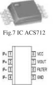
Fig.7 IC
Fig.6 Configuratio Table 1 shows the configurati IC ACS712 and its functions. Table 1 shows the configurati IC ACS712 2.5 V, when current flows fro > 2,5V while when an elec from IP + to IP-, then the ou
ustrial, commercial, and tions example includes sensors n and use of power management, ected power supply, protection
and so forth.
acteristics of the ACS712 current
ith low interference signals
(low- th
agnetic field close to zero
t voltage is corresponding to its
IC ACS712
ation pin IC ACS712
ration of each of each pin on the ns.
ration of each of each pin on the
Function
ich detects the current, there is a ich detects the current, there is a
l terminal
external capacitor which serves dwidth
l output terminal input terminal
graph comparing the voltage the output current.
Fig.7 Charts ACS712 sensor output voltag current
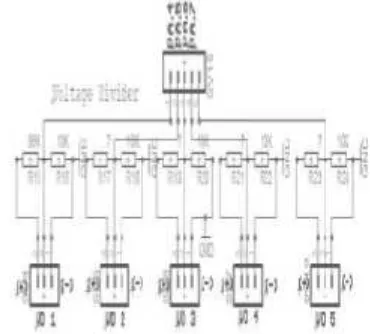
Voltage Divider.Voltage divider circuit is create a reference voltage from a larger so reference voltage point on the sensor, to pr the amplifier circuit or to give a bias component. A voltage divider circuit can with two resistors, an example of a basic voltage divider output of the voltage sourc voltage divider resistors R1 and R2 as shown
Fig.8 Circuit voltage divider The output voltage (Vo) of the v circuit above can be formulated. Current (I) R1 and R2 so that the value of the voltage s addition Vs and Vo can be formulated. VI = Vs + Vo = i · R1 + i · R2
The input voltage is divided into two pa voltage proportional to the value of the resis to voltage. So that the magnitude Vo formula
= =
Figure 10 the voltage divider c voltage divider with a load attached at the current io and voltage drop of vo.
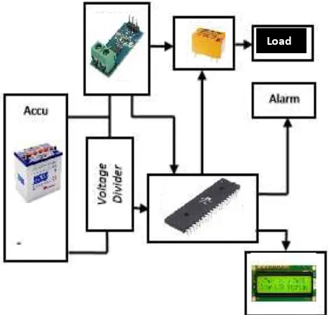
III. RESEARCH METHODS Planning System. Block diagram is one important, because with the block diagram workings of the entire circuit is used. So diagram of the circuit will produce a syste enabled to work in accordance with the desig
Load ut of the electric
ltage to electric
it is usually used to source voltage, a provide a bias to ias to the active n basically made sic circuit with a rce VO VI using wn below.
er
e voltage divider t (I) flowing in the e source VI is the
parts, each rated sistor is subjected ulated as follows.
= =
circuit shows a the output, taking
HODS
one of the most m can be seen the So that the block stem that can be sign.
Fig.10 Block diagram of the Electronic Design. There schematic circuit that will be Regulator circuit. Regulator voltage from batteries into th and 12 VDC. The working prin the power supply, that transformer, rectifier, conden electronic regulation. Accum transformer as an input circu of 48VDC.
Voltage of 48 VDC splicing Accumulator 12V 4 to get the voltage value of working voltage of 48 VDC according to the data sheet, microcontroller 5 VDC.
Fig.11 Power suppl Figure 11 is a schematic circ the output consists of three which is used as a voltage s
Load
= =
the energy in the battery system e are electronic circuit has a be used in solar cell electric car.
tor circuit serves to lower large the low voltage source is 24VDC principle of the circuit as same as t has three important parts: enser as a low pass filter and an umulator in this series is like a ircuit has a large enough voltage
DC and a current of 40 AH of V 40 AH are assembled in series of 48V. BLDC motors with a VDC and a current of 40 AH eet, it can be regulated by the
pply circuit ATMega32
circuit of the power supply with ee DC outputs, namely: 5 VDC e source to the circuit minimum
Proceeding Forum in Research, Science, and Technology (FIRST) 2016 system ATMega32, 12 V as a voltage source relay load,
minimum system and PNP transistor. the BLDC motor as the driving electric cars SOLARCELL, to output 9 V processes that will be used hereinafter, 9VDC as a backup input.
Minimum System Circuit ATMega32
Minimum System ATMega32 circuit has an input voltage of 5 V. Microcontroller can be used to process data per bit or 8 bits simultaneously. Minimum System Usage ATMega32 receives analog voltage signals of ACS712 current sensor and sensor divider.
Flow Sensor Socket circuit ACS712
Fig.12 The series of 5 pieces ACS712 current sensor socket Figure 12 shows a series ACS712 current sensor module socket has three pieces of pin that is + 5V, Signal, and Ground. pin + 5V on this circuit is connected to the power supply of 5V regulator minimum system ATMega32. Pin signal on this circuit is connected to the four ports on the system ADC minimum. Then the second sensor is a voltage sensor, Voltage Divider.
Fig.13 Five Voltage sensor sockets voltage divider Figure.13 Five voltage sensor sockets voltage divider consisting of 2 resistors as a voltage divider which will be measured at the input leg positive (+) and negative (-), an analog voltage signal in the circuit produces a maximum voltage of 5VDC as a data input analog voltage to the to the ADC port on the system minimum ATMega32 result
Voutof the two types of sensors will be processed according to the calculation formula using the program BASCOM AVR and the output of the minimum system are in the form of lcd 16x2 which will display data calculation of energy and generates a signal logic function activates and disconnect relay 12 VDC PNP transistors 30A with the help of a trigger input 557 is 12 VDC.
Fig.14 Transistor circuit
Picture 14 and 16 are integrated functionally as the movement trigger with BLDC Motor with 48VDC/40AH input as the load. The data sent as logic data from ATMega32 microcontroller to the collector and the emitter get 12 VDC voltage and the base given negative voltage as the truth table of transistor PNP BC 557. After transistor work then the relay will receive the logic data and connect the BLCD motor.
Mechanical Design. Charging system in the electric car that functioned to re-charged the accumulator that used when the car work. There are 2 ways in charging an
Accumulator, they’re with solar cell and with 220 AC
Voltage.
The figure below is a mechanical design of electric car charging system.
Fig.15 The charging system IV. RESULT AND DISCUSSION The result of the test can be seen with this table.
Tabel.2 Accu Voltage Measurement 48 / 32Ah using a voltage divider
No.
Measuring Instrument (V)
Accu
Voltage dividerCapacity X (%)
1. 55V 5 1023 100
2. 54V 4.9 1003 100
3. 53V 4.8 983 100
4. 52V 4.7 962 100
5. 51V 4.6 943 50
6. 50V 4.5 921 37
7. 49V 4.4 901 25
8. 48V 4.3 880 12
9. 47V 4.2 860 0
From the Table 2 the measurement of voltage variation in accumulator 48V/Ah. In the voltage divider circuit that used as sensor to measure the voltage in energy management system. Voltage divider produce converted output voltage to microcontroller in the maximum limit 5V with 2 resistor that designed series, charging or there is voltage in the accumulator cell. But, the normal voltage for full condition accumulator is 52V. So 55V voltage divider is used to give the toleration so the converted output voltage is not bigger than 5V so it’s not break the
microcontroller, using the voltage divider formula the resistor value can be adjusted, the first resistor is 100K Ohm and the second resistor is 10K Ohm. So the voltage divider can produce the maximum voltage as big as 5V when detected the maximum voltage as big as 55V that will be continued to the microcontroller in the ADC PORTA2 pin. When the battery in 100% condition show 52 V or 55
V and when it’s in low condition it shows 47V. 55V will be
detected when 4 accumulator assembled in series just charged or surface tension at the battery cells (Charging Surface). However, the normal stress conditions for 52V batteries are full. So for voltage of 55-52 V battery capacity will be read as 100% due to surface charger tension. Range is used to measure the battery capacity is 55 V-47 V = 8V. The difference between a full battery and a weak battery is 8 V. This difference will be divided by 100%, thus
%= 0.8 V. For every increase of 1% then an increase in the voltage of 0.8 V whereas, for the conversion of voltage signal Vout of voltage divider into percentages on the microcontroller is with the following formula:
100% = Vin (ADC)–860 = 1024–860 = 164
=164–64 = 100%
Explanation:
Vin (max) = 55V
Vout (max) = 5V ,
Vout (max)ADC = 1023
Vin (min) = 47V
Vout (min) = 4.2V
Vout (max)ADC = 860
∆Vout (ADC) = Vout(max)–Vout(min) = 5–4.2 = 0.8
Thus,an increase of 0.8 volts at every increase of 1% Table.3 Load currentwith ACS712 30A
Load (A)
N o
Load A ACS712 31A
Vout ADC = Vinx Vout
Conversion (A)
1 0 2.5 512 0
2 1 2.6 548 1
3 2 2.7 585 2
4 3 2.8 573 3
5 4 2.9 593 4
6 5 3.0 614 5
7 6 3.1 634 6
8 7 3.2 655 7
9 8 3.3 675 8
10 9 3.4 696 9
11 10 3.5 712 10
12 11 3.6 737 11
13 12 3.7 757 12
14 13 3.8 778 13
15 14 3.9 798 14
16 15 4.0 819 15
17 16 4.1 839 16
18 17 4.2 860 17
19 18 4.3 880 18
20 19 4.4 901 19
21 20 4.5 921 20
From the results of Table 3 is the data conversion value of the output voltage signal 30A ACS712 current sensor. 30A ACS712 sensors work on the voltage of 5V can generate voltage Voutfrom 2.5 to 0A to 30A and 5V. In the test data ACS712 current sensor 30A is operated only current measurement up to 20A continuous load due to the use of energy management systems across the maximum load on the electric car approximately 20A. From the measurement data of Table 5 ACS712 / 30A changes increase the output voltage signal Voutto the continue load. Namely an increase in the output voltage signal is proportional to the increase in the loads measured.
To view conversion data continuous current, the output voltage Vout at the foot of the ACS712 current sensor connected to the microcontroller pin ADC on PORTA.0 converted into data ADC values, for current 0A to the output voltage is 2.5V Data ADCnya 512. By using the formula:
Continue Current = ∆ .
. Explanation:
Proceeding Forum in Research, Science, and Technology (FIRST) 2016 Accumulator Energy Management Measurement
Table.4 Accu energy consumption on 42.48 minute sample with 30km/h speed
4 19.6 63.72 52.5 Normal
5 19.6 53.10 51.4 16 50
M
6 19.6 42.48 50.3 12 37.5 Alarm
7 19.6 31.86 49.2 8 25 electricity were taken from a sample of using the maximum speed of the electric car of 30 Km / H. From the description of the data at a maximum speed measured continuous load current of 19.6A comprising electronic load and mechanical load. Electronic load such as system monitoring, relay unit, ACS712, optocoupler, seven segment, and bluetooth HC-06 using the maximum current load of 3A and inductive load of the motor plus a maximum of 16.6A. in order to get maximum load current of 19.6A. for the current state of battery voltage just finished di-charging has become 55V voltage charging surface and to a normal state when the batteries full, or when the capacity of 100% at 52.5V voltage at 48V batteries.
Fig.16Battery capacity percentage graph toward the duration (lifetime)
In figure 16 describes the graph about the length of usage time in minutes to the percentage of battery capacity (%). From the graph above it can be seen that the percentage of 100% battery capacity of the car can be run with the
maximum current load or at a speed of 30 Km / H in a time of 95.58 minutes or 1:35 hours.
Of all the measurement data is carried out, an energy management system has an important role in electric cars. Energy management system serves to determine the continuous flow using ACS712 current sensor mounted on the positive output 48 V batteries to be connected to the load on the electric car. ACS712 output has been converted using the ATmega32 minimum system POTRA.1 ADC pin. of energy capacity can be measured using the Voltage divider. Alarm indicator which will sound in order to remind the driver that the energy in the accumulator of an electric car is below 40%. Then the second is the output termination and connection relay automatically load when the battery energy level conditions on the electric car is less than 15%. It aims to provide security to the batteries in order to avoid voltage drop that causes damage to the battery when the car is still running when the batteries in electric cars is almost gone
V. CONCLUSION
Based on the analysis results, we can conclude that: 1. Accumulator conditions on the electric car is 100%
state (High) Indication of Surface Charging, 37,5% -50% status (Middle) and Alarm Indication Normal, and 25% state (Low) Discharge Indicator
2. With the use of batteries 48V 32A that are arranged in series on the electric car can run at a maximum speed for 95.58 minutes. The maximum load current used in electric cars is 19.6 A.
3. The design of the load relay automatic energy management system aims to provide security to the batteries in order to avoid voltage drop that causes damage to the battery when the car is still running when the batteries in electric cars is almost gone
REFERENCES
[1] Azzumar Muhammad, 2012. PermodelandanSimulasi BLDC Motor Kecil untukAplikasiAktuatorSiripRoket. Depok: Universitas Indonesia. [2] Daryanto,2006.PengetahuanBaterai Mobil. BumiAksara [3] Petruzella, Frank D. 2011.ElektronikIndustri. Yogyakarta:Andi [4] Nugraha, Dhani. 2011. Tutorial Mikrokontroler ATMega32