man v
•CoverstheOracleDatabaseAppliancefromarchitecturethroughconfiguration •Providesatechnicalresourceforsystemanddatabaseadministrators •ExaminespracticalusecasesfortheOracleDatabaseAppliance
•AssembletheOracleDatabaseAppliance
•Understandthearchitectureanditsimplicationsfordeployment •Configurenetworkaccessandprotectagainstintrusion •Monitorandtroubleshoottheappliance
For your convenience Apress has placed some of the front
matter material after the index. Please use the Bookmarks
Contents at a Glance
Foreword ...
xiii
About the Authors ...
xv
About the Technical Reviewer ...
xvii
Acknowledgments ...
xix
Introduction ...
xxi
Chapter 1: Oracle Database Appliance
■
...
1
Chapter 2: Integrated Lights Out Management
■
...
13
Chapter 3: Installation
■
...
31
Chapter 4: Database Configuration
■
...
55
Chapter 5: Networking
■
...
81
Chapter 6: Monitoring the Oracle Database Appliance
■
...
99
Chapter 7: Diagnosing the Oracle Database Appliance
■
...
115
Chapter 8: Patching the Oracle Database Appliance
■
...
141
Chapter 9: Business Values for the ODA
■
...
159
Chapter 10: Virtualization and the ODA
■
...
173
Chapter 11: e-Business Suite and the ODA
■
...
189
Chapter 12: Oracle Enterprise Manager and the ODA
■
...
225
Introduction
The world of information technology has changed rapidly since the inception of computers during the ’60s and ’70s. These changes have helped propel many different aspects of our economy to include what and how businesses conduct daily operations. With these changes to organizations, especially internally with information technology, faster and better ways of achieving business goals have been pushed and developed.
As businesses start to depend more on data stored within their systems, faster ways of processing and
reporting data have developed. Over time, organizations have asked for ways to improve processing, achieve greater throughput, and report more quickly. This eventually led to the development of systems that could leverage both software and hardware resources together, leading to the development of engineered systems.
After the development of engineered systems, such as the Exadata, many organizations were left with a difficult choice of either a massive expense for an engineered system (Exadata) or to build their own. This decision affects a large number of small- to medium-sized businesses. Oracle recognized this, leading to the birth of the Oracle Database Appliance.
What Is the Oracle Database Appliance?
At a high level, the Oracle Database Appliance is a server and storage and network hardware, combined with network, cluster, and database software and templates. The Oracle Database Appliance is a fully supported, integrated system consisting of hardware and software components. Being that it is an integrated system, it is engineered to work at both the software and hardware layers, is simple to configure and maintain, and preconfigured to work with database workloads. Additionally, it is designed to help organizations minimize costs, increase adoption time, and lower risk in database deployment and maintenance.
How This Book Came to Be Written
Why Buy This Book
If you are a DBA or a manager who deals with databases on a regular basis, this book is going to provide you with information on using the Oracle Database Appliance. No matter how complex an environment your organization has, you will be able to use the information in this book to bring the Oracle Database Appliance, throughout its life cycle, within your organization.
Oracle Database Appliance
The Oracle Database Appliance (ODA) is a newer member of Oracle’s Engineered Systems family of products. It is meant as an entry-level appliance to provide a pain-free, Oracle Database implementation experience. An ODA implementation saves time and money by providing an easier path to deploying a highly available database solution using a combination of the Oracle Database Enterprise edition and Oracle Unbreakable Linux (OEL) clustered across two nodes.
Why an Appliance?
Traditional hardware deployments can take anywhere from weeks to months to implement, depending on the procurement and the deployment model that a company employs. Upgrades to Oracle database versions can also be a challenge because each hardware/software combination needs certification at various levels to ensure a smooth upgrade.
The evolution of the Oracle Database is very important to understand as we look at the engineered systems. Oracle has incorporated a variety of enhancements as it evolved the Oracle Database product. Through its evolution, the complexity of the software has increased. From a very simplistic relational database management system (RDBMS) in Oracle V4 to the reintroduction of Oracle Real Application Clusters, which was released as part of V9, Oracle has revolutionized the RDBMS and clusterware spectrum.
The database administrator (DBA) role has evolved as a result of the enhancements to the Oracle Database product line. Roles and responsibilities have increased, and coordination with multiple infrastructure groups that have a disparate goal has also increased. As Oracle introduced versions 10 and 11 of the database, the life of a DBA became more complicated, particularly with the addition of Automatic Storage Management (ASM) and Grid Infrastructure (GI). The DBA is now in charge of volume management and for ensuring that all aspects of the infrastructure meet the requirements of the Oracle stack.
Complexity has its own perils, and problem resolution time is greatly increased as the number of components increase. Virtualization of hardware and platform can also make things worse if all aspects of infrastructure are not fully evaluated properly. The infrastructure and software costs to ensure complete compliance can be very expensive for an organization, and innocently updating firmware in one piece of the infrastructure can cause turmoil in other aspects of the infrastructure or software.
The human element is very important as we talk about the advances in infrastructure and software. DBAs have seen their responsibilities increase with each release of the Oracle database stack. They are now expected to understand all aspects of the RDBMS, infrastructure, OS, and network to deliver a comprehensive and defect-free solution to the customer. Delivery of such a solution requires extensive coordination with various infrastructure groups, and may require costly upgrades or purchases.
Management costs and build costs are significantly reduced because the ODA comes preconfigured with interconnect and storage, as well as a tuned OS. The ODA also includes the option to virtualize the appliance, which can result in significant savings to the organization by providing a complete boxed solution for virtualizing applications and the database.
Businesses and enterprises often struggle with deadlines, and by using a traditional model of deployment, which includes procurement as part of the project budget, it is often very hard to provide the agility that is required for a business to bring ideas to fruition quickly. A typical deployment cycle can range from 30 to 90 days, which can make a product that requires a database harder to get to market. Figure 1-1 shows a typical deployment cycle in a traditional system vs. that with an ODA, based on deployment experience with Oracle Real Application Clusters (RAC). This may vary by the deployment maturity model of an organization.
Traditional Setup
Figure 1-1. Traditional server vs. ODA with RAC
The disparity between a traditional setup and the setup of an ODA is huge. It may differ based upon the practices and processes implemented by an organization. Traditionally, the process to deploy hardware includes the following steps:
1. Procurement of hardware
2. Delivery of hardware
3. Setup of hardware
4. Network connectivity and switch setup
5. OS setup and tuning
6. Database software setup
7. Best practices post setup
The ODA’s unique licensing model, as well as the ability to provide virtualization out of the box, can help organizations build a scalable model for deploying applications and databases at a fraction of the time and cost. The ODA comes as a complete package, which makes Oracle responsible for all components. This allows the organization to focus on the business rather than the technology, and frees up the DBA’s time to focus on design rather than setup and coordination. A traditional ODA deployment exercise consists of the following:
1. Procure hardware
2. Install hardware
3. Set up the database appliance
4. Implement organizational best practices
The steps needed to implement an ODA are significantly less than a traditional setup because Oracle bundles hardware and software as one unit and allows for management and maintenance of the stack as one, which is not how traditional infrastructure is managed.
The Appliance Hardware
ODA is marketed using the tagline “Simple, Reliable, Affordable.” Currently, it is available in two hardware
configurations: the original and the ODA X3-2. Billed as part of Oracle’s strategy for “Hardware, Software, Complete,” the ODA brings forward a simple cluster that includes two database server nodes, storage, as well as cluster
interconnect and simplified management built into the appliance itself.
Oracle Database Appliance V1
To date, Oracle has shipped more than 1,000 Oracle Database Appliances.1 The original ODA is a complete unified box
solution that contains two 2U Sun M4370 servers, along with storage and networking components. The total size of the ODA V1 is 4U in datacenter rack terms. Figures 1-2 and 1-3 show the front and back of the appliance, respectively, and highlight the simplicity of the ODA’s design.
Each ODA unit consists of two physical servers, and each physical server consists of a server node and an Integrated Lights Out Management (ILOM) component. Chapter 2 delves into detail about the ILOM and explains the importance of the ILOM in the ODA unit. Table 1-1 lists the specifications of the ODA V1 from the Oracle Database Appliance Datasheet. (My Oracle Support Note 1385831.1 provides the same information.)
Figure 1-3. The back of the Oracle Database Appliance V1
Table 1-1. Oracle Database Appliance V1 Specs
Component
Specification
CPU 2x 6-core Intel Xeon X5675 3.07GHz
Memory 96GB RAM (12 x DDR3-1333 8GB DIMMs)
Network 2x 10GbE (SFP+) PCIe card 6x 1GbE PCIe card
2x 1GbE (Intel 82571) onboard integrated redundant cluster interconnect
Internal Storage 2x 500GB SATA - for operating system 1x 4GB USB internal
RAID Controller 2x LSI SAS9211-8i SAS HBA
Shared Storage 20x 600GB - 3.5" SAS 15k RPM HDD (Seagate Cheetah) - for RDBMS DATA (any slot except the top row of disks)
4x 73GB - 3.5" SAS2 SSDs - for RDBMS REDO (slot in the top row of four disks) SSD from STEC (ZeusIOPS - multilevel cell (MLC) version with SAS interface)
Operating System Oracle Enterprise Linux 5.5 (on ODA software version 2.1), 5.8 (on ODA software version 2.2) x86_64
The ODA comes with a very powerful Intel Xeon processor, as well as enough memory and storage to accommodate a variety of Online Transaction Processing( OLTP) and some smaller data warehouse workloads. The network interconnect is built into the appliance, which removes the need for a switch for the interconnect for communication between the nodes. In terms of storage, depending on the ODA software version and redundancy layer, you can have between 4 and 6 terabytes (TB) of space.
controllers, which are connected to an onboard SAS expander. Each SAS expander, in turn, is connected to 12 of the hard disks in the ODA. Oracle uses Linux multipathing to avoid disk-path failures. Solid-state drives (SSD) have been added for redo to overcome rotating disk latency, because the controller of the rotating disk has no cache. Disk sizing on the ODA depends on many factors, including the version of the ODA software that is running on the appliance. Table 1-2 shows the various disk configurations and configuration options that are supported on the ODA.
Table 1-2. ODA Disk Configurations
Configuration
Option
Disk Group
Type/Redundancy
Backup Type
Space Available (GB)
Software Version
Supported
1 DATA HIGH External 3200 All versions
1 RECO HIGH External 488 All versions
1 REDO HIGH None 91 All versions
2 DATA HIGH Local 1600 All versions
2 RECO HIGH Local 2088 All versions
2 REDO HIGH None 91 All versions
3 DATA NORMAL External 4800 2.4 and above
3 RECO NORMAL External 733 2.4 and above
3 REDO HIGH External 91 2.4 and above
4 DATA NORMAL Local 2400 2.4 and above
4 RECO NORMAL Local 3133 2.4 and above
4 REDO NORMAL None 91 2.4 and above
Table 1-2 illustrates various disk configuration options supported by the ODA. As you can see, the space has approximately 4TB usable due to all disk groups being triple-mirrored (high redundancy) in configuration options 1 and 2. Depending on which configuration you chose, you will have more space in DATA or RECO disk groups.
Oracle Database Appliance 2.4 introduced the option to allow mirrored (normal redundancy) disk groups for DATA and RECO. This is highlighted in Table 1-2 as configuration options 3 and 4. This was done primarily to allow customers the choice of space based on the environment that the ODA is being deployed. Typically, the recommendation is to deploy mirroring (normal redundancy) on development/test systems.
The ODA runs Oracle Enterprise Linux OS with support only for the Unbreakable Enterprise Kernel (UEK) as of software version 2.2. The following is a snapshot of ODA software version 2.6:
Linux oda01 2.6.32-300.32.5.el5uek #1 SMP Wed Oct 31 22:06:21 PDT 2012 x86_64 x86_64 x86_64 GNU/Linux Enterprise Linux Enterprise Linux Server release 5.8 (Carthage)
Figure 1-4. Oracle Database Appliance V1 callouts
Table 1-3. Oracle Database Appliance Connector Descriptions2
Callout
Label
Ethernet
Bond
Description
1 Power connectors.
2 PCIe 1 Eth 7, 6, 5, 4
(left to right)
bond1, bond2
Eth 4 and Eth 5 are configured as bond1. Eth 6 and Eth 7 are configured as bond 2. These ports are used for custom configurations or for separate backup, disaster recovery, and network management.
3 PCIe 0 Eth 8, Eth 9 xbond0 Two 10 GbE ports. In 10 GbE systems, these are connected to the public network.
4 SerMgt Serial connector to Oracle ILOM and system console.
5 Net 0, Net 1 Eth2, Eth3 bond0 Two 1 GbE connectors. In 1 GbE systems, these are connected to the public network.
6 NetMgt Ethernet connection for Oracle ILOM.
7 USB and Video Used for connecting to system console.
8 Server Node 0.
9 Server Node 1.
The ODA setup poster is a simple and easy-to-understand method for installing and setting up the appliance. The poster is a step-by-step guide that explains connecting the cables to deploy the software, which results in a fully functional clustered database server. Figure 1-5 shows this in detail. Oracle updates the poster with every release. The poster is available in the documentation web site for ODA at http://docs.oracle.com/cd/E22693_01.
The ODA comes with fully redundant hardware and includes two 10 gigabit Ethernet (GbE) interfaces that are bonded together via the Linux operating system to provide redundancy, as well as two 3×2, 1GbE interfaces that are also bonded together for purposes of redundancy. There is a connector for the ILOM, as well as USB and VGA for keyboard and external monitor connections, if needed.
The ODA is unique in the sense that it has an onboard interconnect that is used to connect the two database servers. The interconnect is 1GbE and uses an Intel 82571 board; it is not bonded. That is why there are two cluster interconnects leading to two HAIP devices seen from the clusterware. Since the private interconnects are internal to the appliance, no external cabling is required for them.
The ODA is managed by Oracle Appliance Kit (OAK), which is a proprietary piece of software that is specific to the ODA. The OAK and various ODA software features are discussed in subsequent chapters. Virtualization is added to the ODA platform as an option, and it is also discussed in subsequent chapters.
Oracle Database Appliance X3-2
The ODA X3-2 is the second generation of the ODA devices. It has a lot of new features, as well as more capacity than its predecessor. Figure 1-6 shows the appliance from the front.
Figure 1-6. Oracle Database Appliance X3-2
Table 1-4. Oracle Database Appliance X3-2 Specs
Component
Specification
CPU Two 8-core Intel® Xeon® processors E5-2690
Memory 256GB (sixteen 16GB RDIMMs at 1600 MHz)
Network Four 100/1000/10G Base-T Ethernet ports (onboard)
1x dual-port 10GBase-T interconnect for cluster communication
Internal Storage Two 2.5-inch 600GB 10K rpm SAS-2 HDDs (mirrored) OS
RAID Controller 1x dual-port internal SAS-2 HBA 2x dual-port external SAS-2 HBA
Shared Storage Twenty 2.5-inch 900GB 10K rpm SAS-2 HDDs
Four 2.5-inch 200GB SAS-2 SLC SSDs per shelf for database redo logs
Optional storage expansion with additional storage shelf doubles storage capacity External NFS storage support
Operating System Oracle Enterprise Linux 5.8 x86_64
The Oracle Database Appliance X3-2 expands the capabilities found in the ODA V1 and packs a punch in terms of hardware and storage capabilities. Oracle has taken a slightly different approach in terms of hardware architecture for the X3-2. The server nodes and the storage rack are now two separate units that are connected together, and there is an option to add an expansion storage rack to double the storage capacity of the appliance.
The X3-2 is more modular in structure than the version 1 appliance and it provides flexibility. Customers are able to expand storage by adding an additional storage rack. They can create a storage rack and a server node rack in their datacenters; however, we recommend installing the components together.
ODA X3-2 provides a packed spec sheet. It is a powerful successor to the original ODA. Oracle has added a little more complexity in the install, which accommodates the flexibility of having a storage shelf that is separate from the actual server units. This allows for adding a second shelf as needed, but you will now need to ensure that the cabling is done appropriately per the setup poster that is provided with the appliance.
As with the original ODA, the setup poster for the X3-2 is enhanced to be a handy resource to help with the installation. Figure 1-7 shows the poster, which is updated with each version of the software. Currently, the setup poster has instructions on setting up the ODA as a bare metal or a virtualized environment.
Figure 1-7. Oracle Database Appliance X3-2 setup poster
If you look at a poster, you’ll see that it suggests a deviation from the original design, in which there is a connection and cables that need to run between the server nodes, as well as from the server nodes to the storage shelf, and optionally to an additional storage shelf as well. Figure 1-8 shows what the server node looks like. Table 1-5
Table 1-5. Callouts for the ODA Server Node Rear
Callout
Legend
Callout
Legend
1 Power Supply (PS) 0 with fan module. 9 NetMgt port. 10/100BASE-T port used to connect to Oracle Integrated Lights Out Manager (Oracle ILOM) SP.
2 Power Supply (PS) 0 status indicators: Service Required LED: amber, AC OK LED: green.
10 Serial management
(SerMgt)/RJ-45 serial port.
3 Power Supply (PS) 1 with fan module. 11 Network (NET) 100/1000/10000 Mbps Base-T EthernetRJ-45 connector: NET 3.
4 Power Supply (PS) 1 status indicators: Service Required LED: amber, AC OK LED: green.
12 Network (NET) 100/1000/10000 Mbps Base-T Ethernet port with
RJ-45 connector: NET 2.
5 System status indicators: Locator LED: white, Service Required LED: amber, Power/OK LED: green.
13 Network (NET) 1100/1000/10000 Mbps Base-T Ethernet port with
RJ-45 connector: NET 1.
6 PCIe card slot 1. Provides two 10GBase-T Ethernet with RJ-45 connector ports for private interconnect between server nodes.
14 Network (NET) 100/1000/10000 Mbps Base-T Ethernet port with
RJ-45 connector: NET 0.
7 PCIe card slot 2. Provides two SAS-2 connectors used to connect servers to the storage shelf and storage expansion shelf.
15 USB 2.0 connectors (2).
8 PCIe card slot 3. Provides two SAS-2
connectors used to connect the servers to the storage shelf and the storage expansion shelf.
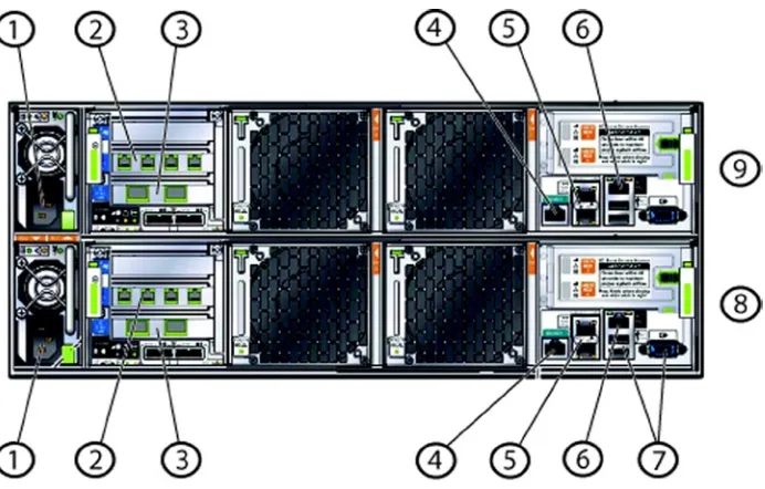
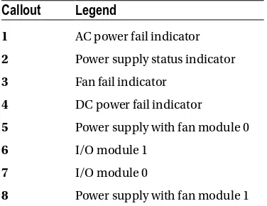
The storage shelf is an independent component. You can see the structure and components that are part of the storage shelf in Figure 1-9. Table 1-6 describes the various callouts.
Figure 1-9. Oracle Database Appliance X3-2 storage shelf
Table 1-6. Oracle Database Appliance Storage Shelf Callouts
Callout
Legend
1 AC power fail indicator
2 Power supply status indicator
3 Fan fail indicator
4 DC power fail indicator
5 Power supply with fan module 0
6 I/O module 1
7 I/O module 0
Due to the addition of the storage shelf and large-sized drives, Oracle Database Appliance X3-2 provides a lot more storage space than its predecessor. And its workload capability has been expanded significantly to accommodate various data mart–style workloads.
ODA X3-2 supports the same four disk configurations shown earlier in Table 1-2, but the sizing is different. Table 1-7
outlines the sizing options available on the X3-2 platform.
Summary
This chapter looked at the Oracle Database Appliance (ODA)—both the original and the X3-2 models. Originally, the ODA was geared toward small- and medium-sized businesses, but it has gained popularity in the enterprise sector as well. The all-in-one, all-encompassing architecture that allows for capacity on demand are the features that have drawn praise. Simplicity of deployment and management allow for cost savings over traditional infrastructure deployment models. An ODA provides high availability and redundancy out of the box, and applies Oracle’s best practices to the system.
Table 1-7. ODA X3-2 Disk Configurations
Configuration
Option
Disk Group
Type/Redundancy
Backup Type
Space
Available (GB)
W/Expansion
Shelf (GB)
1 DATA HIGH External 4800 9600
1 RECO HIGH External 733 1466
1 REDO HIGH None 248 496
2 DATA HIGH Local 2400 4800
2 RECO HIGH Local 3133 6266
2 REDO HIGH None 248 496
3 DATA NORMAL External 7200 14400
3 RECO NORMAL External 1100 2200
3 REDO HIGH External 248 496
4 DATA NORMAL Local 3600 7200
4 RECO NORMAL Local 4700 9400
Integrated Lights Out Management
The Oracle Database Appliance (ODA) is a bundle of two server nodes that include storage and embedded cluster networking. Each server node has an Integrated Lights Out Manager (ILOM) interface that is used for management and maintenance tasks. This chapter will dive into what an ILOM is and how to use it in the context of the Database Appliance.
Introduction to ILOM
An ILOM is a service processor (SP) that is embedded into all Oracle Sun Server–based products. The aim of an ILOM is to provide support for a server in a manner such that access to the datacenter is not required for day-to-day support functions. An ILOM also provides access to a variety of diagnostic features and has integration with Oracle’s Automatic Service Request (ASR) to provide call-home functionality to report hardware failures to Oracle for fast support.
The Oracle ILOM service processors provide a wide array of features, and its functional aspects improve with every release of the ILOM. The ODA V1 and X3-2 come with different ILOM versions, due to the enhancements in the service processor itself, but at its core, the ILOM allows for the following:
Remote KVMS capabilities
Integration with a variety of authentication systems, such as LDAP (Lightweight Directory
•
Access Protocol ), SSL (Secure Sockets Layer), Radius, and Active Directory
Remote syslog setup
Access to various part and serial numbers
•
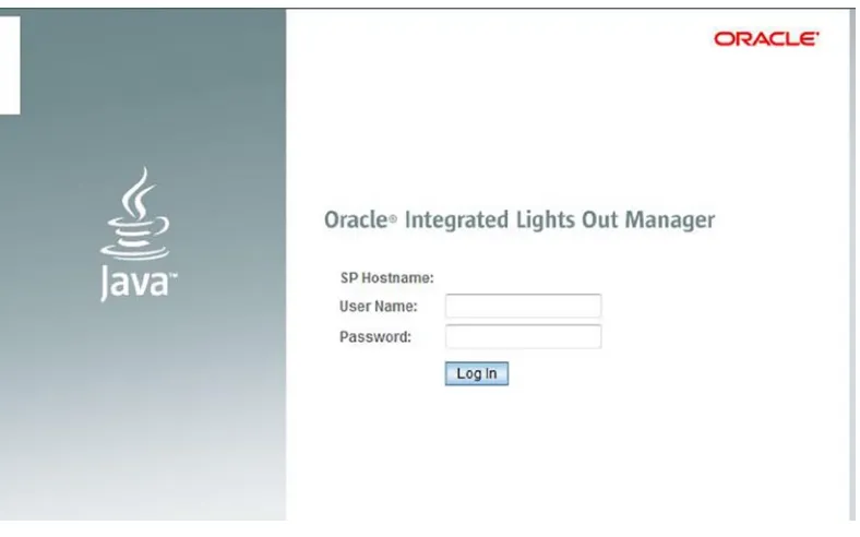
Figure 2-1 shows the starting screen that you see when you log in to an ILOM via your browser. The screen has three main components. The layout is a bit different from the ODA V1 layout in terms of design, but most common functionalities have stayed the same.
Figure 2-1. The ILOM running on an ODA X3-2 Sun Fire X4170 M3
The General Information section is the primary place to look at for basic system information per server node in a visually pleasing manner. Information you’ll find there includes:
System type
•
Model
•
Part number
•
Component model
•
ILOM and system MAC address
•
Primary operating system
•
The Actions section is the place that provides easy access to various commonly used functions that an ILOM user will need to access. These include updating the firmware, powering the server on or off, and recycling the service processor by toggling various options of the power state. You can also turn on the locator beacon so that the system can be located in the datacenter (new to X3-2), and you can use the remote console to access the server nodes.
The Status section provides a real-time status on the physical state of components that are contained within a server node. The Status section looks at the following:
Processors
•
Memory
•
Power
•
Cooling
•
Storage
•
Networking
The Summary screen shown in Figure 2-1 is rich in information and allows you to get a lot of information summarized quickly. The menu section on the left allows getting more detailed information on each of the components. The menu also includes options for setup and customization of the ILOM
Figure 2-2 shows the summary screen from the original Database Appliance. As you can see, the new interface in Figure 2-1 provides a much easier way to find information, and the menu navigation is much more intuitive. As we go through the features in the sections to follow, we will point how to get to various locations from both ILOMs.
ILOM Features
The ILOM is capable of providing a vast array of services. Looking at the ILOM and all its features are beyond the scope of this book, but we will look at a few of the important features that are needed from the perspective of managing an ODA.
Remote KVMS Service
The Remote KVMS (Keyboard, Video, Mouse ,Storage is a very important part of the ILOM and is probably what you will use based on your familiarity and experience with remote access to the appliance. The Remote KVMS service allows you to remotely control a server node from a browser. The Remote KVMS uses Virtual Network Computing (VNC) to access the server nodes. Thus you should be sure to open the firewall ports shown in Table 2-1 on your workstation.
The setup of an ILOM is covered later in the chapter, but once an ILOM is setup, the Remote KVMS allows access to the server console. Remote KVMS also allows remote installation, which is needed to do a bare-metal server installation. Access to the remote control feature is a bit different between V1 and X3-2 of the ODA, but both offer the same in terms of functionality.
Figure 2-3 shows a cutout of the location of the remote control features in ODA V1 vs. ODA X3-2. The remote control feature is much more easily accessible on the ODA X3-2 via the main screen. By contrast, it takes a couple of clicks to get to the remote control feature on the ODA V1.
Table 2-1. Firewall Ports Needed for RKVMS Access
Ports
Service
Type
443 TCP HTTPS (inbound)
5120 TCP Remote CD (outbound)
5121 TCP Remote keyboard and mouse
5123 TCP Remote Floppy
6577 TCP CURI (API) - TCP and SSL
7578 TCP Video Data (bi-directional)
161 UDP SNMP V3 Access (inbound)
3072 UDP Trap Out (outbound only)
The remote console is an easy way to get access to the server console, to configure a server, or to diagnose issues, if remote connectivity to the server itself is not available. Once the remote console is launched, you see a login prompt similar to what you see when you log in to a Unix machine. This allows you to log in to the server from the console.
The remote console provides access to the console messages and allows users to log in to the system. Each server node (SN) has its own ILOM, so in the context of an ODA, there are two ILOMs. This is very important because each physical server in the ODA has its own ILOM that has to be used for managing and maintaining that physical server.
Integrated Shell
The ILOM is also accessible via a shell that is integrated into the service processor. That shell is a convenient way to access and operate an ILOM. The ILOM shell can be accessed via various methods, as follows:
The NET MGT port on the server node (serial connection)
•
The server node using ipmitool over TCP
•
TCP to SSH (Secure Shell) directly into the ILOM
•
IPMITool over LAN, locally or from any device that supports ipmitool
•
The integrated shell is used to configure the ILOM for the first time. It can be used by the datacenter team to prepare the ODA for configuration. The integrated shell is also used to perform basic functions like ILOM password changes, checking for system faults, gaining access to the console, and so forth.
The integrated shell is accessible via the ipmitool command. It can also be accessed on the server nodes and remotely using ipmitool with the lanplus protocol. The ipmitool can be accessed via the host for which the SP manages the hardware (as root; the IPMI device in Linux only allows root access). For example:
# ipmitool sunoem cli Connected. Use ^D to exit.
Another way to connect to the SP is via the lanplus protocol. This approach can be used on a remote machine where ipmitool is installed. Here’s an example:
[root@mxt101 ~]# ipmitool -I lanplus -H <ilom hostname/address> -U <ilom username> -P <ilom user's password> sunoem cli
Connected. Use ^D to exit. ->
The ILOM can be accessed remotely via native SSH as well. Here’s how that is done:
$ ssh <ilom username>@<ilom hostname/address> Password:
Oracle(R) Integrated Lights Out Manager
Version 3.0.16.10.d r74499
Copyright (c) 2012, Oracle and/or its affiliates. All rights reserved.
In order to access and execute these commands remotely, it is very important to ensure that that the ILOM integrated shell is accessible and available. We discussed the ports needed for Remote KVMS in Table 2-1. You should also consider the ports listed in Table 2-3. Ports are based on standard Oracle defaults and can be configured based on requirements.
Table 2-2. Common ILOM CLI Commands
ILOM CLI Command
Description
show /SYS power_state fault_state Shows the power_state (On or Off ) for the host, and the fault state. OK means nothing faulted. If the ILOM/SP detects failure, the fault state will not be OK.
stop /SYS Stops the host in a graceful way. If the host doesn’t respond or doesn’t go down, you can force the host to stop by adding -f. For example:
stop -f /SYS
start /SYS Starts a host.
show faulty Lists all detected failures, if any.
start /SP/console Starts text-based console access.
set /SP/users/root password=welcome1 Sets a new password for the ILOM.
set /SP/network
reset /SP Resets the SP, which means the host as well as the SP will be rebooted.
Show /SP/version Displays the current SP version.
Table 2-3. Ports Used for ILOM Access
Port
Type
Description
22 SSH over TCP SSH - Secure Shell (inbound)
69 TFTP over UDP TFTP (outbound)
80 HTTP over TCP Web (user-configurable; inbound)
123 NTP over UDP NTP - Network Time Protocol (outbound)
161 SNMP over UDP SNMP - (user-configurable; inbound)
162 IPMI over UDP IPMI - Platform Event Trap (PET) (outbound)
389 LDAP over UDP/TCP LDAP (user-configurable; outbound)
443 HTTPS over TCP (user-configurable; inbound)
514 Syslog over UDP Syslog - (outbound)
623 IPMI over UDP IPMI (bidirectional)
546 DHCP over UDP DHCP (bidirectonal)
Security Management
The ILOM allows account management and integration with a variety of popular authentication protocols. Discussing them all in detail would be out of the scope of this book. We will look at Active Directory integration as part of this section and also discuss how to manage users locally.
Local Account Management
The ILOM provides a secure way to authenticate and perform day-to-day functions via locally authenticated accounts. This is the default authentication method to get access to an ILOM. ILOM Account management allows an administrator to provision accounts for a variety of functions. Table 2-4 lists all the roles that are available to users.
Table 2-4. Roles Available for ILOM Authentication
Role
Description
a (Admin) Complete admin privileges
u (User) Provides access to allow creation and deletion of users and to configure authentication services
c (Console) Access to console functions that allow for BIOS updates
r (Reset) Allow for control of the host power, as well as power cycle the SP
o (Read Only) Allows for read-only access to logs and environmental information
Based on the role selected (Administrator, Operator, Advanced Roles), various privileges are given to the user. Users can be created via the ILOM GUI or via the command line.
The following is an example of a command to create a new user named rick:
create /SP/users/rick password=my_secret role=administrator
Having created the user, you can modify the user’s role as follows:
set /SP/users/rick role=operator
You can also delete the user:
delete /SP/users/rick
It is very important to understand the roles and privileges available, and to assign them appropriately to secure your environment. Also take care to change the default ILOM root password immediately after deployment.
Alerting and Syslog Setup
Logging is a very important way of understanding and debugging issues. The Oracle ILOM provides various ways of disseminating logging information. Syslog is disabled by default, but it is the preferred way to centralize logging. SNMP traps can also be set to allow for alerting to remote systems.
Syslog is an ILOM service that needs to be enabled and configured. The process to enable syslog on the ILOM is to add the IP address of the syslog server. Figure 2-5 and Figure 2-6 show the syslog configuration screen that is available in ODA V1 and ODA X3-2, respectively. That screen can be used to configure the ILOM to send data to an external syslog server.
Figure 2-5. ODA V1 syslog setup
Setting up logging to the syslog server is similar for both versions, via command line. Just execute the following command:
set /SP|CMM/clients/syslog destination_ip=syslog_server_
SNMP alerts can also be set up in a similar fashion. The SNMP service is enabled by default and is configured dependent on the target SNMP trap receiving system. The ILOM supports SNMP protocols v1, v2c, and v3. SNMP protocols v1 and v2c use communities as the authentication method. A default read-only community named public
and a read/write community named private are pre-created on the ILOM. A customized string can be used to send SNMP traps, if needed, depending on the environmental setup. SNMP protocol v3 requires username/password–based authentication.
SNMP is set up in a similar fashion in both ODA V1 and X3-2. On X3-2, the settings are accessible under the following menu option: ILOM Administration ➤ Management Access ➤ SNMP. On V1, go to Configuration Management ➤ System Management Access ➤ SNMP. Figure 2-7 shows the settings screen that you are taken to.
So far, we’ve looked at various ILOM features and setup tasks. The ILOM also provides a wealth of logging information that can be tapped for a variety of purposes. Table 2-5 describes the types of logs that the ILOM provides.
Oracle Database Appliance and the ILOM
The Oracle ILOM is a fully integrated service processor providing complete monitoring and remote access capabilities. It is very important to understand the ILOM and the important role it plays in the context of the ODA.
Oracle Database Appliance Setup via Serial Connection
When the ODA is first setup in the rack at the datacenter, there are steps that need to be followed to allow access to the ODA. These steps are outlined in the Setup Poster.1 After the cabling, the first step is to provide both ODA server nodes
with an IP address. This can be done by either accessing the ODA in the datacenter via a serial cable, or by using a KVM (keyboard, video, mouse) device like Avocent to remotely access the serial port of the device.
The ODA ILOM can be accessed via a serial management (SER MGT) port. MOS Note ID 1395445.1 explains the process of connecting to the ODA to configure the ILOM. The process requires direct physical access to the serial port, which means that this process needs to be executed in the same physical place at which the ODA is located.
Each ODA ships with an RJ-45 serial convertor like the one pictured in Figure 2-8.
Table 2-5. ILOM Logging
Log Type
Description
Syslog Syslog produces output that can be used by logging services like Manage Engine, Splunk and syslogd to name a few. These services run on remote systems. They aggregate logs to provide a unified view for all the events that happen across multiple ILOMs.
Event An ILOM event tracks various types of messages that are generated. These can be messages about errors and warnings, or they can be informational items. Event logs also track the addition and removal of components along with the status of various components that the ILOM Is responsible for.
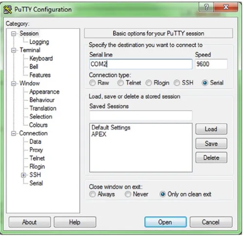
Using an RJ-45 cable, you can connect the cable to the serial port on your laptop or datacenter terminal cart, and connect to access the ILOM using a terminal emulator such as PuTTY or ITerm2. If you lack a serial port, then you can buy one of the many USB-to-serial converter cables that are on the market. Once the connection cable is connected to the laptop and the ODA serial port (and assuming that you are using Windows), check the device manager to see which COM port the USB device is connected to. Then specify that COM port in your PuTTY connection, as shown in Figure 2-9. (If running Linux, then see MOS Note ID 1395445.1 for instructions). Once the port is determined, you can open a terminal and connect to the ODA over the serial line.
Once the connection is made, you will see a login prompt to the ILOM. You need to use the root account and the default root password (changeme) to connect to the ILOM.
An initial configuration of the ILOM should have no IP configuration. You can validate that this is the case by issuing the following command:
# show /SP/network
The Oracle Appliance Kit deployment can set IP networking details of the ILOM, but it is always faster to configure the ILOM IP addresses using the method we describe next. It allows a faster deployment by using the ILOM to deploy the ODA. You need the following information to be able to set the IP configuration for the ILOM for both ODA servers:
Public IP address
•
Netmask
•
Gateway address
•
Depending on your requirements, a static IP or a dynamic IP (DHCP) address can be assigned to the ILOM. The following is an example of assigning a static IP address:
# set /SP/network pendingipdiscovery=static pendingipaddress=1.2.2.65 pendingipnetmask=255.255.255.0 pendingipgateway=1.2.2.254 commitpending=true
The screen shown in Figure 2-10 is the ILOM console; seeing it confirms the successful configuration of the ILOM. Now that the ILOM is successfully configured, you can move on to configure the ODA database nodes.
The ILOM is always turned on as soon as the Database Appliance is cabled and powered on, but the server nodes need to be manually powered on. Execute the following command from an ILOM-integrated shell session to power on a server node. Be sure to execute the command for both nodes.
# start /SYS
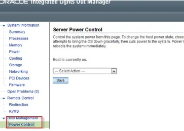
The server node can also be powered on via the ILOM GUI accessible through a browser. ODA V1 and ODA X3-2 have slightly different screens from which to perform various server power–related activities. Figure 2-11 and Figure 2-12 show the screens for V1 and X3-2, respectively.
Bare-Metal Oracle Database Appliance
The Oracle Database Appliance comes preinstalled with base software, but there are circumstances when the ODA servers have to be reimaged. The need to reimage could be due to corruption, or to get the software to the latest version in a fast manner.
The procedure requires downloading the ISO image for the software that needs to be imaged onto the Database Appliance. The latest ISO image is available by following the instructions in MOS Note 888888.1. Download the ISO and unzip it on a laptop or desktop. Go to the Remote Control ➤ Redirection menu, and select Launch Remote Console. Doing so will open the screen that provides console messages and access to the server node. Perform this process on both server nodes.
Once the remote console screen is available, click the Devices menu and select CD ROM Image. You will get a dialog asking you to locate the ISO image.
Once the ISO image has been selected, ensure that the ISO image is mounted. Messages will be displayed on screen to confirm mount of the image. A message indicating a virtual CD-ROM image has been attached will be displayed on screen.
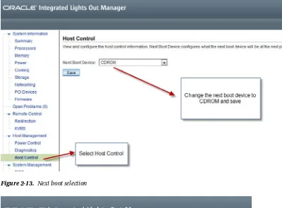
Go to the ILOM. Select the next boot device as CDROM, as shown in Figure 2-13. Then cycle the server node’s power, as shown in Figure 2-14.
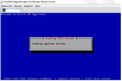
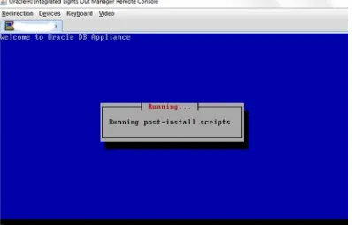
After the power cycle, the redirection screen will show console messages while the system reboots. After the messages, the bare-metal imaging process will begin. Figure 2-15 shows the start of that process.
Figure 2-15. Start of Oracle Database Appliance imaging
The complete imaging process can take from one to two hours, and can be run in parallel on both server nodes to speed up access to the appliance. It is very important to keep in mind that a reimage is a very destructive process that will wipe out all information on an appliance. It is important to back up any information that you have stored in the ODA prior to the image.
Summary
The ILOM is a service processor that is embedded into the ODA. It is the brain of the hardware. The ILOM provides many capabilities from the management and the monitoring perspective. Remote KVMS or shell access allows access to the server nodes remotely to perform “like you are there” functions.
The ILOM can be accessed via a GUI using a modern browser running Java, and also via an integrated shell. Both methods can be used to perform setup and management, as well as to monitor tasks. The ILOM can be
integrated with most common authentication mechanisms, like LDAP and Active Directory. The ILOM also provides a comprehensive logging mechanism and allows logging data to be replicated via remote syslog servers or SNMP traps.
The ILOM provides the functionality to set up the Database Appliance via serial access, as well as provide server power control features. When needed, the ILOM is the console to allow reimaging of the appliance server nodes via CD-ROM images that are available from the Oracle Support web site.
Installation
You already covered the basic tasks to perform a bare-metal restore on the Oracle Database Appliance. Now you need to prepare the Oracle Database Appliance for installation of a Real Application Cluster (RAC) database. With the automation built into the Oracle Database Appliance, this is a straightforward task and can be completed within a few hours. Before starting, you need to finalize some of the prerequisites.
Network and Power Connections
The ODA comes preconfigured for high-availability network access for the primary and secondary networks. These network bonds are preconfigured in the installation image, making installation quick and simple. There are two versions of the Oracle Database Appliance: the original model and the X3-2. They are slightly different from a network aspect. The original Oracle Database Appliance had 12 1000BASE-T Ethernet ports, and the availability of 10G Ethernet using four SPF fiber connections. The X3-2 model simply comes with 8 10GBaseT ports, supporting connection speeds up to 10GBit.
Original ODA
Figure 3-1. Network and other connections on the back of the original ODA
Table 3-1. Descriptions of the Connections Highlighted in Figure 3-1
Callout
Description
1 C13 Power Connectors, shared power bus for both nodes
2 eth4, eth5, eth6, and eth7 from right to left for Node 0; eth4 and eth5 are bond1 and eth6 and eth7 are bond2
3 10BaseT SFP ports for eth8 and eth9 for Node 0, configured as xbond0
4 ILOM Serial Port for Node 0
5 eth2 and eth3, bond0 for public network access
6 ILOM 10/100 BaseT port
7 USB and VGA ports
8 Node 0
ODA X3-2
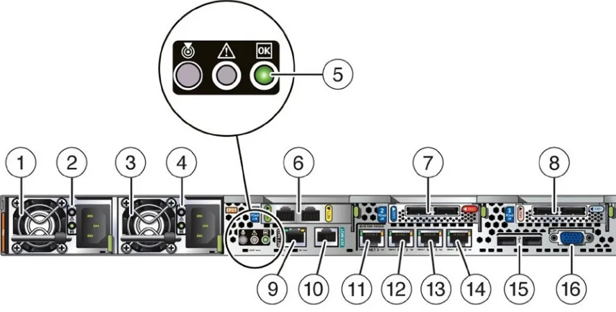
The second-generation Oracle Database Appliance uses two X3 servers for the compute nodes. Each of these servers has two sets of bonded Ethernet ports. By default, bond0 is used for public traffic, and bond1 is used for auxiliary access, which is covered in detail in Chapter 6. Prior to installing the Oracle Database Appliance, connect two cables to the eth2 and eth3 ports. Typically, these will be connected into separate switches in the datacenter for fault tolerance. The default configuration of the bond will load balance traffic between the two ports, automatically recovering from a single network path failure. Figure 3-2 and Table 3-2 illustrate and provide details on the connections on the rear of an X3-2 Oracle Database Appliance.
Figure 3-2. Network and other connections on the back of the X3-2 ODA
Table 3-2. Descriptions of the Connections Highlighted in Figure 3-2
Callout
Description
1 Power Supply 0 Fan
2 Power Supply 0
3 Power Supply 1 Fan
4 Power Supply 1
5 System indicator and locator lights
6 Cluster Interconnect, eth0 and eth1
Power Cables
Nothing is worse than racking a new system and finding that the power cables are not the ones you need. Connector names such as C13 and C14 don’t mean a lot to many end users of the Oracle Database Appliance. Table 3-3 lists the common plugs used with North American Oracle Database Appliances.
Table 3-2. (continued)
Callout
Description
10 ILOM Serial Port
11 10GBASE-T, eth2 bind0
12 10GBASET, eth3 bind0
13 10GBASET, eth4 b0nd1
14 10GBASET, eth5 bond1
15 USB Ports
16 VGA Port
Table 3-3. North American Oracle Database Appliance Common Plugs
Connector Name
Use
Diagram
C13 This is the connector that goes into the Oracle Database Appliance.
C14 Often used in racks. 110V or 220V.
C14RA Right-angle version of the C14. The cord enters on the right side.
5-15P Standard plug for 110V applications.
Oracle Database Appliance Initial Deployment
Once the bare-metal installation of the Oracle Linux operating system is complete, you need to log onto the console on one of the nodes and do the initial configuration of the Oracle Database Appliance network using the command firstnet. That command allows you to establish the network interfaces for the Oracle Database Appliance upon first usage.
Note
■
Before you can run
firstnet, you should allocate the required Internet protocol (IP) addresses and verify that
their entries in the Domain Naming Service (DNS) have been completed. If you need help in gathering or assigning IP
addresses, contact your local systems administrator.
ILOM Network
The Oracle Integrated Lights Out Manager (ILOM) runs on the service processor (SP) and is used for hardware installation, maintenance, and troubleshooting. Each node on the Oracle Database Appliance has a dedicated SP, with a dedicated 10/100BaseT port.
Network Information
Each Oracle Database Appliance node requires access for the external network; there are multiple Ethernet ports on the rear of the Oracle Database Appliance to establish these connections. The bond supporting public network access is redundantly connected via cables connected on ports net0 and net1 on each Oracle Database Appliance. The examples in this chapter will be based on an Oracle Database Appliance named “ejb”. Table 3-4 provides an idea of what needs to be established for bond0 on both nodes of the Oracle Database Appliance.
Connector Name
Use
Diagram
6-15P 200V version of the 5–15P.
L6-20P Locking 200V plug, usually use DIN high-amp draws.
Note
■
Notice that you only need to be concerned about the bond0 interface on both nodes. The bond0 interface is
configured when using the
firstnetutility.
The Oracle Database Appliance also uses the normal network resources like DNS, Gateways, and Network Time Protocol (NTP). Configured examples of these resources are shown in Table 3-5.
Real Application Cluster (RAC) Network
Oracle Real Application Cluster 11g Release 2 (RAC) comes preinstalled on the Oracle Database Appliance. This version of RAC introduces the concept of a Single Client Access Name (SCAN) addressing. A SCAN address provides the cluster with an alias for the database by providing two or more IP addresses. This alias-like approach allows remote clients to connect without the need to change connection information related to the environment.
Note
■
SCAN requires either a corporate DNS or the Oracle Global Naming Service to work. For the Oracle
Database Appliance, the approach is to use your corporate DNS. More information on SCAN can be found at
www.oracle.com/technetwork/products/clustering/overview/scan-129069.pdf.SCAN addressing uses DNS in a round-robin approach. This approach ensures that network traffic is load balanced across multiple IP addresses. This approach ensures that remote hosts can configure local naming without needing to change connection information if changes in the environment occur. Table 3-6 provides an example of how to configure entries in your corporate DNS server.
Table 3-4. Internet Protocol Information for node0
Node
Bond name
IP Address
Network Mask
DNS Entry
0 bond0 172.30.0.20 255.255.255.0 ejb1.m57.local
1 bond0 172.30.0.21 255.255.255.0 ejb2.m57.local
Table 3-5. Additional Resources for Oracle Database Appliance
Resource
Entry
DNS Servers 172.16.11.215
DNS Suffix m57.local
DNS Search Order m57.local
NTP Servers 172.30.0.1
Default Gateway 172.30.0.1
Note
■
DNS entries for SCAN should have no less than three IP addresses associated with it.
At this point, you should have a basic understanding of the components that are needed to configure the network on an Oracle Database Appliance. Next you need to configure all these network-related items by connecting to the ILOM.
Network Configuration
With all Oracle Database Appliances, once you have the basic network configuration done, you will be able to connect to the Oracle Database Appliance using secure shell (SSH). Using SSH, you need to connect to the console and start the ILOM console using the command start /SP/console. Listing 3-1 provides an example of what the interaction should look like.
With all Oracle Database Appliances, once you have the network resources set up (DNS, IP addresses) and the ILOM networking configuration done, you are able to connect to the ILOM using the SSH protocol. Once connected to the ILOM, you can connect to system’s console to get the Linux console terminal. The system’s console can be accessed using the ILOM command start /SP/console. Listing 3-1 provides an example of what the interaction should look like.
Listing 3-1. Starting the ILOM Console
oak1 login: -> start /SP/console
Are you sure you want to start /SP/console (y/n)? y
Serial console started. To stop, type ESC (
Oracle Linux Server release 5.9
Kernel 2.6.39-400.111.1.el5uek on an x86_64
login: root Password:
Last login: Sun Sep 8 13:43:28 on tty1 [root@oak1 ~]#
Now that you are connected to the console, you need to configure the initial IP address for the node you are connected to. As discussed earlier in the chapter, this is done by issuing the firstnet command. Listing 3-2 illustrates how this command is used to configure the networks on the first node.
Table 3-6. Domain Name Service (DNS) Settings
DNS Name
IP Address(es)
ejb-vip1.m57.local 172.30.0.22
ejb-vip2.m57.local 172.30.0.23
Listing 3-2. Issuing firstnet
[root@oak1 ~]# /opt/oracle/oak/bin/oakcli configure firstnet INFO: Non VM environment detected
Select the interface to configure network on (bond0 bond1 bond2 xbond0) [bond0]: Configure DHCP on bond0 (yes/no) [no]:
Shutting down interface bond0: bonding: bond0: Warning: the permanent HWaddr of eth2 -
00:21:28:e7:c1:e8 - is still in use by bond0. Set the HWaddr of eth2 to a different address to avoid conflicts.
bond0: mixed no checksumming and other settings. [ OK ]
Shutting down interface bond1: bonding: bond1: Warning: the permanent HWaddr of eth4 -
00:1b:21:c5:c4:21 - is still in use by bond1. Set the HWaddr of eth4 to a different address to avoid conflicts.
bond1: mixed no checksumming and other settings. [ OK ]
Shutting down interface bond2: bonding: bond2: Warning: the permanent HWaddr of eth6 -
00:1b:21:c5:c4:23 - is still in use by bond2. Set the HWaddr of eth6 to a different address to avoid conflicts.
bond2: mixed no checksumming and other settings. [ OK ]
Shutting down interface eth0: [ OK ] Shutting down interface eth1: [ OK ]
Shutting down interface eth8: bonding: xbond0: Warning: the permanent HWaddr of eth8 -
00:1b:21:c2:20:f0 - is still in use by xbond0. Set the HWaddr of eth8 to a different address to avoid conflicts.
[ OK ]
Shutting down interface eth9: xbond0: mixed no checksumming and other settings. [ OK ]
Shutting down interface xbond0: bonding: xbond0: Error: cannot release eth8. bonding: xbond0: Error: cannot release eth9.
[ OK ]
Shutting down loopback interface: [ OK ] Bringing up loopback interface: [ OK ]
Listing 3-3. Ping Results from Default Gateway
[root@oak1 ~]# ping 172.30.0.1
PING 172.30.0.1 (172.30.0.1) 56(84) bytes of data. 64 bytes from 172.30.0.1: icmp_seq=1 ttl=64 time=1.31 ms 64 bytes from 172.30.0.1: icmp_seq=2 ttl=64 time=0.245 ms 64 bytes from 172.30.0.1: icmp_seq=3 ttl=64 time=0.255 ms
172.30.0.1 ping statistics
---3 packets transmitted, ---3 received, 0% packet loss, time 2001ms rtt min/avg/max/mdev = 0.245/0.606/1.319/0.504 ms
Since the network interfaces for the first node came up, copy the End User Bundle, which was discussed and downloaded earlier to the temp directory (/tmp) on the first node. Depending on the network connection between your client machine and the first node of the ODA, the copy may take several minutes (see Figure 3-3). Once the End User Bundle is transferring, you can continue with configuration.
Network Time Protocol (NTP) Configuration
Before deploying the database, it is very important to verify that the time between both nodes is accurate and within a few seconds of each other. The default configuration file (/etc/ntp.conf) that is deployed with the Oracle Database Appliance is actually valid. The appliance is initially configured to use the public RedHat NTP pool of servers; for systems access to the Internet, this should keep the time in the Oracle Database Appliance in sync. Listing 3-4 provides the server portion of the NTP configuration file, which has the Oracle Database Appliance pointing to the RedHat NTP pool.
Listing 3-4. RedHat NTP Pool
# Use public servers from the pool.ntp.org project.
# Please consider joining the pool (http://www.pool.ntp.org/join.html).
For some installations this is fine, but many data centers have their own NTP infrastructure. In that case, the “server” lines pointing to the pool should be commented out (placing a hash (“#”) symbol at the start of a line), and lines that point to the local NTP servers should be added. Listing 3-5 shows how to add your own local NTP server.
Listing 3-5. Configure Local NTP Server
# Use public servers from the pool.ntp.org project.
# Please consider joining the pool (http://www.pool.ntp.org/join.html). #server 0.rhel.pool.ntp.org
#server 1.rhel.pool.ntp.org #server 2.rhel.pool.ntp.org server 172.30.0.1
Once the /etc/ntp.conf file is changed, the NTP daemon (ntpd) needs to be restarted using the service ntpd restart command. This will stop the daemon, synchronizing the clock to the NTP source, and will then restart the daemon.
Note
■
In Oracle Database Appliance Release 2.2, there is a bug with the NTP being out of sync. Refer to Note
1489263.1 for solutions to resolve.
Once the ntpd process has restarted, you can verify the communication with the NTP server using the ntpq -p
command. This command will show all the NTP servers the appliance is currently using, as well as the time offset experienced by each server (see Listing 3-6).
Listing 3-6. Output from the ntpdq –p Command
remote refid st t when poll reach delay offset jitter
Reviewing Listing 3-6, we see that three external servers and the system clock are in use. The system clock offset is approximately –2 to 3 seconds off. The NTP daemon (ntpd) will now drift the time to get the system clock within one hundred to two hundred milliseconds of real time.
Grid Infrastructure and Database Installation
At the end of Chapter 2, you were left with an Oracle Database Appliance that was “bare metal” installed. What this means is that you should now have a clean Oracle Database Appliance running Oracle Enterprise Linux. At this point, you need to install the Oracle Grid Infrastructure and the Oracle Database software on an Oracle Database Appliance. How do you do this? Well, since the Oracle Database Appliance is an engineered system, you cannot just download and install these Oracle products. Oracle provides packages for the installation of these products.
Note
■
To download the End User Bundle or any other major patches needed for the Oracle Database Appliance,
you might want to follow the instructions in Note ID 888888.1.
Database Installation
Once you have the End User Bundle copied over to the Oracle Database Appliance, you need to install it on the Appliance by unpacking it. Unpacking consists of using the oakcli unpack command. Listing 3-7 shows the End User Bundle for release 2.7 being unzipped in the temp directory.
Listing 3-7. Using oakcli unpack
[root@oak1 tmp]# /opt/oracle/oak/bin/oakcli unpack -package /tmp/p12978712_27000_Linux-x86-64.zip Unpacking takes a while, pls wait....
Once the End User Bundle is unzipped into the temporary directory, you need to install the Oracle products using a GUI interface. In order to do this, you need to start a Virtual Network Computing (VNC) server to interact with the Oracle Database Appliance.
VNC Configuration and Connection
VNC is a graphical desktop-sharing technology that allows you to use an X11 desktop and execute programs locally on the server, while only the screen output is sent to the VNC client on your PC or MAC. Before you can install the End User Bundle, you need to configure the VNC server with an initial password. To set the initial VNC password, run the
vncserver command and set your password. The command will also give you your VNC session number. Listing 3-8 provides an example of what you should see when setting the password for the VNC server.
Listing 3-8. Setting the VNC Server Password and Port
[root@oak1 tmp]# vncserver
You will require a password to access your desktops.
Password: Verify:
xauth: creating new authority file /root/.Xauthority
xauth: (stdin):1: bad display name "oak1:1" in "add" command
New 'oak1:1 (root)' desktop is oak1:1
Creating default startup script /root/.vnc/xstartup Starting applications specified in /root/.vnc/xstartup Log file is /root/.vnc/oak1:1.log
If you are using the correct session ID with the IP address, you should now be prompted for a password. Enter the password you provided when you configured the VNC server (see Figure 3-5).
Figure 3-4. VNC client connecting to the Oracle Database Appliance
Figure 3-5. Password prompt from VNC server on client
If your password was accepted, you should now see an X11 desktop. In the command window that is present, you can start the deployment of the Oracle Database Appliance. To start the deployment, the oakcli deploy command must be used. This will start the Oracle Appliance Manager (OAM). Once the Oracle Appliance Manager starts, you will be able to configure the Oracle Grid Infrastructure plus Automatic Storage Management (ASM) storage and the Oracle Database. Listing 3-9 shows you how to start the deployment process with oakcli deploy.
Listing 3-9. Deployment with oakcli
[root@oak1 ~]# /opt/oracle/oak/bin/oakcli deploy Log messages in /tmp/oak_1378687999949.log Running Oracle Appliance Manager
Oracle Appliance Manager and Deployment
By running the oakcli deploy command, you initiate the GUI installation wizard for the Oracle Appliance Manager. The Oracle Appliance Manager is much like other Oracle installation wizards. It will walk you through the various steps needed for configuration of your Oracle Database Appliance. Figure 3-6 shows the Oracle Appliance Manager welcome screen.
Figure 3-6. Oracle Appliance Manager welcome screen
Figure 3-7. Configuration type
Table 3-7. Descriptions of Deployment Types
Deployment
Description
Typical The default setting for all Oracle Database Appliances
Custom Allows you to override default setting; that is, disk mirror settings ASM
SAP Application Used only for appliances that will be running SAP
In the System Information step, there are a few things to keep in mind. First, the system name is used for the deployment and each node in the Oracle Database Appliance, and will automatically have a one or two appended to the system name as hostname on each node. Once the deployment is complete, hostnames of the nodes should look something like ejb1 or ejb2.
The next system information needed is the region that the Oracle Database Appliance resides in. This is a drop-down list where you select the region of the world where the Oracle Database Appliance runs. In Figure 3-8, the region selected is America.
Next is the time zone drop-down menu, which provides a list to select the time zone where the Oracle Database Appliance resides. Figure 3-8 shows the Pacific time zone selected (America/Los_Angeles).
The Database Deployment drop-down menu provides a list of options for deploying a database on the Oracle Database Appliance. You can select either to deploy a Real Application Cluster (RAC), Real Application Cluster (RAC) One Node, or an Enterprise Edition database. In Figure 3-8, the option Real Application Cluster (RAC) is chosen.
As you progress through the wizard, you enter the Network Information screen. Here you need to provide the required IP addresses and DNS information. Along with the IP addresses, you also need to provide a domain name. Figure 3-9, shows you the complex screen for filling in the IP address and other required information. Once all information is filled out, you need to verify that all the addresses, DNS information, and other items are correct. Most deployments fail due to incorrect IP addresses and DNS entries.
Figure 3-9. Network Information screen
The database class depends on the Database Deployment you selected on the System Information screen. Part of the Oracle Database Appliance software includes preconfigured templates for the database size selected. This approach to the deployment of databases optimized the database along with the associated performance for the selected database size. The templates also incorporate Oracle best practices and are slightly different, depending on the model of Oracle Database Appliance used. Table 3-8 and Table 3-9 provide the breakdown of Database Class that is selected.
Figure 3-10. Database Information screen
Table 3-8. Database Templates for the X2-2 Oracle Database Appliance
Class
PGA
SGA
Processes
Log Buffer
Redo Log File Size
Very Small 2048 MB 4096 MB 200 16 MB 1 GB
Small 4096 MB 8192 MB 400 16 MB 1 GB
Medium 8192 MB 16384 MB 800 32 MB 2 GB
The last option on the Database Information screen is the Database Language. This is where you can select the language that you want to use for the database. The American option is selected in Figure 3-10. If you need to select a different language for your location, you can do it on this screen.
Once you have selected all the options needed to create the database on the Oracle Database Appliance, you can click the Next button. When you click Next, you are taken to the Summary screen on the wizard (see Figure 3-11). On this screen, you have the opportunity to review and verify the information you have selected throughout the wizard. You can also save the configuration for use with future deployments.
Table 3-9. Database Templates for the X3-2 Oracle Database Appliance
Class
PGA
SGA
Processes
Log Buffer
Redo Log File Size
Very Small 2048 MB 4096 MB 200 16 MB 1 GB
Small 4096 MB 8192 MB 400 16 MB 1 GB
Medium 8192 MB 16384 MB 800 32 MB 2 GB
Large 12288 MB 24576 MB 1200 64 MB 4 GB
Extra Large 24576 MB 49152 MB 2400 64 MB 4 GB
The Summary screen in the deployment wizard provides a scroll bar (on the right-hand side) to review all the information in the window. Listing 3-10 provides a more detailed view of the information contained in the Summary screen.