Whether you are an old hand at visual effects or just thinking about getting your
feet wet with your fi rst indie fi lm, Mark’s book delivers a very detailed history
and hands-on, step-by-step detailing of effects techniques, both past and present,
reminding everyone that visual effects are still about more than just staring at a
monitor and watching pixels move.
—Kevin Kutchaver, Emmy Award winning VFX Supervisor and
Founder of HimAnI Productions, Inc.
This book perfectly addresses the number one problem in the movie business: all
decisions are made based on fear. “Will I lose my cushy job if I make the wrong
decision?” With this book on your desk that’s one less problem to worry about.
AMSTERDAM • BOSTON • HEIDELBERG • LONDON NEW YORK • OXFORD • PARIS • SAN DIEGO SAN FRANCISCO • SINGAPORE • SYDNEY • TOKYO
Focal Press is an imprint of Elsevier
Filming the Fantastic
A Guide to Visual Effect Cinematography
Marketing Manager: Christine Degon Veroulis Cover Design: Alisa Andreola
Focal Press is an imprint of Elsevier
30 Corporate Drive, Suite 400, Burlington, MA 01803, USA Linacre House, Jordan Hill, Oxford OX2 8DP, UK
Copyright © 2007, Mark Sawicki. Published by Elsevier Inc. All rights reserved.
No part of this publication may be reproduced, stored in a retrieval system, or transmitted in any form or by any means, electronic, mechanical, photocopying, recording, or otherwise, without the prior written permission of the publisher.
Permissions may be sought directly from Elsevier’s Science & Technology Rights Department in Oxford, UK: phone: (+44) 1865 843830, fax: (+44) 1865 853333, E-mail: [email protected]. You may also complete your request online via the Elsevier homepage (http://elsevier.com), by selecting “Support & Contact” then “Copyright and Permission” and then “Obtaining Permissions.”
Recognizing the importance of preserving what has been written, Elsevier prints its books on acid-free paper whenever possible.
Library of Congress Cataloging-in-Publication Data
Sawicki, Mark.
Filming the fantastic : a guide to visual effect cinematography / Mark Sawicki. p. cm.
Includes index.
ISBN-13: 978-0-240-80915-1 (pbk. : alk. paper)
ISBN-10: 0-240-80915-7 (pbk. : alk. paper) 1. Cinematography—Special effects. I. Title. TR858.S285 2007
778.5′3—dc22
2006038490
British Library Cataloguing-in-Publication Data
A catalogue record for this book is available from the British Library.
for
JUNIKO
Contents
Acknowledgments xi
Introduction xiii
Chapter 1: One-Eyed Magic 1
Chapter 2: The Fabulous Art of Matte Painting 23
Chapter 3: Stop Motion 51
Chapter 4: The Frame Is the Thing: All About Film Formats 73
Chapter 5: How Film Works 83
Chapter 6: Film to Digital 113
Chapter 7: Digital Cinema 121
Chapter 8: The Moving Camera 137
Chapter 9: Blue and Green Screen 157
Chapter 10: Composition and Lighting 199
Chapter 11: Miniatures vs. Computer Graphics 221
Chapter 12: So You Don’t Have a Million Dollars 237
Chapter 13: You Can’t Always Get What You Want 255
Chapter 14: Welcome to the Circus 271
Index 283
Acknowledgments
This is my fi rst experience writing a book, and I am grateful to the many individuals who provided me with encouragement and assistance throughout the project. First of all, I thank Focal Press for approaching me about writing a book in the fi rst place. Elinor Actipis and Cara Anderson of Focal Press were most helpful in guiding me through the process and providing me with good reviewers who kept me honest. I also thank Dawnmarie Simpson and Joanna Dinsmore of Focal Press for editing my scribble into script. In this age of copyright paranoia, it can be extremely diffi cult to obtain permission to use imagery from mainstream fi lms. To circumvent that problem I made the decision to generate a great deal of original material and would not have been able to do it without the generous assistance of many people. I especially thank Mark Dornfeld for allowing me to use his facility to create my illustrations and also my very patient models Amanda Raymond, Laurie Powers, and Adam Gass for allow-ing me to photograph them in scenes depictallow-ing them in great peril.
As for the stills from actual productions, I am extremely grateful to Bill Taylor and Syd Dutton of Illusion Arts along with Grant McCune and Michael Yost of Grant McCune design for allowing me to use behind-the-scene stills of projects that I had the pleasure of working on with them. I also thank the independent fi lmmakers Josh Becker and Kevin Kutchaver for giving permission to use stills from their fi lms in the book. Another thank you goes to Ron Ayers of Abel Cine Tech and Dr. Henry Oles of Virtualbackgrounds.net for loaning me material to illustrate the front projec-tion chapter. Yet another thank you goes to Glenn Campbell for his CGI illustraprojec-tions and perusal of the moving camera chapter. I am especially appreciative of Aldo Balarezo of the Kodak Image Center in Glendale for making all those terrifi c scans of my stills. And, of course, I thank my dear wife Juniko, whose patience and encour-agement kept me going every step of the way. The following is a list of others to whom I am grateful; I apologize if I have neglected anyone through oversight.
Bob Benderson Sean Phillips Debra Kaufman David Waldman Bill Kulsea Tom Sawicki
Introduction
The feature fi lm industry has undergone tremendous changes since I came to Los Angeles in the mid-1970s. The effects business I entered was populated with unique, multitalented artists. Budgets were small and precious, and much preplanning went into effects to make every dollar count. There were individuals in this community who were revered as great artists and mentors, and novices could seek out and talk to these wizards in the hopes of gleaning a few pearls of wisdom about the mysteri-ous art of visual effects. It was the end of the age of apprenticeship, and I was fortunate to work with some of the legendary fi gures of the business, such as Albert Whitlock, Bill Taylor, and Syd Dutton. Through other circles I became acquainted with other highly regarded effects practitioners, such as Wally Gentleman, Peter Donen, and the great stop motion artist David Allen; there were a host of others. The inspiration and encouragement these individuals gave to me I hope to pass on in this book. My great fortune is to have known these and other master artisans, to have taken part in the Golden Age of effects, and to have seen the transition into the digital age.
I’ve seen a sea change in the effects industry as a whole. The small business I once knew has been taken over by huge, multinational corporations, and now armies of people create the spectacular effects of today’s motion pictures. Each individual artist has a tiny, specifi c role to play in the creation of an effects picture. In this environ-ment it is very diffi cult to obtain the overview experience of planning a shot, shooting on set, and executing the fi nal composite. It is also rare to have an apprenticeship with a master. The large facilities have almost completely overtaken the small shops and, along with that, the ability for an individual to wear many hats and learn the craft from the ground up.
Perhaps the most profound change regarding visual effects is the “miracle” of digital. Unfortunately, this miracle and the accompanying ability to manipulate and fi ne-tune just about everything have resulted in furious production schedules and frantic, free-and-easy shooting with a “damn the torpedoes” attitude. This hectic pace has led to the phrase “fi x it in post” and is one of the factors in the high cost of movies today. The “tweak” factor, or the endless reworking of a “fi x it” shot to try to get it to look somewhat natural, is enormous. Orson Welles is rumored to have said, “The absence of limitation is the enemy of art.” This phrase certainly rings true today.
own vision when you only have $1.98. It may seem too complex and astronomically expensive to make any kind of fi lm, let alone one with simple effects. Don’t lose hope. Remember that the most complex thing in the world is made up of merely a whole lot of very simple things. The main purpose of effects work is to help put forward a story. Instead of falling prey to the overindulgence of the effects extrav-aganza, realize that in the world of storytelling, less is oftentimes more. It is a greater talent to make an audience weep or laugh over an endearing depiction of characters than it is to inundate them with a fi reworks display of effects.
The purpose of this book is to illustrate certain principles and procedures that facili-tate the execution of the basic meat and potatoes of plate photography. By meat and potatoes, I refer to matte painting plates, green screen setups, crowd replication, simple model creation, and the lighting and photography used to create basic effects that can help enhance a story. In earlier days, the effects artist was expected to create the entire shot, which often entailed building a model, photographing it, and execut-ing the fi nal composite usexecut-ing photochemical means. Needless to say, the process was so diffi cult that the artist learned to “shoot it right the fi rst time.” Approaching the effects problem from all these different aspects gives an appreciation for the benefi ts and drawbacks of each skill. My intention is to enable the independent fi lmmaker or student to create and shoot elements properly to allow for fast and effective com-positing. This book is not camera or software specifi c. I briefl y outline the technical foundations of fi lm and digital capture and focus on several real world scenarios that illustrate the basic concepts in a practical sense. I hope that these step-by-step illustra-tions of photographic element creation will enable the reader to learn how to preplan and execute his or her own visual effects challenges. With a little preplanning and careful execution you, too, will be able to fi lm the fantastic.
Mark Sawicki
Aboard the Silver Shadow en route to Alaska
Chapter 1
One-Eyed Magic
In the age before visual effects became a highly technical endeavor, the art was closely related to magic. In fact, Georges Méliès, one of the fi rst great visual effects artists, was a professional magician by training. A magician performs illusions that take place in front of your eyes. In the case of motion pictures, the miracle takes place in front of the one eye of the movie camera.
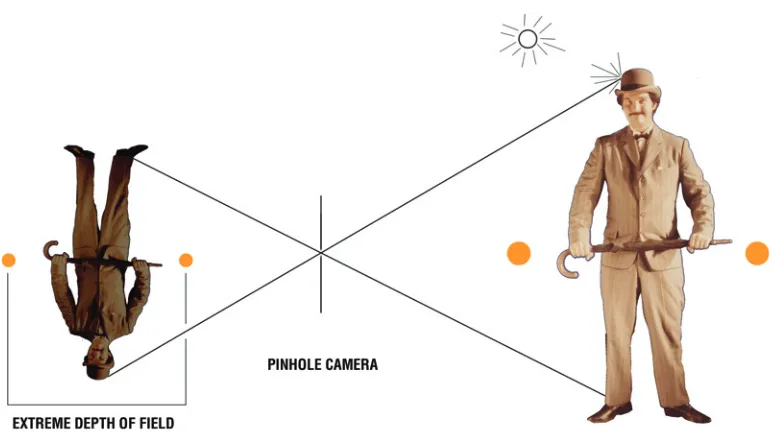
The Pinhole Camera
The one common denominator of all visual effects photography, be it fi lm, video, or digital, is the all-important lens. Consumer digital cameras have invisible lens controls save for a zoom button. Due to automation, the focal length, focus ring, and f-stop are hidden from the operator, which makes it diffi cult for the beginner to get a handle on lens concepts. To bring the reader up to speed fairly quickly, I’ll start by discussing an imaging device that came before lenses. Yes, that’s right; before glass an image could be focused on a surface using nothing more than a tiny hole in a thin fi lm of metal called a pinhole. As early as the sixteenth century, artists used specially constructed portable darkrooms consisting of an imaging surface (such as an artist’s canvas) and a tiny hole on the opposing side to image the world for tracing purposes. The seventeenth-century Dutch painter Vermeer utilized this “camera obscura” in his work.
diffuse surface as opposed to a shiny one). The pinhole allows only a tiny cluster of rays emanating from a point on the surface of the subject to make their way through the hole to form a point of light on the imaging surface. If this phenomenon is repeated for all those selected bundles of rays bouncing off each point of the subject, it forms an upside-down image on the canvas.
For those readers who wear glasses, you can experience the same effect by removing your spectacles and viewing the world through a tiny hole formed by curling your forefi nger as tight as you can while still allowing light to pass through the center of the curl. You will begin to see things in focus without spectacles. The tinier the hole, the fewer bundles of light and the sharper the image becomes. The drawback to this camera obscura was that it was very dim and could only be used on the brightest of days. If the hole is made bigger, more bundles of light pass through, but instead of tight little circles of light forming an image, bigger blur circles are made that start over-lapping with the other circles, creating an unclear image. When the blur circles are small, a sharp picture is produced; when they are larger, a soft or out-of-focus picture is produced. To get a sharp picture, a tiny hole that captures perhaps one percent or less of the bundle of light being refl ected off an object must be used, but the resulting image is very dim. The next step was to somehow make the image brighter.
Refraction and the Lens
Chapter 1: One-Eyed Magic
and when moving through glass light really hits the brakes, moving at 120,000 miles per second. When light goes from a lighter to denser medium such as from air to glass, the rays of light bend. Lenses are shaped to make maximum use of this bending, or refraction, enabling the capture of many more bundles of rays emitting from a subject and bending them all to a “bright” point of focus (Figure 1.2).
When using a lens, the point of light is bright because the lens is capturing 10 percent or more of the rays bouncing off the subject. This is a new phenomenon in that there is only a short range of a sweet spot for the focus of the lens on the canvas that will render the image sharp. Objects in front of or behind the subject will be focused slightly in front of or behind the canvas and will be imaged as out of focus on the canvas or image plane. This limited focus range is known as a narrow depth of fi eld. This means that there will be a certain area in front of and behind the subject that will be in focus while the rest will be progressively softer. This narrow depth of fi eld is not necessarily a bad thing; cinematographers use it all the time to focus the audi-ence’s attention on the subject matter. Closeups of actors often have out-of-focus backgrounds so that the viewer can concentrate on the performers’ expressions. Con-versely, increased depth of fi eld can be used to include more details of the space and is very useful when doing certain types of effects that we will explore later in this chapter.
Focal Length
18 mm, 29 mm, 32 mm, 40 mm, 50 mm, 75 mm, 85 mm, and 100 mm. Modern camera lenses have several lens elements within them to correct natural aberrations that occur within optical paths. Manufacturers take all of these “helper” lenses into consideration when determining the aggregate focal length of the modern compound lens. The important thing to note is that motion picture cameras have sets of lenses called hard or prime lenses of varying focal lengths that have specifi c fi elds of view (that is, how much of the world the lens “sees”). There are also zoom lenses of vari-able focal length that can render a wide range of views from a wide angle (a large expanse) to a narrow angle (the closeup).
The Iris and Depth of Field Control
If we insert a diaphragm or iris into the optical path, we can gain control over how many bundles of light rays pass through to our lens (Figure 1.3). With a wide-open stop or aperture, the maximum number of bundles of light go through, and we get a bright image but very little depth of fi eld. If we stop down, or make a tiny hole that will allow only a few bundles of rays to pass, then we will get a very dim image with a large depth of fi eld similar to the pinhole.
The F-Stop
The iris is primarily used to control the amount of light transmitted by the lens onto the recording medium; its secondary function is to regulate the depth of fi eld recorded in each image. The settings for the iris are expressed in numbers called f-stops. The
Chapter 1: One-Eyed Magic
f-number on a lens is obtained by dividing the focal length by the maximum diameter of a ray of light, which passes through the optical axis of the lens. So a 100 mm lens through which passes a beam of light 50 mm wide at its widest aperture is said to be an f/2. I mention this math in passing for those sticklers who need to know the exact origins of things. The important thing to remember about these f-numbers is that they are very useful as an indicator of exposure and depth of fi eld. One of the fi rst things I learned as a cameraman was my f-stop range: f/2, f/2.8, f/4, f/5.6, f/8, f/11, f/16, and f/22.
Each time the f-number goes higher in this range, the iris gets smaller and half the amount of light gets through the lens, thereby dimming the exposure and increasing the depth of fi eld. So f/5.6 lets in half the amount of light of f/4, and f/8 lets in one-quarter the amount of light of f/4 and half the amount of light of f/5.6. Accord-ing to an old joke about master cinematographers, at the bottom of their desk drawers is a little note that says “big number, little hole; small number, big hole.” This, of course, refers to our friend the f-stop.
The Modern Movie Lens
Unlike consumer cameras, whose lenses are bubbles of glass with a single unmarked ring around them, the professional hard lens has two clearly marked rings (Figure 1.4). One is the focus ring, with defi nite feet and inch as well as metric markings that indicate the point of sharp focus when measured from the cameras fi lm plane (the point at which the image is focused on the fi lm itself ). On many professional cameras there is a marking or a convenient hook for connecting a tape measure so as to measure the exact focus. The other ring is the f-stop ring. Some ranges of f-stop go further than I indicated earlier, such as starting at f/1.4 or ending at f/32. A lens that has a large f-stop capability (small number) is known as a fast lens. Some pro lenses have t-stops, which are the same as f-stops except the markings are based on
an exact measurement of light going through the lens as opposed to the physical iris measurement.
The zoom lens has a third ring that indicates the focal length. You might ask why we need single focal length lenses when a zoom lens will do everything. In the past, due to less glass used in hard lenses along with other factors, hard lenses were just plain sharper. With today’s technology, that advantage is less of an argument. I fi nd hard lenses handy for effects work because they lock down one of the many variables, namely, focal length. If you are doing a composite of a foreground with a background that is shot at a different time, it is the best policy to use the same focal length lens when shooting each element. It is much easier to achieve this match with a hard lens because its focal length is fi xed. While a zoom lens can achieve the same result, its fl exibility can be problematic in the confusion of production. You have to be right on top of the zoom lens during shooting to take note of exactly where the focal length was set in order to repeat that setting later. This is easier said than done on a busy set. If you are a notetaker or supervisor you might not get the chance to see the zoom setting before it is changed. When using a hard lens it is much easier to note the focal length since it is fi xed.
Now that we’ve had a brief refresher course on the all-important lens, let’s move on to the birth of visual effects.
The Glass Shot
Chapter 1: One-Eyed Magic
of the missions he was photographing were sunken in and dilapidated. By painting a matte painting of a roof onto the glass in front of the camera, he made it look as if the missions were whole. The trick used two principles of visual effects photography: the single lens and a large depth of fi eld. Having a large depth of fi eld enabled Dawn to keep both the mission and the glass in focus.
Calculators and depth of fi eld tables in books such as the American Cinematographer
Manual or David Samuelson’s “Hands-On” Manual for Cinematographers from Focal
Press provide exact distances of the depth of fi eld for each focal length and f-stop at a particular focus setting. These tables are invaluable to effects cinematographers plan-ning projects such as a glass shot to ensure that all the elements (e.g., the matte painting and the mission) will be in focus. The typical depth of fi eld table, as shown in Figure 1.5, has three main components: the f-stop listing at the top, the focus setting along the side, and the cross-reference for the near and far distances that will be in focus. Note that there are several rows of f-stop numbers from a variety of circle of confusion listings. The circle of confusion refers to the size of the tiny circles of light that a lens forms for each point of an image focused by the lens. The smaller the circle, the more exacting the measure of focus. You will notice that under f/2.8 in the top row, the f-stops progress by a stop for each tighter circle of confusion in order to maintain the same near far distance. For the majority of my work I choose the 1/500 inch circle of confusion. Cinematographers who have exacting demands for focus splits within a shot use the tighter tolerances. For the most part I shoot in-focus elements to be combined later in composite. Since I know that I will have the ability to sharpen or blur an element later in composite, I normally choose the larger circle of confusion for convenience. When I use this chart, I will go to my f-stop, let’s say f/8 (in the top row), and go down to my focus position on the left of the chart, which might be 8 feet, and then read the box where those two rows intersect to come up with a near focus of 5 feet 9.7 inches and a far focus of 13 feet 3 inches. If my subject sits within these distances then I know it will be in focus. This distance is measured from the fi lm plane.
The Nodal Point
Chapter 1: One-Eyed Magic
between your hand and the object stays the same aside from your inability to stay per-fectly still (things will bobble a bit). What you have just done is pan about the nodal point, or the point at which the light rays converge, as if you panned around the center of your pinhole. When you do this, all elements (the hand and the object) stay locked together. This concept allows us to do simple moves on effects, such as the glass shot, without revealing the trick. Using these earliest of principles, we have the basic build-ing blocks of visual effects. The great thbuild-ing is that these principles are universal and can be used with stills, fi lm, video, or digital—any medium that uses a lens.
Drawbacks of the Glass Shot
The principle of the glass shot is easy enough to grasp, but in reality executing one is quite challenging and requires a good amount of artistic skill. One of the challenges facing the artist is changing light conditions. In order to obtain enough light for depth of fi eld to come into play, you are usually shooting outdoors with a constantly moving sun. Painting is not a fast process, and each shadow that is painted will only match for that moment in time. Fortunately, most members of the audience will not notice that the shadows do not match exactly, as long as the direction and intensity are close. In my experience, you have a window of about 30 minutes to an hour to shoot the shot before the effect starts to give itself away. So if you paint a tree on the glass that casts a shadow toward the right and you rough it in at 9 a.m., by the time you fi nish detailing the tree it may be 1 p.m.—all the shadows will have moved directly underneath the real environment, but not in your painting. The solution to this problem would be to come back the next day and shoot the glass shot at 9 a.m. This situation demands that the camera and glass rig are carefully marked as to their position and reassembled exactly the same way the next day. If possible, the best practice is to create a “hot set” situation as is done on an effects stage and leave as much as possible in place to avoid constant realignment. In the case of an outdoor glass shot, I recommend leaving the glass frame and tripod at the location and remov-ing only the camera and paintremov-ing, as they are the most valuable items and can be put back in place in a repeatable manner.
showing how to create a foreground miniature that is simple to build, fl exible (regard-ing shadows), and very forgiv(regard-ing. So, put on your artist’s beret, and we will venture into the world of art and create and execute a foreground miniature composite using a home digital camera.
Building and Shooting a Foreground Miniature
When we put on the artist’s cap, we engage the other side of our brain and enter a “touchy-feely” realm. Even though there are formulas that artists use for perspective or determining composition, art is not easily summed up by an equation. Professional artists have a grounding in perspective, color theory, and composition and use it as a foundation for their work, but freely break rules on occasion because it just plain looks or feels right. Without formal training, the best way to learn is by observation. If you look at imagery and its details, you can fairly quickly pick out the falsehoods of a rep-resentational rendition, be it a painting or visual effect, by comparison with the real thing. With enough practice and skilled observation, you can come to the same con-clusions as the skilled professional: if it looks right, it is right. It is advantageous for those pursuing visual effects photography to attend art classes and practice traditional art skills. You can progress faster by starting with pencil and paper than by starting with software. As the old saying goes, it takes a thousand drawings to get to the one good one. The sooner you get started on those thousand, the better off you’ll be.
The greatest asset you can have when creating a piece of art (especially representa-tional art, like the model we are about to build) is the ability to see and observe the real thing you are creating. Our model will be a miniature street with a crashed air-craft on the pavement. As you go about collecting your materials, take note of the various streets you use in your travels. What color is the asphalt? Does it have many cracks? Are there spots of tar and imperfections on the surface? What kind of painted markings does it have? Are the lines perfectly straight and even? Look at the street at different times of day, in soft light and in glare. If you look carefully, you will discover how wonderfully imperfect the real world is (as if we didn’t know). The great mistake made by beginning model makers working traditionally or with com-puter graphics is that the models they build are far too perfect. They look like plastic toys and don’t have the aging and wear and tear that exists in the real world. We won’t fall into that trap. Let’s move on to the gathering of some basic materials.
Basic Model-Making Materials
Chapter 1: One-Eyed Magic
water-based paint. Foam board consists of two pieces of art card sandwiching a core of Styrofoam. It is very light and sturdy and is easy to cut and paint, so we will use foam board to create our miniature street. The other component of our model is the crashed aircraft, and here we get into some happy imaginative shopping. In the pro-fessional world, models are painstakingly built to specifi c scales using exacting blue-prints. For the purposes of this exercise, we will wing it. Go to your local hobby or craft store and peruse the plastic models aisle. You are about to engage in the practice of “kit bashing,” a term used to describe the practice of cannibalizing commercially available toys or model kits to create unique miniatures for motion picture use. What does your fallen aircraft look like? For this example, I purchased an inexpensive plastic kit in order to obtain the ready-made shape of an airplane.
So, for your model you will need the following materials (Figure 1.6):
• A sheet of foam board (white), approximately 3 × 4 feet • Hot glue and a hot glue gun (a robust model)
• Gray, black, and textured spray paint to create the base tone for the street • Water-based black paint
• A selection of large and small paintbrushes and an old toothbrush • A plastic airplane kit (preferably prepainted)
• A utility knife or X-Acto blade for cutting the foam board • A Dremel or similar tool for cutting apart the plastic model
It is always a good idea to think backward when designing visual effects. In this case, we want to place the model in front of our camera and have it stay in focus. We also want to do a slight pan, so the model will have to be slightly bigger than what the camera will frame. Finally, we want to build the model so that it can be supported easily and so we won’t have to worry about it when we go on location.
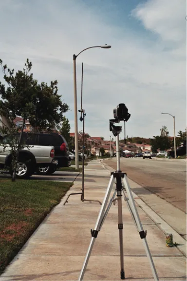
Determining the Size of the Road
Without exhaustive preplanning we can determine focus and size fairly quickly by going outside in lighting conditions similar to those that will be used in our shoot and focusing on a yardstick using the widest angle possible on our consumer video camera. It would be very useful to get a friend to help you, as annoying problems frequently come up, such as your super light tripod blowing over as you’re adjusting your yardstick or the necessity for an assistant to put high-contrast targets on the foreground and background so that you can focus. For this example, I had an assistant move the yardstick toward and away from the camera as I adjusted the focus in the eyepiece until a point was reached at which both the yardstick and the background seemed to be in focus at the same time. Since the quality of the video camera’s eye-piece can be marginal, it is a good idea to shoot a short shot of the yardstick in what you think is the best position, which in this example is the point at which I see 15.5 inches of the yardstick. After you shoot this short test, play it back on a good television set to verify that both the stick and the background are in focus. If the yardstick is soft you may have to position farther back, where, for example, you might see 18 inches of the stick. You will be using your camera’s manual focus setting. I recommend using the widest zoom setting, because wide-angle lenses have more depth of fi eld than longer focal lengths. If I place the yardstick in front of my camera at the point where it and the background are in focus, the widest lens tells me that the front of my model takes up 15.5 inches in the front, and if I make the depth of my model road about 10 inches and move the yardstick 10 inches farther back, then the lens will see 19.5 inches of the stick at the far end. This is our horizontal fi eld of view (Figure 1.7).
Chapter 1: One-Eyed Magic
So, using dead reckoning, which is an educated guess as to how our shot might unfold, we can fi gure that if we made our miniature street 28 inches long, we should have enough to cover our fi eld of view and also allow for a limited pan without having our lens go off the edge of our model. We’ll make the depth of our miniature about 20 inches to allow it to go out the bottom of the frame to ensure that we don’t see the bottom edge of our model road. As for mounting, we’ll use a small, sturdy workbench and attach the model to it using convenient spring clamps. I use this dead reckoning approach a great deal in my work, as my assignments often involve general ideas that need to be realized in a practical manner with the ability to accommodate change. In this case, by making the length of the street 28 inches long, a variety of pans could be accommodated before shooting off the end of the model.
Painting
For our street we will start with the base color by painting the surface with a texture paint that matches the tone of the real street. There are many fabulous spray paints available today that can simulate sandstone, rock, and even chrome. Be sure to look at the sample texture painted on the cap of the can and make sure that the texture is tiny enough to scale in to the real road. Remember, our road is only 2 feet wide, whereas the real street is about 20 feet wide. If the texture is too course it will look as if our street has large boulders and furrows, so keep it subtle. In this case, after I sprayed the texture coat I let it dry and went over it with a wash of gray spray paint to tone down the texture a bit (Figure 1.8).
Next, take a utility knife and cut a jagged crater hole toward the center edge of your model street (Figure 1.9). Remember that we want to make sure that our depth of fi eld
will keep both the model and the background in focus. Placing the crater at the far end of our model road (away from the camera) puts it into the “safe zone” for focus. What I consider the safe zone is anything that is farther back from the point at which the yardstick was in focus in the test. This ensures that the crater will be well within the sharp depth of fi eld region. Make your crater very irregular and organic and save the leftover pieces to create a debris fi eld. Cut jagged cracks emanating from the crater hole, remembering not to make anything uniform in appearance.
After cutting and sculpting the foam, we will take a mid-size brush and use black paint to accentuate the cracks and make uneven roadway stains. For this step I used an almost dry brush and the technique of pouncing, or pounding the brush very rapidly onto the surface to gently stipple in the tone so that it creates a natural feath-ering (Figure 1.10).
We can also use thicker black paint atop a toothbrush and spatter black dots to give the appearance of oil spills, etc. (Figure 1.11).
For our aircraft I roughly assembled the model kit and then artistically disintegrated it using a Dremel tool with a cutting wheel (Figure 1.12). Always wear goggles and a dust mask when working with power tools such as this, as it is very easy for small pieces to get away from you. When cutting the fuselage, I made sure that there was enough of a “profi le” of the model so that it will be perceived as aircraft wreckage.
Mounting the Model
Chapter 1: One-Eyed Magic
glue the model at the far side away from the camera so that the big globs of glue won’t appear in the picture and give the trick away. The glue is extremely hot when it exits the gun and can be very painful should some land on your skin. As a precau-tion, I always keep a container of cool water nearby to dip my hand into should an accident occur (Figure 1.13).
Aging
The fi nal detail painting involves loosely pouncing in scuff and burn marks onto the fuselage (Figure 1.14). This model is extremely small, and the more you can break up the smooth surface of the model, the less it will look like a toy. Another trick is to spray on a fi lm of dulling spray over the model. This mottles the surface and thus Figure 1.10: Pouncing the black paint into the crater.
lessens the chance of getting a big smooth glare off the surface, which is also a dead giveaway that you are using a model. After the fi nal detailing the model is ready for photography.
Finding the Nodal Point
Finding the nodal point on any camera is a simple process of trial and error. The important step is to come up with a device that will allow you to slide the camera forward and backward in relationship to the pivot point of your tripod. For this exercise I used a small strip of metal with a hole for mounting it to the tripod and Figure 1.12: The model can be cut with a Dremel tool, hacksaw, or utility blade. Be sure to wear protective gear!
Chapter 1: One-Eyed Magic
a slot that allows me to mount the camera and slide it forward and back (Figure 1.15). This mounting device is not found in any store but can be either manufactured or repurposed from another application. I will leave this as a mild creative challenge to the reader, as it is part of the visual effects craft to make “gizmos.” You know the objective (to make a movable camera mount); now run out to the hardware store and come up with something that will perform the task. To fi nd the nodal point, position two posts in front of the camera so they appear to be next to each other. One post should be close to the camera and the other farther back. Position the camera so that the center of the lens is over the tripod head (this is a good starting point). Now pan the camera and see whether the posts move in relationship to each other (Figures 1.16–1.19).
Figure 1.14: The fi nal aging of the model.
Figure 1.16: My camera is bolted so that it can slide forward and backward in the slot toward and away from the center of rotation of the tripod. The camera was positioned so that the center of the lens is atop the pivot point of the tripod. This is a good starting position for fi nding the nodal point.
Chapter 1: One-Eyed Magic
If not on nodal, move the camera forward or back slightly, lock it down, and pan again. You will have achieved nodal point when there is no change in the gap between the poles. Remember that each focal length will have a separate nodal position because the optical center of the lens changes as you adjust the focal length. For this shot, always keep the lens at the widest position so you have a repeatable situation. In other words, if you achieve nodal at your test site at the wide position, it will still hold true when you move the camera nodal rig and position it for the model as long as you have locked down the camera and use the widest lens setting. Once you reposition the camera on the miniature, you can double-check the nodal position by panning on the model. If there is any “slide,” you can make last-minute adjustments before executing the shot. Note that this setup only allows you to pan on the nodal. A tilt on nodal would require a much more elaborate rig. A professional nodal rig is shown in Figure 8.4.
The Composite
Set up a table facing the street and mount your model to it. Position the camera with its nodal point mount at the same distance from the model that you had from the Figure 1.18: If objects move toward and away from each other when panning, you are not on nodal.
yardstick you viewed earlier. In this case, if you set the yardstick on the miniature road just in front of the crater you should see 15.5 inches when the camera is set at the widest zoom setting. This will ensure that everything from the yardstick back (including the model) will be in focus. Move the camera up and down and adjust tilt until the back of the miniature road aligns with the bottom of the curb on the opposite sidewalk (Figure 1.20). The front of the road should go out the bottom of frame. This alignment of street and curb will be our convenient “split line,” or the place where the two elements join. This example is known as a “hard split,” which is usually diffi cult to hide, but since the roadway is so different in tone from the curb we buy it as a logical transition and the join works well. Set the camera to manual focus and adjust so that both the model and the background are in focus. Turn off the auto focus to avoid any unwanted changes in focus as you pan the camera. Posi-tion the actors on the opposite sidewalk and have them react to the model aircraft as if it were full size. Pan with them as they walk down the sidewalk and have the wreckage come into view. As you can see, this is an extremely effective visual effect, as the shadows always match the background and we have the ability to move the camera.
Chapter 1: One-Eyed Magic
to correspond to the model in the eyepiece. In the performance, the actor should react to this other object, having it represent the model.
Remember that the foreground miniature effect only works for a fi xed focal length. If you were to zoom in during the shot, the model and background would begin to pull away from each other, so you must always leave the lens at one focal length. This simple technique can create some truly wonderful results (Figure 1.22). The important thing to remember from this exercise is that the majority of visual effects Figure 1.21: Side view of the foreground miniature setup. The two boxes below the workbench were used to level the miniature road since I was on a slanted driveway. Note the spring clamps attaching the foam board to the wooden table, ensuring that the surface was fl at and yet easily adjustable. The dotted line indicates the split line between the two elements. The white card was only used for this illustration as a background to show the placement of the video camera.
boil down to very simple ideas. When elements are shot separately, it is the best policy to shoot each element as if it were part of a single “in camera” composite such as this one. The image elements will combine perfectly if we take care to use the same focal length, focus setting, f-stop, lighting, and camera position (station point) for each element. If, for example, we shot our background in side lighting with a wide-angle lens and then shot the model in front of a blue screen with a long focal length lens with lighting coming from the top, there would be no way to get those two elements to “marry up” and look convincing. This is why grabbing an image from a totally unrelated shot to stick in to another shot is a generally bad idea that rarely looks correct.
Chapter 2
The Fabulous Art of Matte Painting
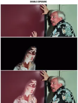
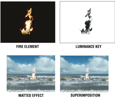
of the fi re’s hold-out matte” refers to a black shadow image of the fi re “holding out” the background image and how opaque the fi re matte was to light. Mattes can obscure either 100% of the light they are holding back or merely a percentage. No matte at all would lead to the superimposition effect, whereas a 50% density would let half the amount of light through leading to a slightly transparent element, which is good for effects such as fi re and smoke that by nature are slightly transparent. Even though digital cameras can’t re-expose on a second pass like fi lm cameras, they still make use of mattes in postprocessing operations.
In digital, the matte is referred to as an alpha channel or key. The alpha channel is used as an elaborate switch in software to determine which image gets turned on and which gets turned off or how much of an image gets blended with another, such as when a foreground is composited over a background. There are several methods for producing an alpha channel. Three of the most common are the drawn or rotoscope method, in which the matte is made by hand; a color difference key known as green screen and blue screen, in which the matte is derived from the difference in color between the subject and the colored screen; and the ever-popular luminance key, in which the matte is obtained from the brightness values of the subject. In the case of the fl ame example in Figure 2.3, the brightest part of the image creates the most density. When using fi lm, printing the color negative onto high-contrast black-and-white fi lm creates a luminance record. The resulting matte is clear in the area that was black and has a variety of densities in the fl ame area. If this matte were placed over a print of a background element in order to rephotograph the image, the matte would dim the exposure of the background in the areas where it has density. On a second pass, the fl ame against black would be exposed, allowing its image to come through at a variety of exposures from 100% (the white part of the fl ame) to a partial exposure when the fl ame is orange. To merely superimpose the fl ame, the background would be photographed without a matte and then the fi lm re-exposed to the fl ame on black. The black prevents re-exposure of the background in that area and allows the fl ame to double-expose over the background. In digital, the same effect is achieved by blending both elements over each other using a “screen” method. In this case the software analyzes the brightness values of both images and does an add mix of the values to re-create the superimposition effect as used in fi lm. You can view this effect in Photoshop by creating two image layers and blending them using the screen option.
Preserving Image Integrity
Chapter 2: The Fabulous Art of Matte Painting
again. Each time you make a copy of a copy, the image gains in contrast and loses detail. A cardinal rule in effects is to have each shot look like the one before it so that the imagery doesn’t “bump.” The duplication problems were so severe in the 1950s that many fi lms, such as Forbidden Planet, would duplicate the fi lm only during transitional effects such as dissolves and then would cut back to the original negative. In the dissolves that appear throughout that fi lm, the shot changes from regular quality to poor quality just as the dissolve takes place; as soon as the event ends, the incoming shot changes back to regular quality.
While the latent image technique involves no duplication, it does require great skill and fortitude since the effects person must work with the original negative. One mistake, and the priceless negative is altered for good. Needless to say, the methods had to be well thought out and foolproof. I was fortunate to work with Albert Whitlock, Bill Taylor, and Syd Dutton at Illusion Arts, where the age-old tradition of latent image matte paintings was still practiced well into the last decade of the twentieth century. What follows is a step-by-step outline of how this brilliant system was utilized by Illusion Arts.
Chapter 2: The Fabulous Art of Matte Painting
Previsualization
Long before Photoshop, matte painters were held in high esteem and valued for their contribution to realizing the exotic locations of a movie. To start this process, the director and producer came to the shop with a script and an idea, such as having their character go to Dracula’s castle. After discussing with the director the feel of the type of castle he or she had in mind, the matte artist usually drew two pre-production sketches on butcher paper, one sketch refl ecting one artistic direction (for example, a low, squat castle with broken battlements), the other refl ecting a different approach (a tall, Gothic castle with spires rising to a stormy sky). The client often chose elements from both sketches, and so a third composite sketch was then made to confi rm the fi nal look.
This procedure was a wonderful way to involve the client and lock in a direction. One unfortunate drawback of the digital world is that everyone is empowered by paint programs and thus fancies themselves as artists. Instead of narrowing down the possibilities for the look, this empowerment often leads to an ever-expanding vision. The challenge for today’s effects artist is to rein in the temptation to throw everything into a shot just because it can be done. The matte painter’s sketches hold together with the simple integrity of a painting with a single vision. When everything gets thrown into a shot via committee, it reads false. The time-tested question to ask is “What is the shot about?”
The Scout
In many instances, the painter went to the location ahead of time with the produc-tion personnel to plan where to place the camera, work out the time of the shoot, and decide whether special platforms need to be built and how much time to allow for that construction. The type of fi lm, the format, and any special considerations such as blue screen foreground were worked out at this stage.
Preparation
Chapter 2: The Fabulous Art of Matte Painting
eter (absolute 24 frames per second). Owning the camera allowed the operator to periodically shoot steady tests and focus tests to ensure that the camera was a reliable instrument.
Further preparation included redundancy. Batteries and motors occasionally fail on location so two of each of those items were always included. The specialized gear consisted of a very sturdy tripod or wooden platform that enabled the camera to be “locked down.” In the latent image technique, unlike the foreground miniature shot outlined earlier, the camera could not move. If moves were needed, they were added later using duplication techniques. A special frame was built to allow for the construc-tion of a matte in front of the camera lens. This frame was a super large matte box that placed a matte about 2 feet in front of the lens to obtain a slightly soft edge. The main camera package consisted of the following:
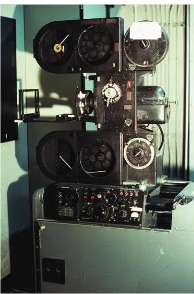
• Camera, typically a Mitchell Fries, which was capable of multiple camera speeds and had a through-the-lens viewfi nder with a place to insert a viewing clip (more on this later)
• Two camera magazines • Two sets of batteries • Sturdy tripod
• A lockable tripod pan and tilt head • Special matte frame
• Set of camera lenses: 18 mm, 24 mm, 32 mm, 50 mm, 85 mm with fi lters
• Black matte card and black duvateen fabric for creating the matte • AKS kit
• A wheeled transportation cart to carry the items
The AKS kit contained any number of extraneous items that might be needed on location, such as clothespins, camera tape, duct tape, sticks of wood, razor blades, C-clamps, screws, bolts, a canvas bag, rope for lifting equipment up to high platforms, and a battery-powered drill. This gave rise to the name AKS, which stands for all kinds of stuff.
Camera Bag
The personal camera bag of the operator was very important as well. Mine contained the following items:
• A light meter (incident and spot) plus mini gray card (more on this later) • A tape measure and inclinometer (to measure distance and angle of the
camera)
Chapter 2: The Fabulous Art of Matte Painting
• A note pad
• Extra fi lm cores and black bags (a fi lm core is the plastic hub that raw stock is wrapped around)
• Pens, pencil, grease pencil, dry erase marker, and portable slate • Leather gloves (for handling hot lights)
• Clothespins, C-clamps, spring clamps
• A hat, sunscreen, sunglasses, salt tablets, and aspirin (there are many times when you are not briefed as to where you are going, and you don’t want to be taken to the middle of the desert without these items)
• American Cinematographer’s Manual
• Mini tool kit (screwdrivers, etc.) scissors, fl ashlight, dust mask • Lens cleaner, cloth, canned air
The Shoot
On a typical shoot day I arrived at perhaps 5:30 a.m. to wait for the production truck to load our equipment and the crew and take us to the location. Upon arrival, we contacted the unit production manager to get our bearings and to fi nd our set-up location. If time permitted, the crew grabbed coffee and a bit of breakfast before getting down to business. After the meal, the crew set up the tripod and camera, ensuring that the camera was level horizontally and would be fi ne-tuned to the matte painter and director’s wishes. Matte painting shots are usually establishing shots that are wide angle views. We typically used an 18 mm lens. Once the composition was fi nalized, the crew began to construct the matte on the big matte frame. Usually this was a two-person operation: the painter looked through the camera and gave com-mands to the grip and operator to raise or lower the black card on the frame to coincide with the area in which the painting would go. The matte would be subtly shaped to create an uneven matte line that would disguise any obvious split. After the matte was created, the frame was blacked in using black cloth extending to the camera to ensure that no stray light contaminated the black area. During this prepa-ration phase, the fi lm magazines were taken to the production camera truck and loaded with the raw stock set aside by the Director of Photography to execute the shot. This step ensured that the composite was made on the same stock that the cine-matographer chose to shoot the movie on. This guaranteed a consistent look to the-photography. The exposure setting was usually given by the Director of Photography to further match the fi lmmaker’s intent.
Shoot Procedure
This test run was removed from the take-up magazine and both sides were examined for scratches or damage. After the determination that the camera was functioning well, the fi lm was “seated” against the aperture in its exposure position and a white grease pencil mark was made on the fi lm along the straight edge of the camera gate. This mark indicated the frame line position on the raw stock.
A tiny side notch was also cut out of the edge of the fi lm as a guide for start and stop points when winding back the fi lm in the dark.
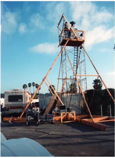
Figure 2.7: A shot of a matte frame with a black card matte in front of the camera. Matte painter Mark Whitlock is standing next to the rig. Mark and I were sent to an extinct volcano in Hawaii to shoot this plate. The funny thing was that much of the background wound up being matted out, as can be seen on the matte box. We replaced so much of the background with a painting that the matte shot could have been done in Burbank. I didn’t mind the trip to Hawaii, though. Courtesy of Illusion Arts.
Chapter 2: The Fabulous Art of Matte Painting
After the camera was set, the camera height, tilt angle, lens, focus, light direction, f-stop, and any other possibly helpful information were recorded to be able to recreate the camera setup later should it be necessary. After this was done, all that remained was to wait for the actors and director to take their places. When the actors and director arrived, the effects camera was ready to roll.
The shoot order was as follows:
• Shoot take one, including about 20 feet of preroll before action, noting footage and the director’s comments, such as “That was great” or “So-so.” This helped rate the takes. After each take, the camera door was opened, the fi lm was seated, and a grease pencil line and notch in the fi lm were made.
Figure 2.9: Marking the frame line.
• Shoot take two and repeat the above steps.
• Shoot take three and repeat until the director was satisfi ed.
After the required number of takes was shot, a 400 foot run of test footage was photographed. The test footage does not require actors; only the background scenery is needed. This footage will be used to develop and test the painting, thereby pre-serving the precious takes for the fi nal composites. After this shot we again put in a grease pencil mark and a notch.
The fi nal element to shoot was a small bit of footage to send to the lab for processing to check the exposure and provide imagery to begin the painting process. First a burst of fi lm was shot with the matte, then the matte was removed and a burst was shot without the matte. Finally the camera tilt was brought back to level and a burst of level camera was shot. The camera was then broken down and both the camera package crew and fi lm were taken back to the effects studio.
Darkroom Procedure
When back at the studio, the fi lm magazine was taken to the darkroom and placed next to a pair of fi lm rewinds. A number of prepared cans, labels, and black bags were set aside to contain all the takes, the test footage, and the “with and without/ level camera” exposure. If it was a dry day we ensured that the room was humidifi ed, and we were prepared to wind back the fi lm slowly, as quickly winding fi lm creates static electricity and spark exposures on the partially exposed fi lm. With the lights out, I began winding the fi lm taken out of the take-up magazine onto fi lm cores, tail to head, feeling the edges of the fi lm for the notches that I made during the shoot. At each notch I broke the fi lm and put that roll into the appropri-ate can. I repeappropri-ated this process until I fi lled each can, then turned on the lights after ensuring that the cans were taped securely. I double-checked my notes with the number of cans and the amount of fi lm. The 400 foot test footage will always be the heaviest can. I then sent the with and without/level camera roll to the lab for developing and printing. The other cans were placed in the freezer to arrest any chemical change the fi lm undergoes after exposure. Some fi lms allow latent exposures to redden with time, even before development, if left out at room temperature.
Studio Procedure
Chapter 2: The Fabulous Art of Matte Painting
camera is unique in that it also serves as a projector, allowing the live action element to be imaged onto the painting surface for tracing purposes.
A large fi berboard sheet with frame was placed in the easel against a repeatable “pin stop” to ensure that the painting could be returned to the same place for each effects shoot. The process of projecting the negative onto the easel and tracing is called rotoscoping and is used in both traditional and digital techniques. Essentially, it is the hand drawing of mattes derived from previously shot footage either by projection or by drawing on a computer. The matte line was traced along with a brief sketch of the live action element. A reference was taken of the middle of the frame of the level camera negative and then transferred to the shot angle and drawn out as the horizon. When a picture is taken at level camera, the horizon line will always be center frame. To illustrate the importance of level camera, I’ll set aside the current example from Figure 2.8 and move to an illustration of a house extension and sky replacement painting.
Figure 2.12 is a shot taken at level camera. Lines drawn from each corner of the frame intersect at the center, showing exactly where the horizon is. You can see how important the establishing of the horizon is by projecting lines from the window frames on the building at the right. The projected lines meet at the vanishing point, which rests upon the horizon. These vanishing points are very handy in order to keep paintings of buildings in the correct perspective.
The blowup of the picture in Figure 2.13 shows a convenient reference point where the horizon line intersected an object, in this case, the top of a window frame. We Figure 2.12: By going to the level camera clip and bisecting the frame, the horizon line can be deter-mined. Note how the vanishing point for the edges of the window is at the horizon line.
Chapter 2: The Fabulous Art of Matte Painting
used this information to transfer the horizon line to its proper position on the actual frame, which had a tilt. Another benefi t of shooting level camera is that the approxi-mate height of the camera can be found. In this case I was shooting from a hill looking down. I had the actress stand next to the light pole as a reference. In Photo-shop I cut and pasted her on top of herself to use her as an organic measuring device. Since she was about 5.5 feet tall, I got a fairly good idea of the camera height by counting the fi gures. Obtaining the camera height by picture analysis is handy should you need to shoot another element that needs to fi t into this photograph. In this case it would have been diffi cult to measure the height on location, as I was on a gently sloping hill instead of a tall platform.
Figure 2.14 shows the actual shot. We transferred the horizon line to the proper position on this photograph and used it as a guide for drawing perspective lines. This ensured that our set extension diminished in perspective accurately. In this case the painting was a clone of the building at the right, but there was more to it than a straight copy. The clone had to be scaled in size and the roof rotated so that it fell within those all-important perspective lines. One of the many skills a good matte painter must master is matching perspective. Correct perspective is a critical compo-nent of a believable matte painting. I’ll now return to the traditional example.
The Painting
the previously exposed live action element. The basic procedure for creating a matte painting is to go from rough to detailed. It is a process of constant refi nement. When the fi rst rough in of the painting was done, it went in front of the matte camera to shoot the fi rst exposure test.
Exposure Wedges
The painting was placed in a holder and lit by eight lightbulbs at the top and eight at the bottom that were run at a voltage of 90 volts. The reason for this was twofold. Shooting with 16 lights was a redundancy scheme that precluded lightbulb failure from ruining an original negative shot. If a composite was done with two lights on either side of a painting and one light blew out during the exposure of the latent fi lm, the error would be irreversible. If one bulb out of 16 failed, the subtle dimming would likely not be noticed. Running the bulbs at 90 volts instead of the customary 110 volts was a cost-saving measure that greatly extended the life of the bulbs. The bulbs were also switched on and off instead of being slowly brought up to full bright-ness via a dimmer. The sudden shock to a bulb when it is instantly turned on tends to cause it to fail at that moment, which is better than having it fail while the camera is shooting. Another fail-safe idea.
Chapter 2: The Fabulous Art of Matte Painting
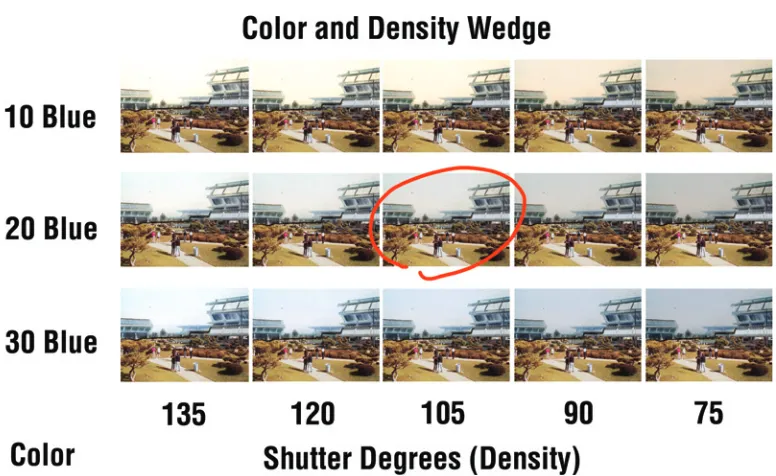
shorten the exposure times in very small increments, such as 170, 150, 135, 120, 105, 90, 75, 65, 58, and 50 degrees. Using the camera shutter in this manner lessened the need for putting any more fi lters into the light path than were necessary. A neutral density fi lter could be eliminated if the proper exposure could be arrived at from f-stop and shutter. The idea was to hit the correct exposure in the middle of the wedge at around 105 degrees. With each wedge the artist would be able to see the painting brighter and darker, which gave insight into what the tones were doing as the painting was being created.
To start, the test footage was threaded into the matte camera and the grease pencil line was used to ensure that it was threaded on the frame line. A short burst of the painting was shot, perhaps 2 feet, and the camera room was then turned into a darkroom and the short test piece was removed and quickly processed using a dip test method. The dip test consisted of dunking the fi lm into developer for about a minute and then removing it to a fi xing bath to “fi x,” or keep the processed image from fading. After processing, the dip test was examined in the light to make sure that the camera was threaded on the frame line and that the painting was exposing over the proper area of the fi lm. To cut down on the amount of waste, the exposed fi lm was allowed to pile up inside the camera body instead of being threaded into the magazine take-up chamber.
A typical wedge was based on a guess exposure derived from the sensitivity of the fi lm ISO and the amount of light used. When the dip test was approved, a slate was photographed for 1 foot and 14 frames. There are 16 frames or pictures in 35 mm fi lm, which left two frames before the 2 foot mark to leave blank (in the painting area) to act as a visual separation before the wedge. The fi rst wedge consisted of putting a 10 blue fi lter behind the lens using a convenient slot and shooting one frame for each of the shutter positions mentioned earlier. One frame of black was shot as a separation, then the 10 blue was replaced with a 10 blue (10b) plus 10 cyan (10c) fi lter and the shutter range was shot again. Following this, 20b, then 20b 10c, then 20b 20c were wedged in that order. After the wedges, a 2 foot burst at the guess exposure was shot as a “normal.” When the wedges were fi nished, all lights were turned off in the camera room and the shooting port through which the camera viewed the painting was closed to allow the camera to be downloaded without fogging the fi lm. Since there was only 400 feet of test footage, as little fi lm as possible needed to be used for each wedge. The customary 2 feet on either end was a safe zone to allow for handling in the fi lm lab. Typically each wedge was only 5 feet in length. This short amount was awkward for labs accustomed to thousands of feet of fi lm, but they were accommodating. The wedge was canned up and sent to the lab for development with a called light print. A called light print is one for which the lab is given three specifi c numbers for the amount of red, green, and blue light to use when making the print. These three numbers are established via a variety of tests and then are locked as a way to avoid having the lab make a “timed” print, where they determine the color of the lights used to make the print. The camera report typically indicated “Develop as normal; make one print at red 23, green 22, blue 20 on printer C5.” Specifying the printer to be used also limited the variables and allowed the artist to have full control. Two prints made with the same lights on dif-ferent printers can be slightly difdif-ferent, so that possibility was eliminated.
Dailies
Chapter 2: The Fabulous Art of Matte Painting
Sky Mattes
Matte paintings are static. A degree of realism can be obtained if movement can be introduced into the picture. One of the standard methods for giving life to a painting is the animation of the sky. This brilliant trick was devised by Albert Whitlock himself. The idea is to make the painting oversized so that the east–west border goes beyond the fi eld of view of the camera. This allows room to pull the painting hori-zontally to impart movement to the clouds. This is accomplished with the use of three mattes placed about 1 foot away from the lens of the matte camera. The mattes were pieces of tape placed upon 4 × 5 inch sheets of glass held in a frame. Matte number one revealed the uppermost portion of the sky containing the foreground clouds. Matte number two exposed the mid-sky region, and matte number three exposed the sky horizon and the rest of the matte painting. To make the matte lines or “join” between the mattes invisible, one glass would be placed atop the other in register in order to place the “countermatte.” To do this I viewed the refl ection of the pupil of my eye in the glass so that it rested atop the edge of the tape forming the matte. I then placed a piece of tape across from the fi rst matte to form the coun-termatte. This method also ensured that I created an even gap between both mattes to create a seamless blend between one exposure and the other. When a scene was photographed through a soft matte, the image fell off into darkness gradually. If a countermatte was made with a gap, then this fall off was replicated and the two soft edges falling off to 50 percent in the penumbra of the matte shadow combined to make a blended 100% exposure. Blending a matte this way can be thought of as creating a mini-dissolve within the blend of the two pictures. If the gap is too big, the two exposures will overlap and create a bright superimposition, resulting in a “white” matte line. If the gap is too small or overlapping, there will be no exposure between the two exposures, resulting in a “black” matte line. The painter accom-plishes this blending by using stippling or dithering methods to blend the painting into the black paint.
Sky Animation
was shooting at a speed of 4 frames per second, so we made the following calculations:
Projector fi lm speed = 24 frames per second
Frames = 16 frames per foot × 40 feet = 640 frames
Matte painting camera speed = 4 frames per second
Real time = 640 frames ÷ 4 frames per second = 160 seconds to shoot the shot
Painting speed = 160 seconds ÷ 8 inches = 20 seconds per inch
As I operated the camera, the master grip, Lynn Ledgerwood, pulled the painting by means of a hand crank operating a lead screw that slowly moved the painting. At fi rst glance this may seem a primitive technique in this age of computers and motors, but manual animation of a latent image painting made a great deal of sense. Since there was no going back on a latent shot, it was critical to have a real-time human component at the wheel. If a mathematical miscalculation was noticed during the actual shoot, then the camera operator would tell the painting mover to slow down or speed up to avoid catastrophe. A mechanical clock was used for the timing. After a timing test to get the speed of the hand crank to yield 1 inch every 20 seconds, the fi rst matte, revealing the foreground sky, was inserted, the frame counter was set to zero, and the fi rst animated exposure commenced. After this pass, the painting was positioned 2 inches past the center mark (the fi rst pass was started 4 inches past center, since the move was 8 inches in total) and the speed was reset to 1 inch every 40 seconds. The camera was rewound (with the shutter closed) to zero, and the second pass with the mid-ground cloud matte inserted was exposed. After the second expo-sure, the lower matte was inserted, and the painting was positioned on the center mark and left static for the fi nal exposure. The result was a wonderful effect of not only clouds that moved but also clouds that changed and drifted apart as they became lost in the soft matte lines of the splits, truly an elegant matte painting motion enhance-ment. It worked so well partly because it was matting the same thing over itself so the integrity of both elements was fl awless. This trick carries over even into the digital age.
Painting Enhancements
Miniatures
Chapter 2: The Fabulous Art of Matte Painting
foreground miniatures do not need mattes. The lighting could be controlled and viewed as it would appear, so blending issues were easily dealt with.
Printed-in Elements
Next, smoke coming from chimneys was inserted into the shot by using the camera as a contact printer. A roll of fi lm containing smoke elements against black was threaded up against the latent image roll in the camera using a technique called “bipack.” The painting was removed, and a black matte with a tiny window in the area above the location of the chimney on the matte painting was used to send light through the lens of the camera through the smoke element and “print the smoke” above the chimney as a double exposure onto the latent shot.