Chapter 28
Direct Current Circuits
C H A P T E R O U T L I N E
28.1
Electromotive Force
28.2
Resistors in Series and
Parallel
28.3
Kirchhoff’s Rules
28.4
RC
Circuits
28.5
Electrical Meters
28.6
Household Wiring and
Electrical Safety
▲
An assortment of batteries that can be used to provide energy for various devices. Batteries provide a voltage with a fixed polarity, resulting in a direct currentin a circuit, that is, a current for which the drift velocity of the charges is always in the same direction. (George Semple)T
his chapter is concerned with the analysis of simple electric circuits that contain batteries, resistors, and capacitors in various combinations. We will see some circuits in which resistors can be combined using simple rules. The analysis of more complicated circuits is simplified using two rules known as Kirchhoff’s rules, which follow from the laws of conservation of energy and conservation of electric charge for isolated systems. Most of the circuits analyzed are assumed to be in steady state, which means that currents in the circuit are constant in magnitude and direction. A current that is constant in direction is called a direct current (DC). We will study alternating current (AC), in which the current changes direction periodically, in Chapter 33. Finally, we describe electrical meters for measuring current and potential difference, and discuss electrical circuits in the home.28.1
Electromotive Force
In Section 27.6 we discussed a closed circuit in which a battery produces a potential difference and causes charges to move. We will generally use a battery in our discus-sion and in our circuit diagrams as a source of energy for the circuit. Because the potential difference at the battery terminals is constant in a particular circuit, the current in the circuit is constant in magnitude and direction and is called direct current.A battery is called either a source of electromotive forceor, more commonly, a source of emf.(The phrase electromotive forceis an unfortunate historical term, describ-ing not a force but rather a potential difference in volts.) The emf of a battery is the maximum possible voltage that the battery can provide between its terminals.You can think of a source of emf as a “charge pump.” When an electric potential difference exists between two points, the source moves charges “uphill” from the lower potential to the higher.
Consider the circuit shown in Figure 28.1, consisting of a battery connected to a resistor. We shall generally assume that the connecting wires have no resistance.
!
859 +
Resistor Battery –
The positive terminal of the battery is at a higher potential than the negative termi-nal. Because a real battery is made of matter, there is resistance to the flow of charge within the battery. This resistance is called internal resistancer. For an idealized bat-tery with zero internal resistance, the potential difference across the batbat-tery (called its terminal voltage) equals its emf. However, for a real battery, the terminal voltage is not equal to the emf for a battery in a circuit in which there is a current. To understand why this is so, consider the circuit diagram in Figure 28.2a, where the battery of Figure 28.1 is represented by the dashed rectangle containing an ideal, resistance-free emf in series with an internal resistance r. Now imagine moving through the battery from ato band measuring the electric potential at various locations. As we pass from the negative terminal to the positive terminal, the potential increases by an amount . However, as we move through the resistance r, the potential decreases by an amount Ir, where I is the current in the circuit. Thus, the terminal voltage of the battery "V#Vb$Vais1
"V# $Ir (28.1)
From this expression, note that is equivalent to the open-circuit voltage—that is, the terminal voltage when the current is zero.The emf is the voltage labeled on a battery— for example, the emf of a D cell is 1.5 V. The actual potential difference between the terminals of the battery depends on the current in the battery, as described by Equa-tion 28.1.
Figure 28.2b is a graphical representation of the changes in electric potential as the circuit is traversed in the clockwise direction. By inspecting Figure 28.2a, we see that the terminal voltage "Vmust equal the potential difference across the external resis-tance R, often called the load resistance.The load resistor might be a simple resistive circuit element, as in Figure 28.1, or it could be the resistance of some electrical device (such as a toaster, an electric heater, or a lightbulb) connected to the battery (or, in the case of household devices, to the wall outlet). The resistor represents a loadon the battery because the battery must supply energy to operate the device. The potential dif-ference across the load resistance is "V#IR.Combining this expression with Equation 28.1, we see that
#IR%Ir (28.2)
Solving for the current gives
(28.3)
This equation shows that the current in this simple circuit depends on both the load resistance Rexternal to the battery and the internal resistance r. If Ris much greater than r, as it is in many real-world circuits, we can neglect r.
If we multiply Equation 28.2 by the currentI, we obtain
I #I2R%I2r (28.4)
This equation indicates that, because power !#I "V(see Eq. 27.22), the total power output I of the battery is delivered to the external load resistance in the amount I2R and to the internal resistance in the amount I2r. terminal voltage may exceed the emf by an amount Ir.This happens when the direction of the current is opposite that of the emf, as in the case of charging a battery with another source of emf.
a c this case, a battery), of internal resistance r, connected to an external resistor of resistance R. (b) Graphical representation showing how the electric potential changes as the circuit in part (a) is traversed clockwise.
At the Active Figures link at http://www.pse6.com,you can adjust the emf and resistances r and R to see the effect on the current and on the graph in part (b).
!
▲
PITFALL PREVENTION
28.1
What Is Constant in a
Battery?
It is a common misconception that a battery is a source of constant current. Equation 28.3 clearly shows that this is not true. The current in the circuit depends on the resistance connected to the battery. It is also not true that a battery is a source of constant terminal voltage, as shown by Equation 28.1. A battery is a source of constant emf.
S E C T I O N 2 8 . 1 • Electromotive Force 861
Example 28.1 Terminal Voltage of a Battery
A battery has an emf of 12.0 V and an internal resistance of 0.05'. Its terminals are connected to a load resistance of 3.00'.
(A) Find the current in the circuit and the terminal voltage of the battery.
Solution Equation 28.3 gives us the current:
and from Equation 28.1, we find the terminal voltage:
"V# $Ir#12.0 V$(3.93 A)(0.05')#
To check this result, we can calculate the voltage across the load resistance R:
"V#IR#(3.93 A)(3.00')#11.8 V
(B) Calculate the power delivered to the load resistor, the power delivered to the internal resistance of the battery, and the power delivered by the battery.
Solution The power delivered to the load resistor is
!
R#I2R#(3.93 A)2(3.00')#
The power delivered to the internal resistance is
!r#I2r#(3.93 A)2(0.05')# 0.772 W
46.3 W 11.8 V
!
3.93 A
I#
!
R%r #
12.0 V 3.05 ' #
Hence, the power delivered by the battery is the sum of these quantities, or 47.1 W. You should check this result, using the expression !#I .
What If? As a battery ages, its internal resistance increases. Suppose the internal resistance of this battery rises to 2.00! toward the end of its useful life. How does this alter the ability of the battery to deliver energy?
Answer Let us connect the same 3.00-'load resistor to the battery. The current in the battery now is
and the terminal voltage is
"V# $I r#12.0 V$(2.40 A) (2.00')#7.2 V
Notice that the terminal voltage is only 60% of the emf. The powers delivered to the load resistor and internal resistance are
!R#I2R#(2.40 A)2 (3.00')#
!r#I2r#(2.40 A)2 (2.00')#11.5 W
Notice that 40% of the power from the battery is delivered to the internal resistance. In part (B), this percentage is 1.6%. Consequently, even though the emf remains fixed, the increasing internal resistance significantly reduces the ability of the battery to deliver energy.
17.3 W
!
I#
!
R%r #
12.0 V
(3.00 ' %2.00 ') #2.40 A
!
Interactive
Example 28.2 Matching the Load
Show that the maximum power delivered to the load resis-tance R in Figure 28.2a occurs when the load resistance matches the internal resistance—that is, when R#r.
Solution The power delivered to the load resistance is equal to I2R, where Iis given by Equation 28.3:
When !is plotted versus Ras in Figure 28.3, we find that !reaches a maximum value of 2/4rat R#r. When Ris
large, there is very little current, so that the power I2R
delivered to the load resistor is small. When R is small, the current is large and there is significant loss of power
I2ras energy is delivered to the internal resistance. When
R#r, these effects balance to give a maximum transfer of power.
We can also prove that the power maximizes at R#rby differentiating !with respect to R, setting the result equal
!
!#I2R#!
2R(R%r)2
to zero, and solving for R. The details are left as a problem for you to solve (Problem 57).
At the Interactive Worked Example link at http://www.pse6.com,you can vary the load resistance and internal resistance, observing the power delivered to each.
r 2r 3r R
!max !
Figure 28.3 (Example 28.2) Graph of the power !delivered
2 The term voltage dropis synonymous with a decrease in electric potential across a resistor and is
used often by individuals working with electric circuits.
28.2
Resistors in Series and Parallel
Suppose that you and your friends are at a crowded basketball game in a sports arena and decide to leave early. You have two choices: (1) your group can exit through a single door and push your way down a long hallway containing several concession stands, each sur-rounded by a large crowd of people waiting to buy food or souvenirs; or (2) each member of your group can exit through a separate door in the main hall of the arena, where each will have to push his or her way through a single group of people standing by the door. In which scenario will less time be required for your group to leave the arena?
It should be clear that your group will be able to leave faster through the separate doors than down the hallway where each of you has to push through several groups of people. We could describe the groups of people in the hallway as being in series,because each of you must push your way through all of the groups. The groups of people around the doors in the arena can be described as being in parallel. Each member of your group must push through only one group of people, and each member pushes through a different group of people. This simple analogy will help us understand the behavior of currents in electric circuits containing more than one resistor.
When two or more resistors are connected together as are the lightbulbs in Figure 28.4a, they are said to be in series.Figure 28.4b is the circuit diagram for the lightbulbs, which are shown as resistors, and the battery. In a series connection, if an amount of charge Qexits resistor R1, charge Q must also enter the second resistor R2. (This is analogous to all members of your group pushing through each crowd in the single hallway of the sports arena.) Otherwise, charge will accumulate on the wire between the resistors. Thus, the same amount of charge passes through both resistors in a given time interval. Hence,
The potential difference applied across the series combination of resistors will divide between the resistors. In Figure 28.4b, because the voltage drop2from ato bequals IR
1 and the voltage drop from bto cequals IR2, the voltage drop from ato cis
"V#IR1%IR2#I(R1%R2)
for a series combination of two resistors, the currents are the same in both resis-tors because the amount of charge that passes through R1must also pass through
R2in the same time interval.
+ –
(a)
Battery
R1 R2
∆V
(c)
I
+ –
a c
(b) I
R1 R2
I
+ –
a b c
I1 = I2 = I Req = R1 + R2
∆V
Active Figure 28.4(a) A series connection of two lightbulbs with resistances R1and R2. (b) Circuit diagram for the two-resistor circuit. The current in R1is the same as that in R2. (c) The resistors replaced with a single resistor having an equivalent resistance Req#R1%R2.
The potential difference across the battery is also applied to the equivalent resistance Reqin Figure 28.4c:
"V#IReq
where we have indicated that the equivalent resistance has the same effect on the circuit because it results in the same current in the battery as the combination of resis-tors. Combining these equations, we see that we can replace the two resistors in series with a single equivalent resistance whose value is the sumof the individual resistances:
"V#IReq#I(R1%R2) 9: Req#R1%R2 (28.5)
The resistance Req is equivalent to the series combination R1%R2in the sense that the circuit current is unchanged when Reqreplaces R1%R2.
The equivalent resistance of three or more resistors connected in series is
(28.6)
This relationship indicates that the equivalent resistance of a series connection of resistors is the numerical sum of the individual resistances and is always greater than any individual resistance.
Looking back at Equation 28.3, the denominator is the simple algebraic sum of the external and internal resistances. This is consistent with the fact that internal and external resistances are in series in Figure 28.2a.
Note that if the filament of one lightbulb in Figure 28.4 were to fail, the circuit would no longer be complete (resulting in an open-circuit condition) and the second bulb would also go out. This is a general feature of a series circuit—if one device in the series creates an open circuit, all devices are inoperative.
Req#R1%R2%R3% ( ( (
S E C T I O N 2 8 . 2 • Resistors in Series and Parallel 863
The equivalent resistance of several resistors in series
▲
PITFALL PREVENTION
28.2
Lightbulbs Don’t
Burn
We will describe the end of the life of a lightbulb by saying that
the filament fails, rather than by
saying that the lightbulb “burns out.” The word burn suggests a combustion process, which is not what occurs in a lightbulb.
Quick Quiz 28.2
In Figure 28.4, imagine positive charges pass first throughR1 and then through R2. Compared to the current in R1, the current in R2 is
(a) smaller, (b) larger, or (c) the same.
Quick Quiz 28.3
If a piece of wire is used to connect points band cin Figure 28.4b, does the brightness of bulb R1(a) increase, (b) decrease, or (c) remain the same?Quick Quiz 28.4
With the switch in the circuit of Figure 28.5 closed (left), there is no current in R2, because the current has an alternate zero-resistance paththrough the switch. There is current in R1and this current is measured with the
amme-ter (a device for measuring current) at the right side of the circuit. If the switch is opened (Fig. 28.5, right), there is current in R2. What happens to the reading on the
ammeter when the switch is opened? (a) the reading goes up; (b) the reading goes down; (c) the reading does not change.
A R1
Switch closed
R2 A
R1
Switch open R2
(c)
Active Figure 28.6 (a) A parallel connection of two lightbulbs with resistances R1and
R2. (b) Circuit diagram for the two-resistor circuit. The potential difference across R1is
the same as that across R2. (c) The resistors replaced with a single resistor having an
equivalent resistance given by Equation 28.7.
Now consider two resistors connected in parallel, as shown in Figure 28.6. When charges reach point ain Figure 28.6b, called a junction,they split into two parts, with some going through R1and the rest going through R2. A junction is any point in a circuit where a current can split (just as your group might split up and leave the sports arena through several doors, as described earlier.) This split results in less current in each indi-vidual resistor than the current leaving the battery. Because electric charge is conserved, the current Ithat enters point amust equal the total current leaving that point:
I#I1%I2
where I1is the current in R1and I2is the current in R2.
As can be seen from Figure 28.6, both resistors are connected directly across the terminals of the battery. Therefore,
when resistors are connected in parallel, the potential differences across the resis-tors is the same.
▲
PITFALL PREVENTION
28.3
Local and Global
Changes
A local change in one part of a circuit may result in a global change throughout the circuit.
For example, if a single resistance is changed in a circuit containing several resistors and batteries, the currents in all resistors and batter-ies, the terminal voltages of all bat-teries, and the voltages across all resistors may change as a result.
▲
PITFALL PREVENTION
28.4
Current Does Not
Take the Path of
Least Resistance
You may have heard a phrase like “current takes the path of least resistance” in reference to a par-allel combination of current paths, such that there are two or more paths for the current to take. The phrase is incorrect. The current takes all paths. Those paths with lower resistance will have large currents, but even very high-resistance paths will carry someof the current.
Because the potential differences across the resistors are the same, the expression
"V#IRgives
where Req is an equivalent single resistance which will have the same effect on the circuit as the two resistors in parallel; that is, it will draw the same current from the battery (Fig. 28.6c). From this result, we see that the equivalent resistance of two resis-tors in parallel is given by
An extension of this analysis to three or more resistors in parallel gives
(28.8)
We can see from this expression that the inverse of the equivalent resistance of two or more resistors connected in parallel is equal to the sum of the inverses of the individual resistances. Furthermore, the equivalent resistance is always less than the smallest resistance in the group.
Household circuits are always wired such that the appliances are connected in par-allel. Each device operates independently of the others so that if one is switched off, the others remain on. In addition, in this type of connection, all of the devices operate on the same voltage.
1
Req
# 1 R1
% 1 R2
% 1 R3
% ( ( (
S E C T I O N 2 8 . 2 • Resistors in Series and Parallel 865
The equivalent resistance of several resistors in parallel
Quick Quiz 28.5
In Figure 28.4, imagine that we add a third resistor in series with the first two. Does the current in the battery (a) increase, (b) decrease, or (c) remain the same? Does the terminal voltage of the battery (d) increase, (e) decrease, or (f) remain the same?Quick Quiz 28.6
In Figure 28.6, imagine that we add a third resistor in parallel with the first two. Does the current in the battery (a) increase, (b) decrease, or (c) remain the same? Does the terminal voltage of the battery (d) increase, (e) decrease, or (f) remain the same?Quick Quiz 28.7
With the switch in the circuit of Figure 28.7 open (left), there is no current in R2. There is current in R1and this current is measured with theammeter at the right side of the circuit. If the switch is closed (Fig. 28.7, right), there is current in R2. What happens to the reading on the ammeter when the switch is closed?
(a) the reading goes up; (b) the reading goes down; (c) the reading does not change.
Switch open
R1
R2
Switch closed A
R1
R2
A
Figure 28.7 (Quick Quiz 28.7) What happens when the switch is closed?
Conceptual Example 28.3 Landscape Lights
A homeowner wishes to install 12-volt landscape lighting in his back yard. To save money, he purchases inexpensive 18-gauge cable, which has a relatively high resistance per unit length. This cable consists of two side-by-side wires separated by insulation, like the cord on an appliance. He runs a 200-foot length of this cable from the power supply to the farthest point at which he plans to position a light fixture. He attaches light fixtures across the two wires
Solution A circuit diagram for the system appears in Figure 28.8. The horizontal resistors (such as RA and RB)
represent the resistance of the wires in the cable between the light fixtures while the vertical resistors (such as RC)
represent the resistance of the light fixtures themselves. Part of the terminal voltage of the power supply is dropped across resistors RA and RB. Thus, the voltage across light
fixture RC is less than the terminal voltage. There is a
further voltage drop across resistors RD and RE.
Conse-quently, the voltage across light fixture RFis smaller than
that across RC. This continues on down the line of light
fixtures, so the correct choice is (b). Each successive light fixture has a smaller voltage across it and glows less brightly than the one before.
RA RD
RC RF
RB RE
Resistance of light fixtures
Resistance in wires of cable
Power supply
Figure 28.8 (Conceptual Example 28.3) The circuit diagram for a set of landscape light fixtures connected in parallel across the two wires of a two-wire cable. The horizontal resistors represent resistance in the wires of the cable. The vertical resistors represent the light fixtures.
Example 28.4 Find the Equivalent Resistance
Four resistors are connected as shown in Figure 28.9a.
(A) Find the equivalent resistance between points aand c.
Solution The combination of resistors can be reduced in steps, as shown in Figure 28.9. The 8.0-'and 4.0-'resistors are in series; thus, the equivalent resistance between aand b
is 12.0 '(see Eq. 28.5). The 6.0-'and 3.0-'resistors are in parallel, so from Equation 28.7 we find that the equivalent resistance frombto cis 2.0 '. Hence, the equivalent resis-tance from ato cis 14.0 '.
(B) What is the current in each resistor if a potential differ-ence of 42 V is maintained between aand c?
Solution The currents in the 8.0-'and 4.0-'resistors are the same because they are in series. In addition, this is the same as the current that would exist in the 14.0-'equivalent resistor subject to the 42-V potential difference. Therefore, using Equation 27.8 (R# "V/I) and the result from part (A), we obtain
This is the current in the 8.0-'and 4.0-'resistors. When this 3.0-A current enters the junction at b, however, it splits, with part passing through the 6.0-' resistor (I1) and part
through the 3.0-'resistor (I2). Because the potential
differ-ence is "Vbc across each of these parallel resistors, we see
that (6.0 ')I1#(3.0 ')I2, or I2#2I1. Using this result and
the fact that I1%I2#3.0 A, we find that I1#1.0 A and I# "Vac
Req
# 42 V
14.0 ' #3.0 A
I2#2.0 A. We could have guessed this at the start by noting
that the current in the 3.0-'resistor has to be twice that in the 6.0-'resistor, in view of their relative resistances and the fact that the same voltage is applied to each of them.
As a final check of our results, note that "Vbc#
(6.0')I1#(3.0')I2#6.0 V and "Vab#(12.0')I#36 V;
therefore, "Vac# "Vab% "Vbc#42 V, as it must.
6.0 Ω
3.0 Ω c b
I1
I2
4.0 Ω 8.0 Ω
a
c 2.0 Ω 12.0 Ω
b a
14.0 Ω
c a
(a)
(b)
(c) I
Figure 28.9 (Example 28.4) The original network of resistors is reduced to a single equivalent resistance.
Example 28.5 Finding Reqby Symmetry Arguments
Consider five resistors connected as shown in Figure 28.10a. Find the equivalent resistance between points aand b.
Solution If we inspect this system of resistors, we realize that we cannot reduce it by using our rules for series and parallel
Example 28.6 Three Resistors in Parallel
Three resistors are connected in parallel as shown in Figure 28.11a. A potential difference of 18.0 V is maintained between points aand b.
(A) Find the current in each resistor.
Solution The resistors are in parallel, and so the potential difference across each must be 18.0 V. Applying the relation-ship "V#IRto each resistor gives total power delivered to the combination of resistors.
Solution We apply the relationship !#I2Rto each
resis-tor and obtain
This shows that the smallest resistor receives the most power. Summing the three quantities gives a total power of 198 W.
Figure 28.11 (Example 28.6) (a) Three resistors connected in parallel. The voltage across each resistor is 18.0 V. (b) Another circuit with three resistors and a battery. Is this equivalent to the circuit in part (a) of the figure?
Interactive Thus, the 5-'resistor may be removed from the circuit and
the remaining circuit then reduced as in Figures 28.10c and d. From this reduction we see that the equivalent resistance of the combination is 1'. Note that the result is 1' regard-less of the value of the resistor connected between cand d.
(c)
Conceptual Example 28.7 Operation of a Three-Way Lightbulb
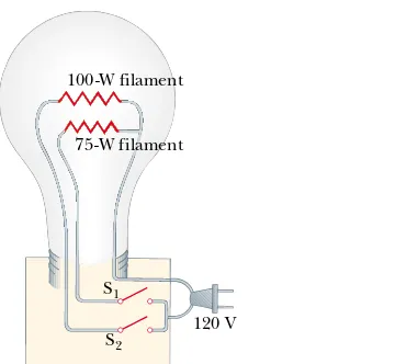
Figure 28.12 illustrates how a three-way lightbulb is con-structed to provide three levels of light intensity. The socket of the lamp is equipped with a three-way switch for selecting different light intensities. The bulb contains two filaments. When the lamp is connected to a 120-V source, one filament receives 100 W of power, and the other receives 75 W. Explain how the two filaments are used to provide three different light intensities.
Solution The three light intensities are made possible by applying the 120 V to one filament alone, to the other fi la-ment alone, or to the two filaments in parallel. When switch S1is closed and switch S2 is opened, current exists only in
the 75-W filament. When switch S1is open and switch S2 is
closed, current exists only in the 100-W filament. When both switches are closed, current exists in both filaments, and the total power is 175 W.
If the filaments were connected in series and one of them were to break, no charges could pass through the bulb, and the bulb would give no illumination, regardless of the switch position. However, with the filaments connected
in parallel, if one of them (for example, the 75-W filament) breaks, the bulb will still operate in two of the switch posi-tions as current exists in the other (100-W) filament.
120 V 100-W filament
75-W filament
S1 S2
Figure 28.12 (Conceptual Example 28.7) A three-way lightbulb.
Application Strings of Lights
Strings of lights are used for many ornamental purposes, such as decorating Christmas trees.3 Over the years, both
parallel and series connections have been used for strings of lights powered by 120 V. Series-wired bulbs are safer than parallel-wired bulbs for indoor Christmas-tree use because series-wired bulbs operate with less energy per bulb and at a lower temperature. However, if the filament of a single bulb fails (or if the bulb is removed from its socket), all the lights on the string go out. The popularity of series-wired light strings diminished because troubleshooting a failed bulb was a tedious, time-consuming chore that involved trial-and-error substitution of a good bulb in each socket along the string until the defective bulb was found.
In a parallel-wired string, each bulb operates at 120 V. By design, the bulbs are brighter and hotter than those on
a series-wired string. As a result, these bulbs are inherently more dangerous (more likely to start a fire, for instance), but if one bulb in a parallel-wired string fails or is removed, the rest of the bulbs continue to glow. (A 25-bulb string of 4-W bulbs results in a power of 100 W; the total power becomes substantial when several strings are used.)
A new design was developed for so-called “miniature” lights wired in series, to prevent the failure of one bulb from causing the entire string to go out. This design creates a connection (called a jumper) across the filament after it fails. When the filament breaks in one of these miniature lightbulbs, the break in the filament represents the largest resistance in the series, much larger than that of the intact filaments. As a result, most of the applied 120 V appears across the bulb with the broken filament. Inside the
3 These and other household devices, such as the three-way lightbulb in Conceptual Example 28.7
and the kitchen appliances discussed in Section 28.6, actually operate on alternating current (AC), to be introduced in Chapter 33.
(C) Calculate the equivalent resistance of the circuit.
Solution We can use Equation 28.8 to find Req:
1.64 '
Req#
18.0 ' 11.0 # 1
Req
# 1
3.00 ' % 1 6.00 ' %
1 9.00 '
What If? What if the circuit is as shown in Figure 28.11b instead of as in Figure 28.11a? How does this affect the calculation?
Answer There is no effect on the calculation. The physical placement of the battery is not important. In Figure 28.11b, the battery still applies a potential difference of 18.0 V between points aand b, so the two circuits in Figure 28.11 are electrically identical.
28.3
Kirchhoff’s Rules
As we saw in the preceding section, simple circuits can be analyzed using the expres-sion "V#IR and the rules for series and parallel combinations of resistors. Very often, however, it is not possible to reduce a circuit to a single loop. The procedure for analyzing more complex circuits is greatly simplified if we use two principles called Kirchhoff ’s rules:
S E C T I O N 2 8 . 3 • Kirchhoff’s Rules 869
lightbulb, a small jumper loop covered by an insulating material is wrapped around the filament leads. When the filament fails and 120 V appears across the bulb, an arc burns the insulation on the jumper and connects the filament leads. This connection now completes the circuit through the bulb even though its filament is no longer active (Fig. 28.13).
Suppose that all the bulbs in a 50-bulb miniature-light string are operating. A 2.40-V potential drop occurs across each bulb because the bulbs are in series. A typical power input to this style of bulb is 0.340 W. The filament resis-tance of each bulb at the operating temperature is (2.40 V)2/(0.340 W)#16.9 '. The current in each bulb is
2.40 V/16.9 ' #0.142 A. When a bulb fails, the resistance across its terminals is reduced to zero because of the alternate
jumper connection mentioned in the preceding paragraph. All the other bulbs not only stay on but glow more brightly because the total resistance of the string is reduced and con-sequently the current in each bulb increases.
Let us assume that the resistance of a bulb remains at 16.9' even though its temperature rises as a result of the increased current. If one bulb fails, the potential difference across each of the remaining bulbs increases to 120 V/49# 2.45 V, the current increases from 0.142 A to 0.145 A, and the power increases to 0.355 W. As more bulbs fail, the current keeps rising, the filament of each bulb operates at a higher temperature, and the lifetime of the bulb is reduced. For this reason, you should check for failed (nonglowing) bulbs in such a series-wired string and replace them as soon as possible, in order to maximize the lifetimes of all the bulbs.
Figure 28.13 (a) Schematic diagram of a modern “miniature” holiday lightbulb, with a jumper connection to provide a current path if the filament breaks. When the filament is intact, charges flow in the filament. (b) A holiday lightbulb with a broken filament. In this case, charges flow in the jumper connection. (c) A Christmas-tree lightbulb.
George Semple
Filament
Jumper
Glass insulator
(b) (a)
I I
I
1. Junction rule. The sum of the currents entering any junction in a circuit must equal the sum of the currents leaving that junction:
(28.9)
2. Loop rule.The sum of the potential differences across all elements around any closed circuit loop must be zero:
(28.10)
#
closedloop
"V#0
#
Iin##
IoutKirchhoff’s first rule is a statement of conservation of electric charge. All charges that enter a given point in a circuit must leave that point because charge cannot build up at a point. If we apply this rule to the junction shown in Figure 28.14a, we obtain
I1#I2%I3
Figure 28.14b represents a mechanical analog of this situation, in which water flows through a branched pipe having no leaks. Because water does not build up anywhere in the pipe, the flow rate into the pipe equals the total flow rate out of the two branches on the right.
Kirchhoff’s second rule follows from the law of conservation of energy. Let us imagine moving a charge around a closed loop of a circuit. When the charge returns to the starting point, the charge–circuit system must have the same total energy as it had before the charge was moved. The sum of the increases in energy as the charge passes through some circuit elements must equal the sum of the decreases in energy as it passes through other elements. The potential energy decreases whenever the charge moves through a potential drop $IR across a resis-tor or whenever it moves in the reverse direction through a source of emf. The potential energy increases whenever the charge passes through a battery from the negative terminal to the positive terminal.
When applying Kirchhoff’s second rule in practice, we imagine traveling around the loop and consider changes in electric potential,rather than the changes in potential energy
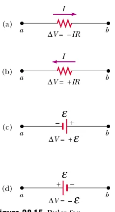
described in the preceding paragraph. You should note the following sign conventions when using the second rule:
• Because charges move from the high-potential end of a resistor toward the low-potential end, if a resistor is traversed in the direction of the current, the poten-tial difference "Vacross the resistor is $IR(Fig. 28.15a).
• If a resistor is traversed in the direction opposite the current, the potential
differ-(Fig. 28.15d). In this case the emf of the battery reduces the electric potential as we move through it.
Limitations exist on the numbers of times you can usefully apply Kirchhoff’s rules in analyzing a circuit. You can use the junction rule as often as you need, so long as each time you write an equation you include in it a current that has not been used in a preceding junction-rule equation. In general, the number of times you can use the junction rule is one fewer than the number of junction points in the circuit. You can apply the loop rule as often as needed, as long as a new circuit element (resistor or battery) or a new current appears in each new equation. In general, in order to solve a particular circuit problem, the number of independent equations you need to obtain from the two rules equals the number of unknown currents.
Complex networks containing many loops and junctions generate great numbers of independent linear equations and a correspondingly great number of unknowns. Such situations can be handled formally through the use of matrix algebra. Computer software can also be used to solve for the unknowns.
The following examples illustrate how to use Kirchhoff’s rules. In all cases, it is assumed that the circuits have reached steady-state conditions—that is, the currents in the various branches are constant. Any capacitor acts as an open branch in a circuit; that is, the current in the branch containing the capacitor is zero under differences across a resistor and a battery. (The battery is assumed to have no internal resistance.) Each entering a junction must leave that junction. Therefore, I1#I2%I3.
S E C T I O N 2 8 . 3 • Kirchhoff’s Rules 871
Gustav Kirchhoff
German Physicist (1824–1887) Kirchhoff, a professor at Heidelberg, and Robert Bunsen invented the spectroscope and founded the science of spectroscopy, which we shall study in Chapter 42. They discovered the elements cesium and rubidium and invented astronomical spectroscopy. (AIP ESVA/W.F. Meggers Collection)
P R O B L E M - S O LV I N G H I N T S
Kirchhoff’s Rules
•
Draw a circuit diagram, and label all the known and unknown quantities. You must assign a direction to the current in each branch of the circuit. Although the assignment of current directions is arbitrary, you must adhere rigorously to the assigned directions when applying Kirchhoff’s rules.•
Apply the junction rule to any junctions in the circuit that provide new relationships among the various currents.•
Apply the loop rule to as many loops in the circuit as are needed to solve for the unknowns. To apply this rule, you must correctly identify the potential difference as you imagine crossing each element while traversing the closed loop (either clockwise or counterclockwise). Watch out for errors in sign!•
Solve the equations simultaneously for the unknown quantities. Do not be alarmed if a current turns out to be negative; its magnitude will be correct and the direction is opposite to that which you assigned.Quick Quiz 28.8
In using Kirchhoff’s rules, you generally assign a separate unknown current to (a) each resistor in the circuit (b) each loop in the circuit (c) each branch in the circuit (d) each battery in the circuit.Example 28.8 A Single-Loop Circuit
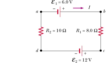
A single-loop circuit contains two resistors and two batteries, as shown in Figure 28.16. (Neglect the internal resistances of the batteries.)
(A) Find the current in the circuit.
Solution We do not need Kirchhoff’s rules to analyze this simple circuit, but let us use them anyway just to see how they are applied. There are no junctions in this single-loop circuit; thus, the current is the same in all elements. Let us assume that the current is clockwise, as shown in Figure 28.16. Traversing the circuit in the clockwise direction, starting at a, we see that a:brepresents a potential differ-ence of % 1, b:c represents a potential difference of $IR1, c:drepresents a potential difference of $
!
2, and!
d:arepresents a potential difference of $IR2. Applying
Kirchhoff’s loop rule gives
Solving for Iand using the values given in Figure 28.16, we obtain
The negative sign for Iindicates that the direction of the current is opposite the assumed direction. Notice that the emfs in the numerator subtract because the batteries have opposite polarities in Figure 28.16. In the denominator, the resistances add because the two resistors are in series.
(B) What power is delivered to each resistor? What power is delivered by the 12-V battery?
Solution Using Equation 27.23,
Hence, the total power delivered to the resistors is
!1%!2#2.0 W.
The 12-V battery delivers power I 2#4.0 W. Half of this
power is delivered to the two resistors, as we just calculated. The other half is delivered to the 6-V battery, which is being
!
1.1 W
!
2#I2R2#(0.33 A)2(10 ')#
0.87 W
!
1#I2R1#(0.33 A)2(8.0 ')#
$0.33 A
(1)
I#
!
1$!
2R1%R2
# 6.0 V$12 V 8.0 ' %10 ' #
!
1$IR1$!
2$IR2#0#
"V#0a I b
c d
1 = 6.0 V
+
– R1 = 8.0 Ω
R2 = 10 Ω
2 = 12 V
+
–
ε
ε
charged by the 12-V battery. If we had included the internal resistances of the batteries in our analysis, some of the power would appear as internal energy in the batteries; as a result, we would have found that less power was being delivered to the 6-V battery.
What If? What if the polarity of the 12.0-V battery were reversed? How would this affect the circuit?
Answer While we could repeat the Kirchhoff’s rules calculation, let us examine Equation (1) and modify it accordingly. Because the polarities of the two batteries are
now in the same direction, the signs of 1and 2 are the
same and Equation (1) becomes
The new powers delivered to the resistors are
!1#I2R
1#(1.0 A)2(8.0')#8.0 W
!2#I2R2#(1.0 A)2(10')#10 W
This totals 18 W, nine times as much as in the original circuit, in which the batteries were opposing each other.
I#
!
1%!
2R1%R2
# 6.0 V%12 V
8.0 ' %10 ' #1.0 A
!
!
Example 28.9 Applying Kirchhoff’s Rules
Find the currents I1, I2, and I3in the circuit shown in Figure
28.17.
Solution Conceptualize by noting that we cannot simplify the circuit by the rules of adding resistances in series and in parallel. (If the 10.0-V battery were taken away, we could reduce the remaining circuit with series and parallel com-binations.) Thus, we categorize this problem as one in which we must use Kirchhoff’s rules. To analyze the circuit, we arbitrarily choose the directions of the currents as la-beled in Figure 28.17. Applying Kirchhoff’s junction rule to junctioncgives
(1) I1%I2#I3
We now have one equation with three unknowns—I1, I2, and I3. There are three loops in the circuit—abcda, befcb, and
aefda.We therefore need only two loop equations to
deter-mine the unknown currents. (The third loop equation would give no new information.) Applying Kirchhoff’s loop rule to loops abcda and befcb and traversing these loops clockwise, we obtain the expressions
(2) abcda 10.0 V$(6.0')I1$(2.0')I3#0
(3) befcb $14.0 V%(6.0')I1$10.0 V$(4.0')I2#0
Note that in loop befcb we obtain a positive value when traversing the 6.0-'resistor because our direction of travel is opposite the assumed direction of I1. Expressions (1), (2),
and (3) represent three independent equations with three unknowns. Substituting Equation (1) into Equation (2) gives
10.0 V$(6.0')I1$(2.0') (I1%I2)#0
(4) 10.0 V#(8.0')I1%(2.0')I2
Dividing each term in Equation (3) by 2 and rearranging gives
(5) $12.0 V# $(3.0')I1%(2.0')I2
Subtracting Equation (5) from Equation (4) eliminates I2,
giving
22.0 V#(11.0')I1
I1#
Using this value of I1in Equation (5) gives a value for I2:
(2.0')I2#(3.0')I1$12.0 V
#(3.0')(2.0 A)$12.0 V# $6.0 V
I2#
Finally,
I3#I1%I2#
To finalize the problem, note that I2and I3are both
nega-tive. This indicates only that the currents are opposite the direction we chose for them. However, the numerical values are correct. What would have happened had we left the current directions as labeled in Figure 28.17 but traversed the loops in the opposite direction?
$1.0 A $3.0 A
2.0 A
14.0 V e
b 4.0 Ω
– +
10.0 V 6.0 Ω
–
+ f
I2
c I3 I1
2.0 Ω
d a
Figure 28.17 (Example 28.9) A circuit containing different branches.
Interactive
28.4
RC
Circuits
So far we have analyzed direct current circuits in which the current is constant. In DC circuits containing capacitors, the current is always in the same direction but may vary in time. A circuit containing a series combination of a resistor and a capacitor is called an RC circuit.
Charging a Capacitor
Figure 28.19 shows a simple series RCcircuit. Let us assume that the capacitor in this circuit is initially uncharged. There is no current while switch S is open (Fig. 28.19b). If the switch is closed at t#0, however, charge begins to flow, setting up a current in the circuit, and the capacitor begins to charge.4Note that during charging, charges do
4 In previous discussions of capacitors, we assumed a steady-state situation, in which no current was
present in any branch of the circuit containing a capacitor. Now we are considering the case beforethe steady-state condition is realized; in this situation, charges are moving and a current exists in the wires connected to the capacitor.
S E C T I O N 2 8 . 4 • RCCircuits 873
Example 28.10 A Multiloop Circuit
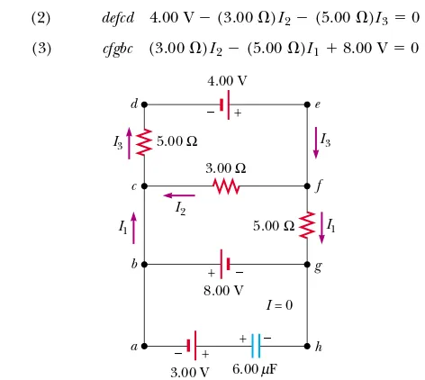
(A) Under steady-state conditions, find the unknown currents
I1, I2, and I3in the multiloop circuit shown in Figure 28.18.
Solution First note that because the capacitor represents an open circuit, there is no current between gand balong path ghab under steady-state conditions. Therefore, when the charges associated with I1 reach point g, they all go
toward point bthrough the 8.00-V battery; hence, Igb#I1.
Labeling the currents as shown in Figure 28.18 and applying Equation 28.9 to junction c, we obtain
(1) I1%I2#I3
Equation 28.10 applied to loops defcd and cfgbc, traversed clockwise, gives
(2) defcd 4.00 V$(3.00')I2$(5.00')I3#0
(3) cfgbc (3.00')I2$(5.00')I1%8.00 V#0
From Equation (1) we see that I1#I3$I2, which, when
substituted into Equation (3), gives
(4) (8.00')I2$(5.00')I3%8.00 V#0
Subtracting Equation (4) from Equation (2), we eliminate I3
and find that
Because our value for I2is negative, we conclude that the
di-rection of I2is from cto fin the 3.00-'resistor. Despite this
interpretation of the direction, however, we must continue to use this negative value for I2 in subsequent calculations
because our equations were established with our original choice of direction.
Using I2# $0.364 A in Equations (3) and (1) gives
(B) What is the charge on the capacitor?
Solution We can apply Kirchhoff’s loop rule to loop bghab
(or any other loop that contains the capacitor) to find the potential difference "Vcap across the capacitor. We use this
potential difference in the loop equation without reference to a sign convention because the charge on the capacitor depends only on the magnitude of the potential difference. Moving clockwise around this loop, we obtain
$8.00 V% "Vcap$3.00 V#0
"Vcap#11.0 V
Because Q#C "Vcap (see Eq. 26.1), the charge on the
capacitor is
Q#(6.00)F)(11.0 V)#
Why is the left side of the capacitor positively charged? 66.0)C
1.02 A
I3#
1.38 A
I1#
$0.364 A
I2# $
4.00 V 11.0 ' #
4.00 V d
c
5.00 Ω
–
+
8.00 V 3.00 Ω
– + e
I3
f I1
I2
5.00 Ω
h a
g
– +
3.00 V
–
+
6.00 F I = 0 b
I3
I1
µ
not jump across the capacitor plates because the gap between the plates represents an open circuit. Instead, charge is transferred between each plate and its connecting wires due to the electric field established in the wires by the battery, until the capacitor is fully charged. As the plates are being charged, the potential difference across the capacitor increases. The value of the maximum charge on the plates depends on the voltage of the battery. Once the maximum charge is reached, the current in the circuit is zero because the potential difference across the capacitor matches that supplied by the battery.
To analyze this circuit quantitatively, let us apply Kirchhoff’s loop rule to the circuit after the switch is closed. Traversing the loop in Fig. 28.19c clockwise gives
(28.11)
where q/Cis the potential difference across the capacitor and IRis the potential differ-ence across the resistor. We have used the sign conventions discussed earlier for the signs on and IR. For the capacitor, notice that we are traveling in the direction from the positive plate to the negative plate; this represents a decrease in potential. Thus, we use a negative sign for this potential difference in Equation 28.11. Note that qand Iare
instantaneous values that depend on time (as opposed to steady-state values) as the capacitor is being charged.
We can use Equation 28.11 to find the initial current in the circuit and the maxi-mum charge on the capacitor. At the instant the switch is closed (t#0), the charge on the capacitor is zero, and from Equation 28.11 we find that the initial currentI0in the circuit is a maximum and is equal to
(28.12)
At this time, the potential difference from the battery terminals appears entirely across the resistor. Later, when the capacitor is charged to its maximum value Q, charges cease to flow, the current in the circuit is zero, and the potential difference from the battery terminals appears entirely across the capacitor. Substituting I#0 into Equation 28.11 gives the charge on the capacitor at this time:
(maximum charge) (28.13)
To determine analytical expressions for the time dependence of the charge and current, we must solve Equation 28.11—a single equation containing two variables,q
and I. The current in all parts of the series circuit must be the same. Thus, the current in the resistance Rmust be the same as the current between the capacitor plates and the
Q#C
!
I0#!
R
(current at t#0)
!
!
$ qC $IR#0 + –
Resistor
Battery Capacitor
Switch
(a)
ε
(b) S
t < 0 R
C
(c)t > 0
ε
R
S
I q
–
+q
Active Figure 28.19 (a) A capacitor in series with a resistor, switch, and battery. (b) Circuit diagram representing this system at time t*0, before the switch is closed. (c) Circuit diagram at time t+0, after the switch has been closed.
wires. This current is equal to the time rate of change of the charge on the capacitor plates. Thus, we substitute I#dq/dtinto Equation 28.11 and rearrange the equation:
To find an expression for q, we solve this separable differential equation. We first combine the terms on the right-hand side:
Now we multiply by dtand divide by q$C to obtain
Integrating this expression, using the fact that q#0 at t#0, we obtain
From the definition of the natural logarithm, we can write this expression as
(28.14)
where eis the base of the natural logarithm and we have made the substitution from Equation 28.13.
We can find an expression for the charging current by differentiating Equation 28.14 with respect to time. UsingI#dq/dt, we find that
(28.15)
Plots of capacitor charge and circuit current versus time are shown in Figure 28.20. Note that the charge is zero at t#0 and approaches the maximum value C as t:,. The current has its maximum value I0# /Rat t#0 and decays exponentially to zero as t:,. The quantity RC, which appears in the exponents of Equations 28.14 and 28.15, is called the time constant - of the circuit. It represents the time interval during which the current decreases to 1/eof its initial value; that is, in a time interval
-, I#e$1I0#0.368I0. In a time interval 2-, I#e$2I0#0.135I0, and so forth. Likewise, in a time interval -, the charge increases from zero to C
!
[1$e$1]#0.632C!
.!
!
I(t)#
!
R e$t/RC
q(t)#C
!
(1$e$t/RC)#Q(1$e$t/RC)ln
!
q$C!
$C
!
"
# $ t RC$
q0
dq
(q$C
!
) # $ 1RC
$
t
0 dt
dq
q$C
!
# $1
RC dt
!
dq dt #
C
!
RC $q RC # $
q$C
!
RC dqdt #
!
R $ q RC
S E C T I O N 2 8 . 4 • RCCircuits 875
Charge as a function of time for a capacitor being charged
Current as a function of time for a capacitor being charged
q
τ t
C 0.632C
(a)
I
τ t
0.368I0
(b) I0 I0 =R
ε
ε
ε
=RC τ
Figure 28.20 (a) Plot of capacitor charge versus time for the circuit shown in Figure 28.19. After a time interval equal to one time constant -has passed, the charge is 63.2% of the maximum value C . The charge approaches its maximum value as tapproaches infinity. (b) Plot of current versus time for the circuit shown in Figure 28.19. The current has its maximum value I0# /Rat t#0 and decays to zero exponentially as t
approaches infinity. After a time interval equal to one time constant -has passed, the current is 36.8% of its initial value.
The following dimensional analysis shows that -has the units of time:
Because - #RChas units of time, the combination -/RCis dimensionless, as it must be in order to be an exponent of e in Equations 28.14 and 28.15.
The energy output of the battery as the capacitor is fully charged is Q #C 2. After the capacitor is fully charged, the energy stored in the capacitor is Q # C 2, which is just half the energy output of the battery. It is left as a problem (Problem 64) to show that the remaining half of the energy supplied by the battery appears as inter-nal energy in the resistor.
Discharging a Capacitor
Now consider the circuit shown in Figure 28.21, which consists of a capacitor carrying an initial charge Q, a resistor, and a switch. When the switch is open, a potential differ-ence Q/Cexists across the capacitor and there is zero potential difference across the resistor because I#0. If the switch is closed at t#0, the capacitor begins to discharge through the resistor. At some time tduring the discharge, the current in the circuit is I
and the charge on the capacitor is q (Fig. 28.21b). The circuit in Figure 28.21 is the same as the circuit in Figure 28.19 except for the absence of the battery. Thus, we elim-inate the emf from Equation 28.11 to obtain the appropriate loop equation for the circuit in Figure 28.21:
(28.16)
When we substitute I#dq/dtinto this expression, it becomes
Integrating this expression, using the fact that q#Qat t#0 gives
(28.17)
Differentiating this expression with respect to time gives the instantaneous current as a function of time:
(28.18)
where Q/RC#I0is the initial current. The negative sign indicates that as the capaci-tor discharges, the current direction is opposite its direction when the capacicapaci-tor was being charged. (Compare the current directions in Figs. 28.19c and 28.21b.) We see that both the charge on the capacitor and the current decay exponentially at a rate characterized by the time constant - #RC.
I(t)# dq resistor and a switch, which is open for t*0. (b) After the switch is closed at t#0, a current that decreases in magnitude with time is set up in the direction shown, and the charge on the capacitor decreases exponentially with time.
At the Active Figures link at http://www.pse6.com,you can adjust the values of R and C to see the effect on the discharging of the capacitor.
Charge as a function of time for a discharging capacitor
Current as a function of time for a discharging capacitor
Quick Quiz 28.9
Consider the circuit in Figure 28.19 and assume that the battery has no internal resistance. Just after the switch is closed, the potential differ-ence across which of the following is equal to the emf of the battery? (a)C (b)RS E C T I O N 2 8 . 4 • RCCircuits 877
Quick Quiz 28.10
Consider the circuit in Figure 28.22 and assume that the battery has no internal resistance. Just after the switch is closed, the current in the bat-tery is (a) zero (b) /2R(c) 2 /R(d) /R(e) impossible to determine. After a very long time, the current in the battery is (f) zero (g) /2R(h) 2 /R(i) /R(j) impos-sible to determine.!
!
!
!
!
!
ε
C
R R
Figure 28.22 (Quick Quiz 28.10) How does the current vary after the switch is closed?
Conceptual Example 28.11 Intermittent Windshield Wipers
Many automobiles are equipped with windshield wipers that can operate intermittently during a light rainfall. How does the operation of such wipers depend on the charging and discharging of a capacitor?
Solution The wipers are part of an RCcircuit whose time constant can be varied by selecting different values of R
through a multiposition switch. As it increases with time, the voltage across the capacitor reaches a point at which it triggers the wipers and discharges, ready to begin another charging cycle. The time interval between the individual sweeps of the wipers is determined by the value of the time constant.
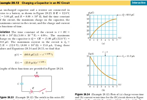
Example 28.12 Charging a Capacitor in an RCCircuit
An uncharged capacitor and a resistor are connected in series to a battery, as shown in Figure 28.23. If #12.0 V,
C#5.00)F, and R#8.00.105', find the time constant
of the circuit, the maximum charge on the capacitor, the maximum current in the circuit, and the charge and current as functions of time.
Solution The time constant of the circuit is - #RC# (8.00.105')(5.00.10$6F)#4.00 s. The maximum
charge on the capacitor is Q#C #(5.00)F)(12.0 V)# 60.0)C. The maximum current in the circuit is I0#
/R #(12.0 V)/(8.00.105')#15.0)A. Using these
values and Equations 28.14 and 28.15, we find that
Graphs of these functions are provided in Figure 28.24. (15.0 )A)e$t/4.00 s
I(t)#
(60.0 )C )(1$e$t/4.00 s)
q(t)#
!
!
!
Interactive
R
ε
C+ – S
0 1 2 3 4 5 6 7 0
10 20 30 40 50 60q(µC)
t(s)
0 1 2 3 4 5 6 7 0
5 10 15I(µA)
t(s) (a)
(b) µ
µ
Q = 60.0 µµC
I0 = 15.0 µµA
t =τ
At the Interactive Worked Example link at http://www.pse6.com,you can vary R, C, and
!
and observe the charge and current as functions of time while charging or discharging the capacitor.Figure 28.23 (Example 28.12) The switch in this series RC circuit, open for times t*0, is closed at t#0.
Example 28.13 Discharging a Capacitor in an RCCircuit
Taking logarithms of both sides, we find
(B) The energy stored in the capacitor decreases with time as the capacitor discharges. After how many time constants is this stored energy one-fourth its initial value?
Solution Using Equations 26.11 (U#Q2/2C) and 28.17, we can express the energy stored in the capacitor at any time tas
U# q
Again, taking logarithms of both sides and solving fortgives
What If? What if we wanted to describe the circuit in terms of the time interval required for the charge to fall to one-half its original value, rather than by the time constant "? This would give a parameter for the circuit called its half-life t1/2.
How is the half-life related to the time constant?
Answer After one half-life, the charge has fallen from Qto
Q/2. Thus, from Equation 28.17,
leading to
t1/2#0.693
-The concept of half-life will be important to us when we study nuclear decay in Chapter 44. The radioactive decay of an unstable sample behaves in a mathematically similar manner to a discharging capacitor in an RCcircuit.
1
Example 28.14 Energy Delivered to a Resistor
A 5.00-)F capacitor is charged to a potential difference of 800 V and then discharged through a 25.0-kV resistor. How much energy is delivered to the resistor in the time interval required to fully discharge the capacitor?
Solution We shall solve this problem in two ways. The first way is to note that the initial energy in the circuit equals the energy stored in the capacitor, C 2/2 (see Eq. 26.11). Once the capacitor is fully discharged, the energy stored in it is zero. Because energy in an isolated system is conserved, the initial energy stored in the capacitor is transformed into in-ternal energy in the resistor. Using the given values of Cand
, we find
The second way, which is more difficult but perhaps more instructive, is to note that as the capacitor discharges through the resistor, the rate at which energy is delivered to the resistor is given by I2R, where I is the instantaneous current given by Equation 28.18. Because power is defined as the rate at which energy is transferred, we conclude that
1.60 J Energy#12C
!
2#21(5.00.10$6 F)(800 V)2#!
!
the energy delivered to the resistor must equal the time inte-gral of I2R dt:
To evaluate this integral, we note that the initial current I0is
equal to /Rand that all parameters except tare constant. Thus, we find
This integral has a value of RC/2 (see Problem 35); hence, we find
which agrees with the result we obtained using the simpler approach, as it must. Note that we can use this second approach to find the total energy delivered to the resistor at
any time after the switch is closed by simply replacing the upper limit in the integral with that specific value of t.