IMPROVEMENT SUGGESTION IN INCINERATOR WASTE ENTRY DOOR
DESIGN USING ULRICH-EPPINGER METHOD
(BANDUNG TECHNO PARK STUDY CASE)
Randy Pradana1, Rino Andias Anugraha ST, MM2, Muhammad Iqbal ST, MM3
1,2,3Industrial Engineering Study Program, School of Industrial and System Engineering, Telkom University
1[email protected], 2[email protected] 3[email protected]
Abstract
Waste problem Indonesia is one of problems that quite difficult to be resolved. Bandung is one of the cities that has a quite serious waste problem. It can be proved by lots of waste that piled up in some main point in Bandung. Then, additional waste treatment is needed for undistributed wastes for reducing wastes accumulation that happens continuously. One types of incinerator is Solair Incinerator that developed by Bandung Techno Park. In this incinerator usage, was found problems related to operator’s body posture and work accident possibilities in the operational usage. By referring to Ulrich-Eppinger product development process that consisted of some stages of development matched with user reuirements, will be generated improvement incinerator concepts for reducing possibilities of problems likely to be happen in usage related to user operator. Improvement concepts obtained from data gathering, analysis and discussions with stakeholders referring to existing Solair Incinerator condition for generating recommendation of improvement incinerator concept for reducing possibilities of problems related to operator’s body posture, and work accident in this Solair Incinerator usage. The result of the design improvement tested using RULA and Finite Element Analysis. The score of RULA assessment is 2 and the load applied to the design still in the feasible range that makes the design considered as feasible to be applied.
1. Introduction
Bandung is growing fastly and now it becomes one of the most visited tourism city in West Java. But it’s not inline with the condition of Bandung that has a lots of waste problem. Waste management problem is started to be noticed when there was a big landslide in Leuwigajah landfills in 2005 that caused lots of garbage wasn’t managed well. Unmanaged wastes can cause so many major problems like bad living quality of bandung residents in terms of health, and also lots of traffic jam that caused by the garbage. From the data in Figure I.1 we can see that the garbage production around Bandung is quite high. In this case, government should make a plan for reduce the high amount of garbage production. In managing garbage, there are also limitations for every government to manage the garbage based on their on capacity in managing wastes. Because of that, the garbage needs to be managed by doing waste management. Waste management process is an important activity in our society to keep our environment clean and tidy especially in Bandung. One of the most used process in managing the wastes is by burning them because managing wastes in quite large number of wastes needs special treatment especially for inorganic wastes. Incineration is a types of wastes management process that involves organic substances combustion that contained in wastes materials. This process works with thermal treatment that transfoms inorganic materials into a form of as, gas, or heat. This wastes treatment usually uses incinerator as their tools. Incinerator is a kind of machine of doing wastes treatment that involves organinc substances for burning process [1]. One types of incinerator is the one developed in Bandung Techno Park, Bandung, Indonesia. This types of incinerator have same mechanism with common incinerator but the differences are the types of fuel used and also shape of the incinerator. Based on that existing model, we did an observation prior to operator posture while doing the waste processing. There are some major contact between the operator and the Incinerator that are : Putting in wastes into wastes channel, Fixing undistributes wastes in the wastes channel, Distributing wastes using pusher mechanism, Operating incinerator burner.
Figure 1 Simulation in putting in wastes into incinerator.
From the simulation, can be concluded that should be done further research about the incinerator design. By considering the human-machine interaction, the part that we’ll redesign is the entrance of the incinerator.
2. Research Conceptual Model
Conceptual model for this research is shown in Figure below.
Generic Product Development
Process (Ulrich-Eppinger)
Desig n Alternatives
Deta il Design of Suggested Incinerator Waste
Entrance Design
Real System Model
Garbage Specification
Finite Element
Analysis Material Properties
Improvement of Incinerator Waste
Entrance Design
Final Prototype
Figure 2. Conceptual Model
From Figure 2, the first box described the the research done previously, and the activity inside the yellow box are ithe conceptual model that will be used in this research. Required variables garthered and identified through interview for discover the attribute that will be scored using questionnaire. Then the target specification will be determined and used as input in alternatives concept of product design based on output from first research.
best product concept will be the input for making the product virtual prototype. The final result of the improvement is the refinement of Incinerator wastes entrance design.
3. Data Gathering and Data Processing
In this research we got some data from primary and secondary resources to be processed later. The data includes the technical specifications such as the dimension of the incinerator, operator requirements, and another considerations that should be determined due to part interactions in operating the incinerator. In this section the data garheted includes the part list of the incinerator entry door. Here are some results that obtained from the data collection about existing condition of incinerator entry door:
a. Incinerator Mouth
This components of incinerator is a part for putting in the waste into the waste channel. b. Waste Distribution Channel
The waste channel is components of incinerator that is the storage for every wastes put in it. This part is connected directlu to the burning box that does the main incineration process. This part should be designed based on what kind of waste that will be processed in the incinerator. The existing shape of this component is like a box that has the highest dimesion 169 cm. compared to average operator data, iut still causing operators feeling fatique and do awkward position.
c. Pusher
This component has function to distribute the wastes that put in before in the channel to the burner. The current condition of pusher is manually pushed by operator and it has cylindrical shape that operated like manual piston.
d. Frame
The frame used for supporting the wight that resulted by all components in the Incinerator. All of the components will be installed to the main frame. So it can be concluded that all of the force is centralized in the main frame of Incinerator.
Mission statement shows the objectives of making the products in several aspects. The mission statement for Incinerator Waste Entry Door shown in table below:
Table 1 Mission Statement
Description Improvement on incinerator waste entry door to reduce/avoid operator’s awkward position.
Key Business Goal Product that can be sold to several company that needs waste treatment process
Primary Market Company that has waste treatment process Secondary Market Residence that needs waste treatment process
Stakeholders Operator of Incinerator, Bandung Techno Park, Incinerator Developer.
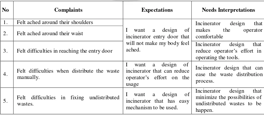
Operator’s needs that have already defined before then will be categorized into several need hierarchies to identify needs data that possibly broke down into more detailed needs. Those detailed needs will be the parameter for determining the technical characteristics in the next process. The design expected to accommodate all user including extreme user that is the operator of existing incinerator. Need statement that categorized into three needs hierarchy elements can be seen on Table 2.
Table 2 Needs Hierarchy
No Complaints Expectations Needs Interpretations
1. Felt ached around their shoulders
I want a design of incinerator entry door that will not make my body feel ached.
Incinerator design that
makes the operator
comfortable 2. Felt ached around their waist
3. Felt difficulties in reaching the entry door
Incinerator design that incinerator that can reduce operator’s effort on the usage
Incinerator design that can ease the waste distribution process.
R
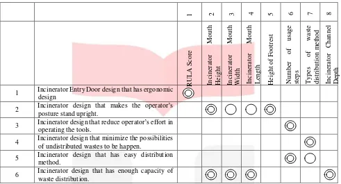
the relationship between the operator’s needs and what technical specifications needed for developing detail design of Incinerator. The specification will provide range of value for determining the final specification of the product [2]. The matrix contains technical characteristics that obtained from translation of needs attributes that have already defined before. The list of technical characteristic can be seen on Table 3.
Table 3 Need Matrix
1 Incinerator Entry Door design that has ergonomic design
2 Incinerator design that makes the operator’s posture stand upright.
3 Incinerator design that reduce operator’s effort in operating the tools.
4 Incinerator design that minimize the possibilities of undistributed wastes to be happen.
5 Incinerator design that has easy distribution method.
6 Incinerator design that has enough capacity of waste distribution.
The specification that obtained from the previous research generated from several resources. The incinerator mouth height gained from the elbow height of Asian anthropometrical data in 50th percentile that valued between 85- 101 cm [3].
Table 4 Specification
No. Technical Characteristic Units Value
1 RULA Score Score 1-4
2 Incinerator mouth height Centimeter 85 – 101 cm
3 Incinerator mouth width Centimeter 32.72
4 Incinerator mouth length Centimeter 33.16
5 Number of usage steps Step(s) Step(s)
6 Types of waste distribution method List List
7 Incinerator Channel Depth Centimeter 35
8 Incinerator Channel Length Centimeter 90
After considering the specification that related to each need statement, define the components contained in the incinerator and its function. After that several alternatives generated for each components and each alternatives will be combined and it has 144 concept combinations. In the table below is the result of feasible concept that can be applied. The generated concept for every components is shown in table 4 and after that it will be reduced
Table 5 Combination table
Alt.
Function
Alternatives 1 Alternatives 2 Alternatives3 Alternatives 4
To push the wastes into the burner Screw Conveyor Push System - -
To move the wastes insertion mechanism Manual Automated - -
To be the channel of waste distribution Box Chamfered Tunnel Inclined Plane
To be the container of the inserted wastes Box Shaft Half Tube -
Table 6 Selected feasible concept
Concept 1 2 3 4 5
A J channel Chamfered Half Tube Screw Conveyor Automated
B J channel Chamfered Half Tube Push System Automated
C J channel Inclined Plane Half Tube Screw Conveyor Automated
D J channel Inclined Plane Half Tube Push System Automated
E U channel Chamfered Half Tube Screw Conveyor Automated
F U channel Chamfered Half Tube Push System Automated
G U channel Inclined Plane Half Tube Screw Conveyor Automated
H U channel Inclined Plane Half Tube Push System Automated
All the feasible concept will be rated in concept screening based on selection criteria to know which is the best concept among the alternatives. Table .. shows the scoring matrix of the feasible alternatives.
Table 7 Concept screening matrix
Selection Criteria
Ref. Concept
A B C D E F G H
Less defect risk
0 + 0 + 0 + 0 + 0
Ease of use
0 + 0 + 0 + 0 + 0
Efficiency 0 + + + + - - - -
Ease of Assembly
0 + + + + - - - -
Sum of + 4 2 4 2 2 0 2 0
Sum of 0 0 2 0 2 0 2 0 2
Sum of - 0 0 0 0 2 2 2 2
Total Score 4 2 4 2 0 -2 0 -2
Rank 1 2 1 2 3 4 3 4
Continue develop the concept?
Combine Combine Combine Combine No No No No
The result of concept screening result shows that there are 4 concept selected to be scored later in concept scoring stage. The four concepts can be combined into two main concept because the combined concept has the same amount of value that if it is combined it will give more value to the customer. The concept combined are chamfered and inclided plane incinerator mouth. Other component concepts adjusted based on the similarities of every concepts. In table 7 shown the calculation in concept scoring matrix that used for choosing the best concept to be developed.
Table 8 Concept screening result
Concept 1 2 3 4 5
A C J channel
Chamfered +
Inclined Plane Half Tube Screw Conveyor Automated
B D J channel
Chamfered +
Table 9 Concept scoring
Selection Criteria Weight
Concept
EG FH
Rate Weighted
Score Rate
Weighted Score Incinerator Entry Door design that has ergonomic
design 10 % 4 0.8 4 0.8
Incinerator Entry Door design that makes the operator stand upright when they are operating the incinerator.
10 % 4 0.8 4 0.8
Incinerator design that reduce operator’s effort in
operating the tools. 20 % 4 0.8 3 0.6
Incinerator design that minimize the possibilities
of undistributed wastes to be happen. 20 % 4 0.8 4 0.8
Incinerator design that has easy distribution
method. 20 % 4 0.8 3 0.6
Incinerator design that has enough capacity of
waste distribution. 20 % 4 0.8 4 0.8
Final Score 4.8 4.4
Ranking 1 2
Continue Yes No
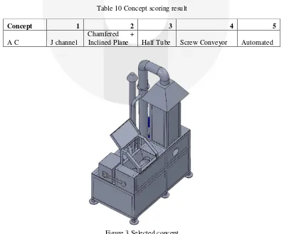
From the calculation of concept scoring matrix, concept that is chosen to be developed is combination of concept E and concept G with combination concept as shown in the table 9. The concept mainly combining automated mechanism of screw conveyor and dedicated mouth shape to avoid the wastes being messed up.
Table 10 Concept scoring result
Concept 1 2 3 4 5
A C J channel
Chamfered +
Inclined Plane Half Tube Screw Conveyor Automated
Figure 3 Selected concept
Table 11 Material list
Components Material
Frame U channel iron (Low Carbon Steel)
Cover Plate Stainless steel plate
Incinerator Mouth Frame U channel iron (Low Carbon Steel)
Screw conveyor Stainless steel plate
Distribution channel Stainless steel plate
4. Results and Analysis 4.1 Finite Element Analysis
The finite element analysis needed for knowing how strong the components can accommodate the load that applied to it. The finite element analysis includes two aspect of measurement that is stress and displacement. Strength is the measurement of how strong the material can hold the load compared to its yield strength. Table 11 shows the result of finite element testing. All of the result of finite element testing shows that the highest force distribution still under the yield strength that make all of the part feasible to be applied based on strength criteria.
Table 12 Finite element stress result
Part Highest Force Distribution Yield Strength
Base Chasis 3.155.555,8 N/m2 248.168.000 N/m2
Bottom Frame 6.148.667,0 N/m2 248.168.000 N/m2
Top Frame 20.572.306,0 N/m2 248.168.000 N/m2
Distribution Channel 1.346.213 N/m2 172.339.008 N/m2
Displacement measurement used for knowing how far the material will be deformed from its initial position. The bigger value of the displacement of the components, the worse material can cold the load. The highest displacement of the components mostly still considered as feasible to be applied.
Table 13 Finite element displacement result
Part Lowest Displacement Highest Displacement
Base Chasis 1 x 10-30 mm 1,379 x 10-2
Bottom Frame 1 x 10-30 mm 9,305 x 10-2
Top Frame 1 x 10-30 mm 2,226 x 10-1
Distribution Channel 1 x 10-30 mm 5,922 x 10-3
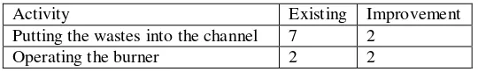
4.2 Ergonomic Analysis Using RULA
Table 14 RULA assessment result
Activity Existing Improvement
Putting the wastes into the channel 7 2
Operating the burner 2 2
Based on the result of RULA assessment, suggested concept of incinerator considered as feasible because the score of improvement design that is 2 considered as ergonomically good [5].
5. Conclusions
From data processing, data analysis, and suggestion that has already developed, has generated some conclusions that referring to the objectives to solve the problems defined in problems identification about this research. The conclusions are :
1. The existing design of incinerator made the operator doing awkward position while operating the incinerator because based on ergonomic standard, the design of the existing incinerator is not ergonomically accepted. The height of existing incinerator entry door that
2. are 169 cm considered as not ergonomic because it makes the operator lift their hand and elbow higher that shoulder position repetitively for 4 hours. This problem can be improved by reducing the height of incinerator mouth to 101 cm perpendicularly from floor.
3. Another disadvantages of existing design of Incinerator entry door is making the operator put high effort to distribute the waste by pushing the mechanism manually. This problem has already solved by replacing the manual mechanism using screw conveyor that automatically drived my mechanical motor.
4. Effectivity of burning process increased by using automated screw conveyor. This kind of mechanism distribute small amount of waste continuously that makes the burning process will spread thoroughly to the wastes because distribution of big amout of waste will make the burning process not spread well.
6. Suggestions
6.1 Suggestions for Company
The company can apply the suggestion for Incinerator for daily operation in waste processing located at Bandung Techno Park (Telkom Education Complex) as the solution for minimizing operator doing awkward position.
6.2 Suggestions for Further Research
Next researcher can develop more comprehensive design in order to complete all aspects for designing complete incinerator. The design hopefully not only considering about human aspects but also the effectivity of components and also burning process. The next research also expected can consider mor aspects about business factor that also can benefit the company in terms of financial aspects.
References
[1] Bandungtechnopark.com (BTP, 2015)
[2] Ulrich, K. T., and Eppinger, S. D. 2012. Product Design and Development 5th Edition. New York: McGraw-Hill Education
[3] Ayoub MM. 1973. Work Place design and posture. Human Factors, 15:265-268 [4] Bridger, R. S. (1995). Introduction to Ergonomics. Singapore: McGraw-Hill