MODIFICATION OF DIESEL ENGINE
TO PRODUCER GAS ENGINE
Nay Zar Aung
Assistant Lecturer, Yangon Technological University, Myanmar.
Master Student at Dept. of Mech. Engineering, Institut Teknologi Sepuluh Nopember, Surabaya, Indonesia Email: [email protected], [email protected]
ABSTRACT
This paper describes considerations and procedure of conversion from diesel engine to producer gas engine. In this paper, the performance of producer gas engine is compared to the original diesel engine and the factors affecting on performance of the producer gas engine are mentioned. After converting the 26.5 kW diesel engines to producer gas engine, the power output of producer gas engine is 40% less than that of original diesel engine. However producer gas engines are used for saving fuel cost and more economic for long time span. The comparison based on 8 kW electricity output that running for 4 hours in a day found that fuel cost for producer gas engine is Ks (Kyats) 2167 and the fuel cost for diesel engine is Ks.(Kyats) 7680, this means save cost of Ks (Kyats) 2008960 along the engine life span.
Key words: Gas engine, Diesel engine, Fuel saving cost
ABSTRAK
Makalah ini menguraikan pertimbangan dan prosedur konversi mesin diesel menjadi mesin gas dan unjuk kerja mesin gas dibandingkan dengan mesin diesel aslinya. Diuraikan juga faktor yang mempengaruhi unjuk kerjanya. Perubahan ini membuat mesin diesel yang awalnya berkapasitas 26,5 kW menjadi mesin gas yang menghasilkan keluaran 40% lebih kecil dari mesin diesel awal. Namun, mesin gas ini dapat menghemat bahan bakar fosil dan secara ekonomi lebih hemat pada masa pakai yang panjang. Perbandingan biaya pada keluaran listrik sebesar 8 kW yang beroperasi 4 jam perhari mendapatkan bahwa biaya bahan bakar untuk mesin gas adalah Ks (Kyats) 2167 dan untuk mesin diesel adalah Ks (Kyats) 7680, ini berarti penghematan sebesar Ks (Kyats) 2008960 selama umur mesin.
Kata kunci: Mesin gas, Mesin diesel, Penghematan biaya bahan bakar
1. INTRODUCTION
At present fossil fuels are becoming more expensive and less to accessible for energy system. In developing countries it is needed to develop indigenous renewable energy sources which can make significant contribution to the economy. In the rural areas of developing countries, ability to produce small amount of mechanical or electrical power utilizing locally available renewable fuels is extremely valuable almost regardless of efficiency.
of Myanmar for many purposes including electricity production, running rice mails, and running irrigation pumps. The primary goals of this paper are:
1) To be able to convert easily diesel engines to producer gas engines locally in rural areas. 2) To supply mechanical or electrical power for industries and agriculture from bio-mass
energy
3) To fulfill in developing renewable energy technology
2. PRODUCER GAS AS A FUEL
The gas produced from gasification of biomass (e.g. nut shell, coke, wood chip or shaving, rice husk, and other crop residues) is called producer gas. It is a mixture of flammable gases (principally carbon monoxide and hydrogen) and nonflammable gases (mainly nitrogen and carbon dioxide). Gas composition and volume percentages of these constitute are shown in Table 1.
It is widely used in industry because it can be produced from cheap fuel. Because of containing hydrogen, it is also a source material for the manufacturer of synthetic ammonia. It is also used as a fuel mainly in glass furnaces. It also serves as a fuel in gas engines to operate tractors, motor cars and trucks and so on [8].
In most areas of Myanmar, the main agricultural source is rice and rice husk from rice mail is available in everywhere and used as biomass for various thermal applications.
Table 1.Producer gas composition and its constitutes [2,3]
No. Name Gas Composition Volume
Percentage (%)
Density (kg/m3) at 20C and 1 atm
Specific Heat Constant Cp (kJ/kg-K)
1 Methane (CH4) 2-4 0.668 2.2
2 Hydrogen (H2) 10-20 0.0899 1.44
3 Nitrogen (N2) 45-60 1.165 -
4 Carbon dioxide (CO2) 5-15 1.842 -
5 Carbon monoxide(CO) 10-30 1.165 1.05
Table 2. Typical gas composition from gasification of various feedstocks [4]
Feedstock Corncob Camellia Seed husk
Wood Shaving
Wood chip Rice husk
Moisture (%) 10.2 15.75 10.2 13 11.51
Size (mm) 150 20-25 10-30 50-250 5-8
CO2 8.54 7.90 10.5 9.6 13.6
CO 21.86 22.6 23.4 21.1 19.8
H2 12.25 13.01 13.76 12.38 10.2
CH4 1.75 3.7 4.04 2.86 3.1
O2 0.2 2.2 0.4 0.4 1.2
N2 55.4 50.59 47.9 53.39 52.1
Table 3. General properties of producer gas [1,6]
Main Flammable gases CO 10-30 %
CH4 2-4 %
H2 10-20 %,
Stoichiometric air-gas ratio F (A /f ) 1.012 Heating value H.V 4.5- 6 MJ/m3
Octane number O.N >150
Density 1.131 kg/m3 (NTP)
Maximum laminar burning velocity
CO 39.0 cm/s
CH4 33.8 cm/s H2 264.8 cm/s
3. MODIFICATION OF DIESEL ENGINE TO PRODUCER GAS ENGINE
Although producer gas can be used directly in spark ignition engines, modified diesel engines are more preferred compared to spark ignition engines for the reasons:
1) The speed of spark ignition engine is too high and so there is large de-rating when operating on producer gas.
2) Larger power output can be obtained from modified diesel engines compared to original spark ignition engines for the same number of cylinders.
3) Modification can be taken out locally in rural areas with a few labors.
The modification of diesel engine to use with producer gas will involve the following tasks:
1) Reducing compression ratio
In this project to demonstrate modification of diesel engine, a sample of diesel engine is chosen. The original engine model is YSD 2100 produced from YANDOWN CO., LTD.
It is vertical, inline, four-stroke, direct injection, twin cylinders engine. It uses forced water cooling method for cooling system. The engine has following specifications:
No. of cylinders - 2
Bore × Stroke - 100 mm × 118 mm
Combustion chamber type - Direct injection,
- Flat Cylinder Head and W-shape piston
Compression ratio - 18 : 1
Displacement Volume - 1.8535 × 10⁻³ m3
Rated power/ Speed - 26.5 kW (30 hp)/ 2600 rpm Full load fuel consumption - 0.2407 kg/ kWh
Max. Torque - 109 Nm
Net Weight - 230 kg
Overall dimension - 672 mm × 560 mm × 715 mm
Cooling system - Forced water cooling system
3.1.Modification of Piston to Reduce Compression Ratio
The compression ratio of original diesel engine is very high, so it cannot be used directly for spark ignition mode. The mixture of very high temperature and pressure will take pre-ignition that causes knocking. Therefore original compression ratio must be reduced near the range of the spark ignition engine type.
To a certain degree, the higher the compression ratio in an engine, the more power it will develop. In practice, however, the compression ratio of the engine is limited by fuel octane number. High compression ratio with low octane number fuel will tend to knocking. In the recent times, Martin J. and Wauters P [5] indicate an upper limit of compression ratio for charcoal and biomass based producer gas as 14 and 11 respectively. However, there is no presentation of experimental evidence in favor of these results.
Although producer gas engine is type of spark ignition engine, its octane number permits for higher compression ratio than petrol engine. Theoretical compression ratio can be estimated by dividing the octane number by 10 [7].
For octane number of over 150 [8], maximum compression ratio for producer gas engine can be estimated as 15:1. Although this ratio does not cause knocking effect, engine heat load is very high during short running time. Spark plug life is very short. Experimental results shows optimum running condition is obtained at compression of 10:1.
1) cutting out the piston
2) inserting gaskets between piston head and cylinder
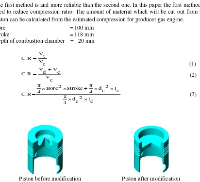
The first method is and more reliable than the second one. In this paper the first method is used to reduce compression ratio. The amount of material which will be cut out from the piston can be calculated from the estimated compression for producer gas engine.
Bore = 100 mm
Fig. 1. Piston shape before and after modification
Sometimes because of error in cutting piston, the compression is slightly higher than Therefore modification of diesel engine involves substitution of ignition system in place of
Piston before modification Piston after modification (2)
fuel injection system in original diesel engine. In this work, battery ignition system is used, which can be classified into two types:
1) Contact (breaker) point type 2) Electric ignition system
In breaker point type system, breaker point gap, rubbing block gap, dwell angle are essential in performance of ignition system. Scale and correct adjustments are required to use that type. In transistorized ignition system, a signal generator is provided in the distributor in place of the cam and breaker point. Therefore to modify the diesel engine, transistorized ignition system is suitable and preferable.
3.2.1. Setting spark plug in place of nozzle
Spark plug size selection depends on the engine power, cylinder size. Cold or hot type of spark plug can be used for the producer gas engine. To set up the spark plug the cylinder head must be drilled along the nozzle hole with a diameter of spark plug as shown in Fig. 2. In modified diesel engines of 18-25 horse power, standard-21 plug is mostly used because its diameter is small and so the space between two valves can be drilled safely.
Fig. 2. Drilling the spark plug at nozzle hole
3.2.2. Setting distributor
Distributor position can be any place where half of the engine is obtained. In one cylinder engine it can be mounted on the original fuel delivery pump shaft with an extension. It also can be mounted on timing gear cover by linking with cam shaft. But mounting distributor on pump shaft is simple and easy way.
The electrode arrangement in the distributor can be considered in accordance with firing interval of the engine. In single cylinder engine, this problem is not occurred and for multi-cylinder engines the arrangement of the electrodes in the distributor is important for spark
14 tpi 1.25 cm drilling tap
timing. In the engines, which have three and ore cylinders, the intervals of electrodes are equal angle of spacing.
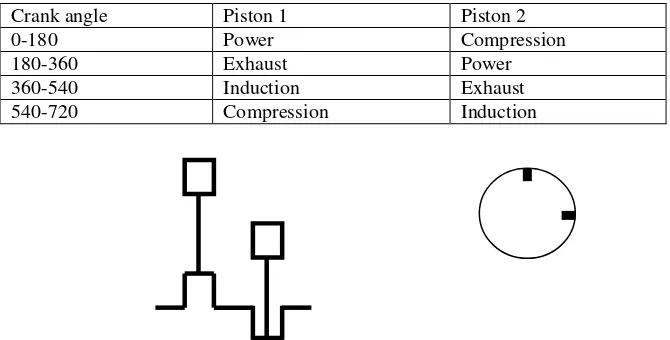
In twin cylinders engines, the electrodes must be carefully arranged. In vertical in-line engines, there are two possible crank shaft shapes as shown in Fig. 3 and Fig. 4.
Ignition timing is an important factor in spark ignition engine. It can vary depending on engine speed, actual fuel-gas composition, and combustion chamber design and fuel octane rating. The results of G Sridhar [9] identify a short range of optimum ignition timing for producer gas engine as in Table 4.
Crank angle Piston 1 Piston 2
0-180 Power Induction
180-360 Exhaust Compression
360-540 Induction Power
540-720 Compression Exhaust
Fig. 3.Electrode arrangement for firing interval 360
Crank angle Piston 1 Piston 2
0-180 Power Compression
180-360 Exhaust Power
360-540 Induction Exhaust
540-720 Compression Induction
Table 4. Optimum ignition timing at various C.R [9]
Range In CR
Ignition Timing, °BTC
17 6 -10 14-15 10-12 12-13 12-14 11-12 15-17 10-11 22-24 8-9 26-28
For producer gas, ignition timing can be more advanced than petrol because it has high octane rating and high flame speed of hydrogen helps the combustion to be at optimal crank angle. Experiments by Middleton and Bruce [6] indicate that, in general, ignition timing should be advanced by 10° - 15°, leading to ignition advances of 35° - 40° before top-dead-centre (TDC). In present work the optimum ignition timing with stable running condition is occurred at 32- 35 BTC.
3.3. Installing Air Gas Mixing Device
When the diesel engines are used on producer gas mode, the air intake region must be modified. An air gas mixer must be provided to generate a suitable air-gas mixture and appropriate air and gas pipes are required to provide correct air-gas ratio and adequate amount of air and gas to the engine. Therefore it is needed to design the air gas mixer based on air fuel ratio and cylinder capacity.
In Myanmar mostly used design of mixing device are simple and easy to fabricate. In these designs the intake is fitted with a gas storage tank in to which the air and gas lines are connected. The air line is opened to the atmosphere through a control valves. The gas from gasifier is also controlled by a valve. For constant speed producer gas engines, hand operated control valves are mostly used. By using hand operated valves, the operator can adjust the mixture to its stoichiometric combustion according to engine condition.
Powe Output Analysis
0 500 1000 1500 2000 2500 3000
Engine speed (r.p.m)
Fig. 5. Air gas mixing device design in Myanmar
4. PERFORMANCE OF PRODUCER GAS ENGINE
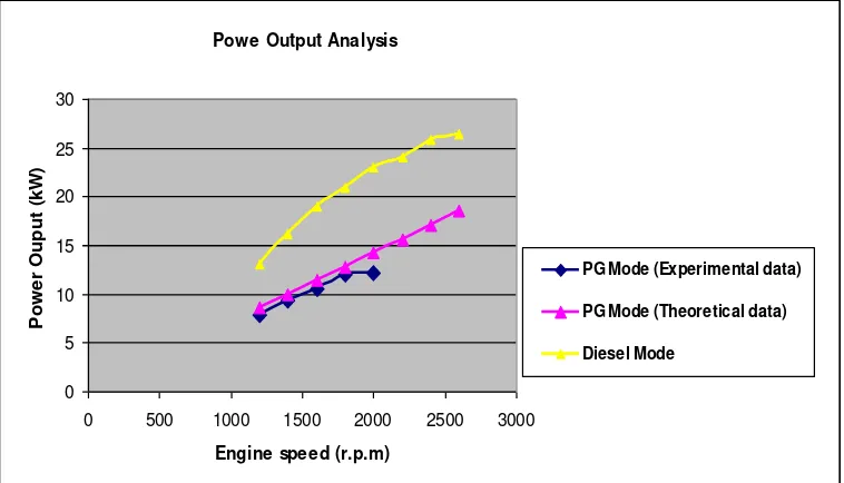
4.1. Power Output
The performance of producer gas engine is be governed by the same factors as for engines operating on liquid fuels.
Fig. 6. Power output comparison of diesel engine and producer gas engine
Gas
Air
(4)
Torque Analysis
0 20 40 60 80 100 120
0 500 1000 1500 2000 2500 3000
Engine Speed (r.p.m)
To
rqu
e
(
N
-m
)
PG Mode
Diesel Mode In this work the engine is connected to 15 kW two phase generator for experiment. At full throttle, zero load condition, the engine can run nearly 2000 rpm.
When the engine is coupled to the generator, at the speed of 1800 the engine can be used for 300 of 40 watt lamps in a village. Therefore at power losses of 40% was occurred. The power output comparison of diesel engine and producer gas engine is shown in Fig. 6.
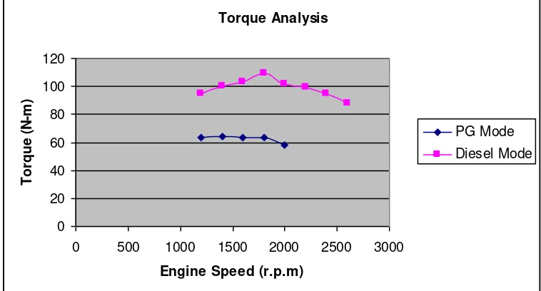
4.2. Torque Output
In diesel mode the maximum torque of 109 N-m was occurred at 1800 rpm. In producer gas engine mode the maximum torque of 64 N-m is at speed of 1400 rpm. These torque results are calculated from engine power outputs.
Fig. 7. Torque output comparison of diesel engine and producer gas engine
4.2.1. Factors affecting on performance of producer gas engine
The root causes of power losses in producer gas engine are: (1) reducing compression ratio,
(2) low heating value of fuel, (3) lower engine speed.
H.V = 12680 VCO + 10800VH2+39500 VCH4 (6)
Air / gas = 2.38 VCO + 2.38 VH2+9.52 VCH4 (7)
pg = 1.842 VCO2 + 1.165 VCO +0.0899 VH2+0.668 VCH4+1.331 VO2
+1.165 VN2 (8)
4.2.2. Economic Comparison of Producer Gas Engine and Diesel Engine
Table 5 shows a comparison between the fuel costs for use rice husk residues and diesel oil for electricity generation for 8 kW. The annual saving on fuel cost is Ks. 2008960 (US$ 1607.17). By deducting the cost of labor, lubricants and spares, the total annual saving with the rice husk gas plant is Ks.1708960 (US$ 1367.17) as compared with the cost of diesel fuel cost.
Total initial investment of gasifier power plant = Ks. 2500000
Labor cost for operation = Ks. 120000/ year
Lubricants and maintenance cost = Ks. 180000/ year
Fuel consumption and fuel costs:
Rice husk consumption = 2 kg/ kWh
Rice husk cost = 34 Ks./kg
Diesel consumption = 0.075 gal/kWh
Diesel cost = 3200 Ks/ gal
From this comparison it can be seen that the total investment of gasifier power plant is recovered during on and half year from fuel saving cost.
5. MAINTENANCE
The operator must maintain the engine as the following procedure to use the engine for long life.
1) After each running period of one week, the cylinder head must be checked to check the sealing and the carbon at the valve head and valve stem is cleaned.
2) After each running period of 300 hours, the ignition timing and rotor and electrodes in the distributor must be checked.
3) After each running period of 2500-3000 hours, each piston is removed to check the wear of piston, ring and piton link because of tar content in the gas.
Table 5.Comparison of fuel cost for 8 kW power plant by using producer gas engine
1) Although producer gas can be used in spark ignition engines directly, a large derating in power is occurred because most spark ignition engine has low compression ratio and high speed. Producer gas can be used at higher compression ratio than petrol and it has lower burning rate which causes the low speed than petrol.
2) For single-cylinder engine, setting ignition system more simple and easier than multi-cylinder engine which needs the distributor. In single-multi-cylinder engine, the signal pickup coil can be set up the fuel delivery pump with an extension.
3) When cutting out the piston material, original depth of combustion chamber should not be changed, because thickness of skirt should not be thinner than original thickness. Therefore only the diameter of combustion chamber is widened in the limit of 1 cm thickness of crown and the piston shape is flat top bowl in piston.
4) Although internal diameter of combustion chamber is widened, the piston surface is not cut to reduce the compression. Therefore the displacement volume of the piston does not change.
5) If the cylinder size is larger than 120 mm, larger size of spark plug should be chosen to spread out sufficient electric charge. Otherwise small size of spark plug is suitable because circumference of drill hole for spark plug should not reach to the water jacket around the valves.
7) In ignition system of producer gas engine has no spark advancer because mostly producer gas engine are used for constant speed and constant load.
8) The volumetric efficiency of producer gas is assumed the same with original diesel engine because these engines have the same displacement volumes and run at same speeds.
9) Producer gas engine produces power 40 % less than original diesel engine. Therefore safety factor should be 0.5 when choosing diesel engine to be modified to run on producer gas mode.
10)For 8 kW power plant running 4 hours in a day, fuel cost for diesel engine is Ks.7680 per day and fuel cost for producer gas engine is Ks.2176. The total investment of 2500000 for gasifier, engine and generator set can be recovered in one and half year.
REFERENCES
[1] Willian Bartok and Adel F. Sarofim, “Fossil Fuel Combustion”, Second Edition, Department of Chemical Engineering, Massachusetts Institute of Technology, Cambridge, 1991.
[2] V Ganesan, “Internal Combustion Engines”, Second edition, Indian Institute of Technology, Madras, 2004.
[3] Cruze, I.E., “Producer Gas from Agricultural Residues - Its Production and Utilization in Internal Combustion Engine”, Quezon City, Philippines, 1983.
[4] Ibrra, E., “Producer Gas Technology for Rural Application”, FAO Agricultural Services Bulettin 62, Philippines, 1984.
[5] Martin J. and Wauters P., “Performance of Charcoal Gas Internal Combustion Engines”, Proceedings of International Conference - New Energy Conversion Technologies and Their Commercialization, Vol. 2, 1981, pp. 1415-1424.
[6] Middleton, F.A. and Bruce, C.S., “Engine Tests with Producer Gas”, Journal of Research of the National Bureau of Standards, U.S.A., 1946.
[7] Fayetee Taylor, C., “The Internal Combustion Engine Theory and Practice”, Cambridge, Massachusetts, 1959.
[8] Grover, P.D., “Biomass”, Thermo-Chemical Characterization for Gasification, Biomass Research Laboratory, Chemical Engineering Department, India Institute of Technology, Delhi, 1989.
[9] G Sridhar, H V Sridhar, S Dasappa, P J Paul, N K S Rajan and H S Mukunda,
![Table 1. Producer gas composition and its constitutes [2,3]](https://thumb-ap.123doks.com/thumbv2/123dok/2614287.1664133/2.612.135.535.438.551/table-producer-gas-composition-and-its-constitutes.webp)
![Table 2. Typical gas composition from gasification of various feedstocks [4]](https://thumb-ap.123doks.com/thumbv2/123dok/2614287.1664133/3.612.142.526.96.216/table-typical-gas-composition-gasification-various-feedstocks.webp)
![Table 4. Optimum ignition timing at various C.R [9]](https://thumb-ap.123doks.com/thumbv2/123dok/2614287.1664133/8.612.266.402.108.212/table-optimum-ignition-timing-various-c-r.webp)