AN ASSESSMENT OF CYLINDER DEACTIVATION SYSTEM APPLIED TO CLOSABLE INTAKE
PORTS IN A SMALL SI ENGINE
MUHAMMAD ARIF BIN DAUD B041010155
BMCA
Email: [email protected]
Draft Final Report Projek Sarjana Muda II
Supervisor: DR. AHMAD KAMAL BIN MAT YAMIN
Faculty of Mechanical Engineering Universiti Teknikal Malaysia Melaka
iv
ABSTRACT
This project is conducted with the main objective of carrying out engine tests to get the
engine performance with and without Cylinder Deactivation System (CDS) that addresses well on
two criteria of the automotive industry, which are low fuel consumption and carbon dioxide
emission during idle condition. The focus of the subject ofthe project is set on gasoline engine,
the more generally used engines for cars in Malaysia. For the purpose of analysis and comparison
of the modified engine model, the PERODUA Myvi 1.3 is made as the benchmark, with the engine
being a 1.3L K3-VE four-stroke four-cylinder gasoline engine. In order to get low fuel consumption,
the author with the advised of the supervisor, has decided to use the cylinder deactivation system.
As to improve the vehicle engine efficiency especially low carbon dioxide emission, the intake
port is closed is seen to be the best solution to prevent the oxygen to enter the intake port. The
period given for the project is for two full semesters. Experiment like carbon dioxide emission test
and vibration test are conducted in order to compare between 4 activated cylinder and 2 deactivated
and I deactivated cylinder cylinder. The best engine performance concept is the 2 deactivated
cylinder with closed intake port which is to have better engine combustion and low carbon dioxide
1
CHAPTER 1
INTRODUCTION
1.0 INTRODUCTION
The project is chosen by the supervisor based on his involvement in the PERODUA Eco-Challenge, a car modification competition for the university. Synchronizing with the competition, the project requires the author to address two main criteria of the automobile industry which are fuel consumption and carbon dioxide emission. The focus of the project is on the city car instead of sports car.
2
However the cylinder deactivation can be embraced in a few distinctive systems. In this project, instead of variable valve timing technology, another approach is adopted by completely close the intake port to prevent the oxygen entering the chamber. This method will affect important criteria regarding λ sensor that trace the oxygen content. The sensor will then send the information to ECU. If the port is not closed, excess oxygen detected by ECU hence more fuel is injected to the port.
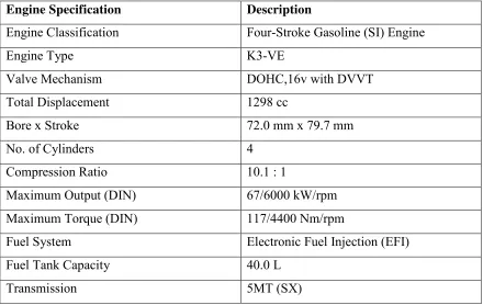
[image:12.612.108.548.360.638.2]This project deals particularly with the car engine itself hence the engine specification are crucial data. The engine chosen for benchmarking is the Myvi 1.3L (manual transmission). The specification of the engine is outlined in Table 1.1.
TABLE 1.1: Engine Specification for PERODUA Myvi
Engine Specification Description
Engine Classification Four-Stroke Gasoline (SI) Engine
Engine Type K3-VE
Valve Mechanism DOHC,16v with DVVT
Total Displacement 1298 cc
Bore x Stroke 72.0 mm x 79.7 mm
No. of Cylinders 4
Compression Ratio 10.1 : 1
Maximum Output (DIN) 67/6000 kW/rpm
Maximum Torque (DIN) 117/4400 Nm/rpm
Fuel System Electronic Fuel Injection (EFI)
Fuel Tank Capacity 40.0 L
3
1.1 PROBLEM STATEMENT
Based on the demand of the project, two essential criteria have to be fulfilled, which are fuel carbon emission and vibration.
1.2 OBJECTIVE
The objective of this project:
1. To assess the carbon dioxide emission for closed intake port based on time
travelled by the engine by cutting off two of selected cylinder.
2. To investigate the vibration level on the engine for the cylinder deactivation system.
1.3 SCOPE
4
CHAPTER 2
LITERATURE REVIEW
2.0 INTRODUCTION
This chapter explains in detail about the existing of a cylinder deactivation system that covers in this report. Basically, most of the existing cylinder deactivation system has a better efficiency compare with other method such as variable valve timing, skipped cycle system, turbocharged, and hybrid car. Due to the increasing of carbon emission on environment and less efficient of spark ignition engine, cylinder deactivation system can give the solution for this problem by reducing the carbon emission and give a better engine performance of the vehicle.
2.1 CYLINDER DEACTIVATION
The previous old days has seen continuously more emission discharge for much essential carbon monoxide, hydrocarbon and nitrogen oxide without the concern of the future. Because of this, many method has been invented in order to reduce the emission levels through decreasing of combustion but actually led to the increasing of the carbon emission levels at the environment. Many said that in the next 20 years, the biggest challenge is to reduce the harmful gas emitted by the combustion. Other than that, the fuel combustion can be minimized because fuel combustion is one of the biggest factor affected the environment.
5
engines. Many technology is found in order to decrease the fuel consumption on the vehicle. They can be classified into 4 components those are first is vehicle efficiency improvement which reduces force output needed to attain the desired vehicle performance, second is a powertrain efficiency improvement which allows the engine to operate in its most efficient region over wider range of vehicle operation, third is engine efficiency improvement which improves the engine internal conversion of fuel to brake torque and forth is energy storages house in which vehicle kinetic energy is converted to a stored and reused to launch or efficiently operate the vehicle. (John Michelini and Chris Glugla, 2003)
In 1981 General Motors were the first to introduce cylinder deactivation with valve shut down in mass production. Whilst this technology was initially mainly reserved to large displacement engines, it has been utilized in the recent past for the entire engine segment. Amongst such uses are also hybrid engines were cylinder deactivation is also used during coast down to minimize cylinder pumping losses and hence to enlarge recuperation. (Flierl et al, 2012)
Cylinder deactivation system is a method to decrease the fuel consumption at part load condition for the spark ignition engine. The fuel consumption can be save at 5 to 10 percent compare with standard engine. The cylinder deactivation system is working only at part load condition means at slow speed. The system is actually skip the cycle of the engine. The combustion cycle is not occur because no ignition and fuel is injected at the deactivated cylinder.
6
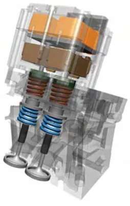
[image:16.612.430.557.71.272.2]
(a) (b)
Figure 2.1:(a) Cylinder deactivation by deactivating the pushrod (source: GM) (b)
Electromechanical valves system concept (source: Valeo)
7
CHAPTER 3
METHODOLOGY
3.0 INTRODUCTION
8
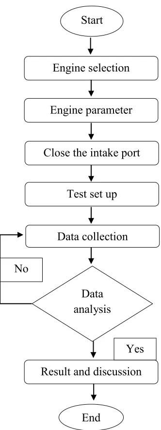
Start
End Engine selection
Engine parameter
Close the intake port
Test set up
Data collection
Result and discussion Data
analysis
[image:18.612.212.378.98.540.2]Yes No
9
3.1 PROJECT EQUIMPENT
Detailed equipment and tasks are listed out for each process of the methodology.
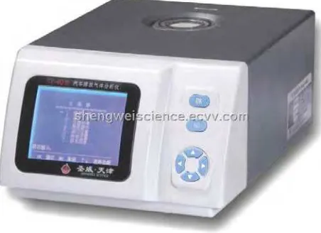
3.1.1 PORTABLE EMISSION ANALYZER
[image:19.612.214.440.402.566.2]The portable emission analyzer is a device to measure carbon dioxide, carbon monoxide, hydrocarbon, carbon dioxide, air-fuel-ratio and lambda. For this project, MEXA-584L has been chosen to measure the carbon dioxide emission in the exhaust pipe. The device has a lightweight and compact with a clear LCD and effortless operation, it can be used as a simple measurement instrument in any work situation. The portable emission analyzer is putted at the exhaust pipe during the experimentation. The data on the LCD cover is recorded every minute of the experimentation. The experiment is repeated by deactivating part of the cylinder. The data recorded will be analyzed.
10
3.1.2 ACCELEROMETER
[image:20.612.191.466.335.543.2]An accelerometer is a device that measures the vibration, or acceleration of motion of a structure. The force caused by vibration or a change in motion (acceleration) causes the mass to “squeeze” the piezoelectric material which produces an electrical change that is proportional to the force exerted upon it. Since the charge is proportional to the force, and the mass is a constant, the charge is also proportional to the acceleration. The accelerometer is putted at the head of the engine during all the experiment. The vibration reading during deactivation system should be higher than during activation system.
11
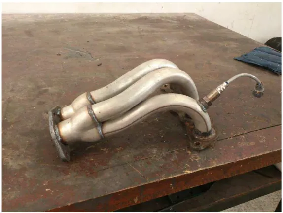
3.1.3 4-2-1 EXHAUST RUNNER
[image:21.612.202.489.233.449.2]A 4-2-1 exhaust runner is refer to the exhaust pipe layout. Four pipes come off the cylinder head (or additional header), which turns into two pipes, and the system finally ends with one pipe leading to the catalytic converter and muffler.
12
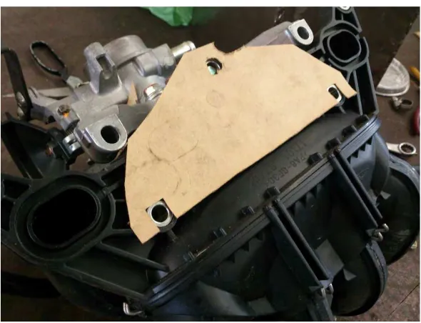
3.1.4 GASKET
[image:22.612.180.475.210.436.2]A gasket is used to prevent air enter the combustion chamber at the selected deactivation cylinder.
13
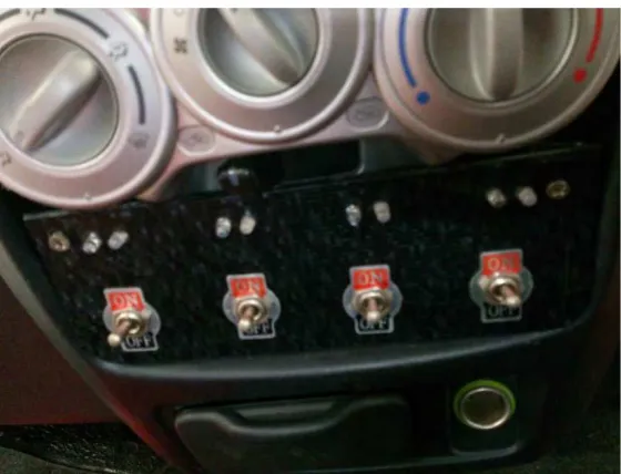
3.1.5 DEACTIVATION CYLINDER SWITCH
[image:23.612.188.468.211.425.2]The cylinder deactivation system consist of four switch. The switch is to cut off the fuel injection and at the same time cut off the spark ignition.
Figure 3.1.5
3.2 TEST SET UP
14
3.2.1 CASE 1
[image:24.612.119.537.192.421.2]The test is set up without any deactivation of the cylinder.
Figure 3.2.1: All the cylinders are activated
3.2.1 CASE 2
The test is set up by closing one intake port