MIRROR IDENTIFICATION AND CORRECTION OF 3D POINT CLOUDS
P.-F. K¨ashammer and A. N¨uchter
Informatics VII – Robotics and Telematics Julius-Maximilians University W¨urzburg, Germany
Commission V, WG V/4
KEY WORDS:mirror identification, jump edge detection, panorama creation, plane detection, 3D point cloud correction
ABSTRACT:
In terrestrial laser scanning (TLS), the surface geometry of objects is scanned by laser beams and recorded digitally. This produces a discrete set of scan points, commonly referred to as a point cloud. The coordinates of the scan points are determined by measuring the angles and the time-of-flight relative to the origin (scanner position). However, if it comes to mirror surfaces laser beams are fully reflected, due to the high reflectivity. Mirrors do not appear in the point cloud at all. Instead, for every reflected beam, a incorrect scan point is created behind the actual mirror plane. Consequently, problems arise in multiple derived application fields such as 3D virtual reconstruction of complex architectures. The paper presents a new approach to automatically detect framed rectangular mirrors with known dimensions and to correct the 3D point cloud, using the calculated mirror plane.
1 INTRODUCTION
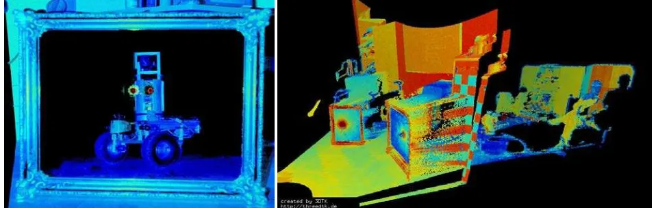
Scanning reflective surfaces with a 3D laser scanner yields incor-rect 3D point clouds, since the emitted laser light is reflected by the surface and a wrong distance is determined. Fig. 1 presents an example, which has won the LiDAR-as-art-contest in 2013. The problem has impact on many post processing steps, e.g., au-tomatic scene modeling and object recognition. In the area of mobile robotics, laser scanners are commonly used for system navigation and robotic mapping or simultaneous localization and mapping (SLAM), i.e., mobile robots have to be able to locate themselves and to identify obstacles. Faulty sensor values of the environment lead to unwanted behavior of the robot and to incon-sistent maps.
The scientific contribution of this paper is the implementation of a new approach of solving this problem for the special case of framed rectangular mirrors whose dimensions are known. Thereby, an identification criterion is created, which allows to break down the problem of mirror detection into several subproblems, which are solved by methods of image processing and mathematics. Up to our knowledge, for the first time, a tool has been created to
Figure 1: Left: The image depicts how our robot Irma3D sees itself in a mirror. The laser looking into itself creates distortions as well as changes in intensity that give the robot a single eye, complete with iris and pupil. Thus, the image is called “Self Portrait with Duckling”. Image courtesy Jan Elseberg. Right: Scanned scene with two mirrors.
identify mirrors in 3D laser scans and to correct the correspond-ing 3D point clouds. Throughout the paper, we will demonstrate the algorithms using 3D data acquired with a pulsed Riegl VZ-400 3D laser scanner in multiple mirror situations. The evalua-tion shows, that the resulting algorithms are applicable without modification to 3D scans acquired using the phase-shift princi-ple. First, we describe the detection of potential mirror contours in a 2D panoramic representation of the point cloud based on a jump edge detection and 3D contour extraction algorithm. Sec-ond, we show how actual mirror contours are identified, how the mirror plain is calculated using the Principal Component Analy-sis (PCA) and also how the point cloud is corrected.
2 RELATED WORK
us-(2010); Klank et al. (2011); Albrecht and Marsland (2013).
3 PANORAMA CREATION
To find potential mirror contours we detect jump edges. First, a 2D panoramic range image of the point cloud is created us-ing the equirectilinear projection method Hamidreza Houshiar and N¨uchter (2013). When creating panorama images from laser scans, each point of the 3D point cloud is projected onto a 2D array of a certain resolution. Therefore the scanned environment of the laser scanner is seen as the projection of a sphere around the scanner. Given the 3D point in spherical coordinates(θ, φ, r)
the projection method determines on which 2D pixel with the co-ordinates(u, v)a 3D point is projected. If multiple 3D points fall into a pixel, e.g., by full-wave-analysis or resolution mismatches, they are stored in a vector. The distancerof one 3D point defines the value of a pixel in the range image version of the equirecti-linear projection. While many projection methods are available ( Hamidreza Houshiar and N¨uchter (2013)) for this work, the pro-jection method equirectangular is used which is defined by the simple projection rule:
u=θ v=φ
with longitudeθand latitudeφ.
Depending on the resolution of the panorama image, multiple points of the point cloud are usually projected on the same pixel
(u, v). If this occurs, there are two possibilities: The map method FARTHEST takes the point with biggest rangeras represented pixel; the map methodNEAREST the one with smallest ranger. Depending on the point cloud and the mirror situation both meth-ods have different effects, so it has to be chosen individually for each scan, cf. Fig 2.
4 JUMP EDGE DETECTION AND CONTOUR EXTRACTION
Jump edges are detected in the panoramic range image and a cor-responding jump edge image of same resolution is created. Be-tween two adjacent pixels of an image, there is a jump edge if the difference in their value is greater than a certain threshold. The sign of the difference describes which of the two pixels is closer to origin, i.e., scanner pose. A jump edge is only represented in the jump edge image, if the considered pixel is closer to origin than the one compared to. This is important so that the detected contour describes only the mirror frame and contains no pixels within the actual mirror plane. Otherwise 3D contours cannot be extracted properly.
Extracting the detected 2D contours of the jump edge image is a known problem of image processing and is done by using the cor-responding OpenCV-functionfindContoursinCvRetrExternal
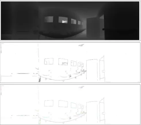
Figure 2: Part of a range image of a mirror. Undefined pixel appear black. Without fillZero-function. Top: Method farthest. Bottom: Method nearest. Not ideal case with 3D points on the mirrors plane.
mode. Subsequently the corresponding 3D contours are extracted by testing which 3D point is projected on the considered 2D con-tour pixel, which is the reverse process of creating the range im-age. Note: The chosen map method changes the outcome of the extracted 3D contour. To get the frame point as 3D contour point, the map method has to benearest.
In the ideal case, all 3D mirror points are laser beam reflection and are therefore further away from the scanner and need to be corrected. However, in some cases 3D points occur that describe the actual mirror surface due to not perfect reflections or detection using the full-wave-analysis, cf. Fig. 2 bottom picture. The 2D contour will then be shifted to the inside of the mirror and will not describe the mirror frame anymore. Consequently, 3D contours might not seem to be connected what leads to the need of filtering these contours or erroneous calculated plane. In those cases the map methodfarthestis chosen to avoid this problem (Fig. 2 top picture).
5 IDENTIFICATION OF MIRROR CONTOURS
So far we describes how potential 2D and corresponding 3D con-tours are extracted. Now the actual mirror concon-tours have to be identified among all detected ones.
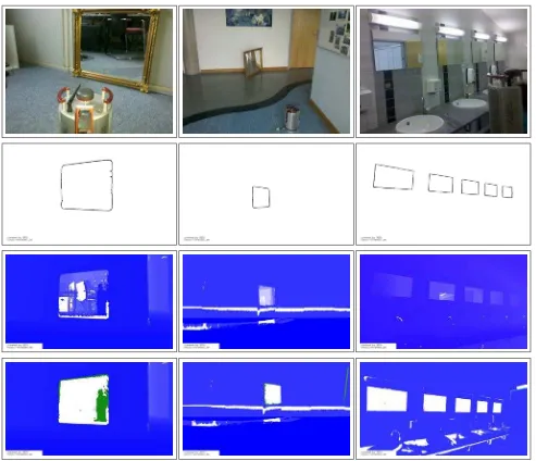
Figure 4: Left: Mirror of size 56×64 cm in an office environment. Middle: Same mirror placed in an office corridor. Right: 5 mirrors of size 40×60 cm in a bath room. Top row: Photo of the scenes. Second row: Extracted 3D contours. Third row: Screenshots in a 3D point cloud viewer without mirror correction. Bottom: Corrected 3D point clouds.
Figure 6: Screenshot of corrected point cloud acquired by Z+F 5006 Scanner in bathroom environment.
increased to not filter the actual mirror contours. Consequently more non-mirror contours pass this filter. In a second step, for all remaining 3D contours, the dimensions as well as the best fit plane through the contour points, which is the mirror plain for a mirror contour, are calculated using the Principal Component Analysis (PCA) Pearson (1901).
In a second filtering process, contours having the specified mirror dimensions within a certain margin of error are identified. For an identified mirror contour, the original point cloud is corrected at hand the corresponding 2D contour as well as the calculated mir-ror plane. To this end, the OpenCV functionpointPolygontest is used to find all 3D points which are projected within the 2D mirror contour. Those are then reprojected on the mirrors plane, stored in a separate 3D point cloud and deleted from the original one.
6 DEALING WITH UNDEFINED PIXEL
There are many challenges in dealing with real-world data. E.g., dealing with undefined pixel in the created panoramic range im-age which originate mainly due to highly reflecting surfaces in the scanned environment, e.g., when scanning water. This means there are pixel in the panoramic image on which no 3D point is projected and therefore do not posses a range value.
Since these undefined pixel cause false jump edges and so creat-ing incorrect contours, a method for dealcreat-ing with those has been developed. Therefore afillZerosfunction assigns values to undefined pixels by copying the closest properly measured pixel from top-left in the 2D image coordinates. This algorithm of-ten leads to shifting of the 2D mirror contour either towards the inside of the mirror or towards the outside. The second case is not a problem because normally the contour will still describe the frame or at least the mirrors plane. In case of a shifting towards the inside, a second algorithm calledfindFramePointfixes this by searching for 3D points which lie in the opposite direction of the mirror contours geometrical mean.
7 EXPERIMENTS AND RESULTS
The mirror identification software is implemented in C/C++ based on the Open Source software3DTK — The 3D Toolkit. Andreas N¨uchter et al. (2015). The software has been tested with a Riegl VZ-400 terrestrial laser scanner and the Zoller+Fr¨ohlich Imager 5006 in the same environment.
For both scanners all mirrors have been identified and thus the corresponding point clouds were corrected. The only case where
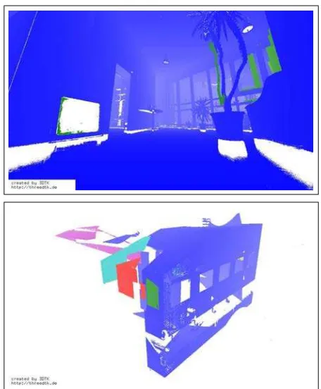
Figure 7: Screenshots of corrected point clouds in a point cloud viewer.
mirrors cannot be identified at all is if mirrors in the panoramic representation are cut of by the panorama frame. This is because the mirror contour cannot be detected as connected in the current software version. In future work, we will mind the scanners start-ing position with respect to the mirror. For all tested point clouds, 3D mirror contour errors are up to 9 cm inxandydimension and up to 3.5 cm inzdimension, which is due to the discretization in-duced by the (relatively low resolution of the) panorama image. There a two main effects that increase the 3D mirror contours and consequently also effect the error of the mirror plane and corrected points. With decreasing incidence angle between laser beams and mirror plane, noise in the extracted frame increases, cf. Figur 5. If mirror plane and laser beams were parallel, the mirror would not appear at all in the point cloud.
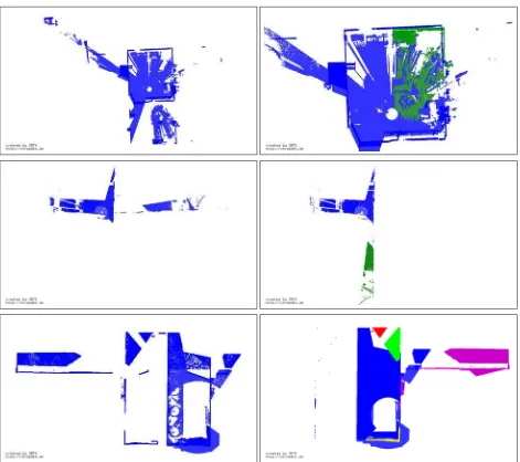
Figure 8 shows the result of the automatic correction on data acquired with a Riegl VZ-400, a plused laser scanner. The top row and bottom row show that the 3D points are projected to the correct location. Figure 7 (bottom) gives a 3D view of the bot-tom row of Figure 8. The remaining misalignment can easily be resolved scan matching methods, such as ICP (iterative closest points). The middle row of Figure 8 demonstrates, how our soft-ware can be used to look around the corner using a mirror.
Figure 8: Screenshots of 3D point clouds in bird eye view. Left: Uncorrected point clouds. Right: Corrected point clouds. Top: Office environment. (Note that right picture is zoomed) Middle: Office corridor. Bottom: Bathroom with 5 mirrors.
8 CONCLUSIONS AND OUTLOOK
This paper describes a complete solution to correct point clouds that contain a mirror of know size. It has been demonstrated to work well in various environments and with pulsed and phse-shift scanners.
Needless to say, a lot of work remains to be done. In future work, will concentrate on arbitrary mirrors, i.e., without knowing the mirror size in advance. Furthermore, we will integrate this tech-nology into our registration and mapping methods and aim to de-velop a method to distingish mirrors from windows. Overall, we aim at reducing the time needed for manually correcting and post-processing of 3D point clouds.
References
Albrecht, S. and Marsland, S., 2013. Seeing the unseen: Simple recon-struction of transparent objects from point cloud data. In: Robots in Clut-ter (RIC) Workshop at Robotics: Science and Systems (RSS ’13), Berlin, Germany.
Andreas N ¨uchter et al., 2015. 3DTK — The 3D Toolkit. http: //slam6d.sourceforge.net/.
Foster, P., Sun, Z., Park, J. J. and Kuipers, B., 2011. Visagge: Visible an-gle grid for glass environments. In: Proceedings of the IEEE International Conference Robotics and Automation (ICRA ’11), Karlsruhe, Germany, pp. 2213–2220.
Hamidreza Houshiar, Dorit Borrmann, J. E. and N ¨uchter, A., 2013. Panorama based point cloud reduction. In: Proceedings of the 16th IEEE International Conference on Advanced Robotics (ICAR ’13), Montev-ideo, Urugauy.
Ihrke, I., Kutulakos, K., Lensch, H., Magnor, M. and Heidrich, W., 2010. Transparent and specular object reconstruction. Computer Graphics Fo-rum 29(8), pp. 2400–2426.
Klank, U., Carton, D. and Beetz, M., 2011. Transparent object detection and reconstruction on a mobile platform. In: Proceedings of the IEEE In-ternational Conference Robotics and Automation (ICRA ’11), Shanghai, China, pp. 5971–5978.
Pearson, K., 1901. On lines and planes of closest fit to a system of points in space. The London, Edinburgh, and Dublin Philosophical Magazine and Journal of Science 6(2), pp. 559–572.
Yang, S.-W. and Wang, C.-C., 2008. Dealing with laser scanner failure: Mirrors and windows. In: IEEE International Conference on Robotics and Automation (ICRA), Pasadena, California.