CORRECTING SPACECRAFT JITTER IN HIRISE IMAGES
S. S. Suttona,∗, A. K. Boyda,b, R. L. Kirkc, D. Cookc, J. W. Backerc, A. Fennemaa, R. Heyda, A. S. McEwena, S. D. Mirchandania
aLunar and Planetary Laboratory, University of Arizona, Tucson, Arizona, USA - (ssutton, audrie, rod, mcewen)@lpl.arizona.edu b
School of Earth and Space Exploration, Arizona State University, Tempe, Arizona USA - [email protected] cAstrogeology Science Center, U. S. Geological Survey, Flagstaff, Arizona, USA - (rkirk, jwbacker)@usgs.gov
WG III/II
KEY WORDS:Spacecraft Motion, Jitter, Pushbroom, Remote Sensing, Mars, HiRISE, Geometric Image Correction.
ABSTRACT:
Mechanical oscillations or vibrations on spacecraft, also called pointing jitter, cause geometric distortions and/or smear in high res-olution digital images acquired from orbit. Geometric distortion is especially a problem with pushbroom type sensors, such as the High Resolution Imaging Science Experiment (HiRISE) instrument on board the Mars Reconnaissance Orbiter (MRO). Geometric distortions occur at a range of frequencies that may not be obvious in the image products, but can cause problems with stereo image correlation in the production of digital elevation models, and in measuring surface changes over time in orthorectified images. The HiRISE focal plane comprises a staggered array of fourteen charge-coupled devices (CCDs) with pixel IFOV of 1 microradian. The high spatial resolution of HiRISE makes it both sensitive to, and an excellent recorder of jitter. We present an algorithm using Fourier analysis to resolve the jitter function for a HiRISE image that is then used to update instrument pointing information to remove geo-metric distortions from the image. Implementation of the jitter analysis and image correction is performed on selected HiRISE images. Resulting corrected images and updated pointing information are made available to the public. Results show marked reduction of geometric distortions. This work has applications to similar cameras operating now, and to the design of future instruments (such as the Europa Imaging System).
1. INTRODUCTION
High resolution imaging from low orbits or low-altitude flybys is achievable with pushbroom imaging. This mode of digital imag-ing builds an image line by line as the camera is flown over the ground target. Multiple detectors can be arranged to increase swath width, accommodate different color filters, or to modify imaging modes within an observation. A significant advantage of pushbroom imaging is the use of time delay and integration (TDI) (McGraw et al., 1980, McGraw et al., 1986) to achieve a useful signal to noise ratio (SNR) in spite of very short line times, without causing excessive smear. The pushbroom method also al-lows for an arbitrary image length to be acquired up to the limits of on board memory capacity or thermal limits. Along with the increasing use of higher resolution imaging comes the issue of sensitivity to platform stability during imaging, especially when using TDI. This paper describes the general problem of space-craft jitter and a specific correction algorithm applied to the High Resolution Imaging Science Experiment (HiRISE) (McEwen et al., 2007) operating on board the Mars Reconnaissance Orbiter (MRO) (Zurek and Smrekar, 2007). As more high-resolution in-struments are flown, the issue of spacecraft jitter will need to be addressed in the design stages as well as during operation, espe-cially for stereo mapping, change detection, high resolution mul-tispectral imaging, or multi-sensor data fusion. The approach de-scribed here has general applicability to similar instruments and image data.
1.1 Background
The small instantaneous field of view (IFOV) of a high-resolution camera operating on an orbiting spacecraft leads to the require-ment for a high degree of stability during imaging. Vibrations
∗Corresponding author
and mechanical motions that are of a frequency comparable to or shorter than the integration time (including TDI) lead to image smear, so the spacecraft must have acceptable stability on these short timescales (∼10 ms for MRO/HiRISE). Lower-frequency
motions with an amplitude comparable to or larger than the IFOV of the detector can cause geometric distortions in the image. Spacecraft jitter is defined here as high frequency periodic mo-tion (Fig. 1), which might not be described by the spacecraft attitude control system. Distortions from jitter in the images are not usually visible to the human eye. However, image process-ing techniques that rely on accurate image correlation, such as change detection and stereo matching, are sensitive to even slight geometric distortions. Jitter also complicates band-to-band color registration, if the color acquisition is not simultaneous.
The presence of spacecraft jitter in orbiting single and multi-CCD pushbroom imaging systems is widely acknowledged, especially as more systems obtain higher spatial resolution (Ayoub et al., 2008, Eastman et al., 2007, Hochman et al., 2004, Kirk et al., 2008, Li et al., 2008, Teshima and Iwasaki, 2008, Theiler et al., 1997). Even sub-pixel distortions can be problematic, as shown in Teshima (2008). The need for correction of spacecraft jitter increases as the number of orbital high resolution pushbroom im-ages increases (Ayoub et al., 2008, Eastman et al., 2007).
of repeat imaging and established ground control. Planetary im-age data does not have the benefit of abundant ground control, and finding an appropriate reference image is not possible most of the time due to the uncertainties in other spacecraft pointing and mapping or vastly differing spatial resolution of the different image data sets.
The approach described here uses Fourier analysis to solve for the absolute spacecraft pointing motion using knowledge of the focal plane layout. All of the jitter information is derived from measuring pixel offsets in the images. The jitter signal measured from the images is analyzed in frequency space. The derived function is compared to the input data to optimize the solution and minimize aliasing. The derived jitter function is ultimately combined with spacecraft pointing data to transform the image pixels to remove distortions in the images. The primary reason this approach to modeling jitter is effective for HiRISE is the very narrow angular separation between overlapping detectors. This results in minimal stereo parallax between detectors.
1.2 HiRISE Instrument Characteristics
The HiRISE instrument consists of a 0.5 m primary mirror along with two smaller mirrors and two fold mirrors (one of which is attached to a focus mechanism), focusing light from the sur-face of Mars onto a staggered array of 14 charge-coupled devices (CCDs), each 2048 pixels wide by 128 TDI stages. The CCDs are arranged on the focal plane assembly with vertical (along track) offsets and horizontal (cross track) overlaps (Fig. 2). The width of an image comprises 10 CCDs spanning the full swath width, collecting visible light in the 550-850 nm range (RED0-9). The center 20% of the swath also has two detectors in the near-infrared, 800-1000 nm, (IR10-11) and two detectors in the 400-600 nm or blue-green (BG12-13) visible wavelengths. Each RED CCD on the HiRISE focal plane overlaps the coverage in the cross track direction of the adjacent CCD by approximately 48 pixels (McEwen et al., 2007).
HiRISE has different imaging modes made up of combinations of TDI with 8, 32, 64, or 128 lines and pixel binning of 1 (unbinned), 2, 4, 8, or 16 for improved SNR (McEwen et al., 2007). Binning and TDI can be set for each CCD. Detector pixels have an IFOV of 1µrad. The nominal spatial scale from the 250 x 320 km or-bit is 0.25-0.32 m/pixel, or slightly lower when pointing off-nadir by up to 30◦. A complete HiRISE observation is made up of the image strips from the ten RED CCDs stitched together, incor-porating the overlapping areas to produce a final full-resolution (unbinned) product that is up to 20,000 pixels wide by an image length, determined by imaging modes and camera memory ca-pacity, typically no more than 120,000 lines (Bergstrom et al., 2004).
1.3 Jitter calibration and mitigation on MRO
HiRISE pointing stability requirements are driven by the line time and number of TDI stages used. Smeared pixels occur when the rate of down track motion does not match the integration time over the TDI stages, or there is cross track motion preventing summation down TDI columns. To avoid smeared pixels, it is essential that the spacecraft remain stable in both the along and cross track directions over the TDI integration timescale. Fre-quency response functions for MRO were modeled and tested on the pre-launch spacecraft configuration for a variety of opera-tional scenarios (Gasparinni, 2005). Although pre-launch mod-eling of spacecraft jitter on MRO was within the requirement of
2.5 pixels within 3-sigma (Gasparinni, 2005), this would have permitted substantial distortion and/or blur. Better performance was (mostly) obtained in flight. Smear of>1/4pixel in HiRISE images due to jitter occurs if the amplitude of motion is greater than 0.25µrad over∼10 milliseconds. Fewer TDI stages can be
used to minimize potential jitter distortions at the cost of SNR (Bergstrom et al., 2004). Mitigating strategies in-flight, such as high-stability mode, greatly reduce but do not eliminate jitter from HiRISE images.
MRO’s onboard pointing information is measured with two star trackers that sample at 10 Hz, and three-laser gyro Inertial Mea-surement Units (IMUs) that sample at 200 Hz (Lee et al., 2003). Spacecraft attitude data from the star trackers and the IMUs are used to create the reconstructed spacecraft pointing kernel (Ac-ton, 1996). There is thought to be some amount of noise or drift in the IMU data which may even introduce other errors into the pointing reconstruction. Therefore is not a reliable source of in-formation for correcting high frequency jitter.
The approach to reducing jitter distortions in HiRISE images pre-sented here is to use the image data, rather than to try to com-pletely eliminate the sources of the motion (which is not possi-ble). The likelihood of inflight jitter was anticipated by the de-signers of the HiRISE focal plane (McEwen et al., 2007). To maximize the jitter information obtainable from the image data, several of the CCDs in one row of the array were shifted off their nominal baseline by a small amount to vary the time separation between adjacent detectors. Although this variation is small, it was expected to be able to prevent aliasing of jitter frequencies to a given time separation, which would prevent detection of those frequencies in the images. The longer time separation between the color (IR and BG) and the RED CCDs expands the data set, and also has the advantage of wider cross-track coverage, rather than the∼48 pixels in the RED-RED pairs. The disadvantage of the IR and BG detectors for measuring jitter is that they usually need to be binned at least 2x2 for adequate SNR.
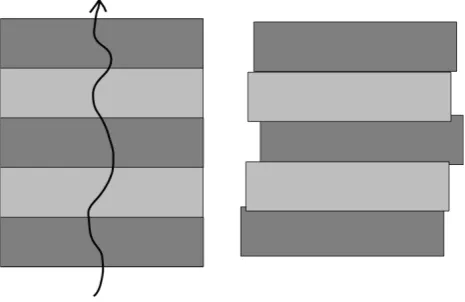
Figure 1. Cartoon illustrating effects of jitter in pushbroom imaging. Left) Camera motion with exaggerated jitter over the ground target. Right) Reconstructed image with jitter distortion.
1.4 Effects Of Jitter In HiRISE Images
Figure 2. HiRISE focal plane layout schematic. Detectors are not shown to scale. The RED detectors are not perfectly aligned
in each of two rows; instead some are slightly offset to mitigate aliasing at higher frequencies. The IR and BG detectors provide
information at lower frequencies.
in HiRISE the distortions in the BG and IR data are measured relative to RED using a grid network of points. The output is a control network that is used to perform a splined interpolation line by line (Becker et al., 2007). This produces satisfactory color registration, but does not remove the geometric distortions in an absolute sense.
Another process affected negatively by jitter is Digital Terrain Model (DTM) production. HiRISE DTMs, at 1 m horizontal res-olution and vertical precision of<1 m, are a high-value derived product. They are used for science as well as mission planning and landing site assessment (Golombek et al., 2012a, Golombek et al., 2012b, Kirk et al., 2008, Kirk et al., 2011). Since the jitter varies from image to image, producing a DTM with a HiRISE stereo pair is complicated by geometric distortions. These distor-tions can introduce significant artifacts to the DTM, or altogether prevent derivation of a good solution for a terrain model. In stereo analysis, two images of the same ground target are acquired from different viewing angles, differing enough to be able to derive heights from the parallax in the two images. The two images are initially tied together using feature matching tie points and control points. They are then transformed to epipolar space, so that parallax is ideally only in the x direction. Cross track dis-tortions cause errors in the x-parallax between the two stereo im-ages, which results in incorrect elevation estimation. In the case of line scan cameras, if this motion is periodic it can result in a ripple pattern parallel to the cross track direction in the terrain model (Kirk et al., 2003). Jitter in the along track direction cre-ates high frequency mismatches in the y-direction, which are very difficult to remove in the triangulation, or bundle adjustment pro-cess. Distortion in the along track direction degrades the results in area matching algorithms, resulting in noisy terrain, spurious matches (blunders) and artifacts in the terrain model. The discon-tinuities along the seams of the RED CCDs also result in linear elevation artifacts of typically 1+m in HiRISE DTMs. It is im-portant to remember that artifacts that appear in DTMs due to jitter are a result of the combined effects of jitter, if present, in either or both of the stereo images. Rather than trying to remove these distortions from the DTM post-production (the only option available to (Kirk et al., 2003) with Mars Orbital Camera (MOC) images), we use the procedure described here to minimize jitter distortions in the source image data. The negative effects of jitter on DTM production and change detection (using orthorectified images) motivates the need for an absolute jitter correction rithm that is general enough to be largely automated. The algo-rithm to derive the jitter in an absolute sense, followed by image correction, is described in the following sections.
2. METHODS
Observations of the measured jitter signal in HiRISE images re-veal that there is no predictable, regular or repeatable pattern. The motions appear to be quasi-periodic, which leads us to take the approach of solving for the frequencies of absolute motions using Fourier analysis. This novel approach allows the pointing history of HiRISE to be modeled more accurately than what is provided by the spacecraft ephemeris. The updated pointing his-tory is then used to project the images, minimizing distortions caused by jitter.
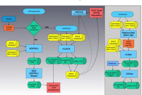
The three stages of our algorithm are detailed in the following sections. We rely on the freely available Integrated Software for Imagers and Spectrometers, v.3.x (ISIS33) (Anderson et al., 2004) to gather these data, as well as for many other steps in the process. Each of these stages is part of a data processing subsys-tem called HiPrecision implemented at the HiRISE Operations Center (HiROC). HiPrecision is a two-branch software process-ing subsystem implemented at HiROC (Fig. 3). The HiRISE Jitter-analyzed CK (HiJACK) branch, applies the methods de-scribed here to correct geometric distortions in HiRISE images. The NoProj branch performs geometric correction only, without modeling and correcting for jitter, as not all HiRISE images re-quire jitter correction. The term ‘kernels’ refers to data files in the formats developed by NASA’s Navigation and Ancillary Informa-tion Facility (NAIF), which provides a data archive of spacecraft and planetary ephemerides, navigation geometry and instrument orientation data, or SPICE (http://naif.jpl.nasa.gov/naif/). In par-ticular, kernel files containing instrument position and pointing information are called camera kernels (CK). These products are freely available through NASA’s Planetary Data System (PDS) Geosciences, Imaging, and Navigation Nodes.
Figure 3. HiPrecision processing subsystem flowchart showing the two branches that produce the NoProj, geometrically corrected products, and the HiJACK branch that additionally performs jitter correction. The HiJACK branch is detailed in the
right panel. Calibrated products are pulled from intermediate steps in the HiRISE image processing pipeline.
2.1 Jitter Measurement
along track spacing (time differences) between the CCDs on the focal plane is taken into account when considering the pixel off-sets. The image data analyzed are a set of CCD image strips that all overlap a common CCD (e.g. RED3-4, RED4-5 and BG12-RED4, or RED4-5, RED5-6 and IR11-RED5). The image data from each CCD have been geometrically and radiometrically cal-ibrated in the standard HiRISE image processing pipeline (Elia-son et al., 2007, Becker et al., 2007) but have not been map pro-jected. If any of the CCDs have been binned, those image strips are enlarged to match the spatial scale of the lowest binning of the set of CCDs. Color CCDs (IR and BG) are typically binned by a factor of 2 or 4 to increase SNR.
In the ideal case where the spacecraft is entirely stable during imaging, a surface feature imaged in one detector should ap-pear at a predictable corresponding location in the overlapping region of the adjacent detector. Deviations from expected object locations in the overlapping areas of each CCD image strip are measured using the ISIS3 applicationhijitreg, which was created specifically to measure offsets in HiRISE images to aid in color registration. Briefly,hijitregcreates a grid or column of control points, in one image, and performs a search for the corresponding feature in the overlapping image, using a pattern matching algo-rithm. Points are measured every 20 lines, an increment chosen by testing for the best balance between resolving the jitter signa-ture and processing time. Four columns of control points across the color image strips are measured to improve statistics, taking advantage of the fact that the IR and BG CCDs completely over-lap the RED CCDs in the cross track direction. The area based matching algorithm finds a maximum correlation at the subpixel precision within user specified search parameters. This best fit match location is described as a pixel offset in sample (cross track) and line (along track) from the expected location of the feature. When describing jitter in image space, we use the terms sample and line, which correspond to the orbital directions cross track and along track, respectively.
The output ofhijitregis a text file listing the program input pa-rameters and the measured matches, ephemeris times, and match quality statistics for each point successfully measured. The out-put fromhijitregcontains three text files – one for each pair of CCDs, which are the input for the following step.
2.2 Fourier Analysis
The pixel offsets measured byhijitregmust be of high enough density and quality to ensure that the derived solution of the jit-ter motion is reliable. Data sets that contain large gaps or sparse matches will not yield a reliable solution, and are rejected. The coregistration data are somewhat noisy, and can contain spurious matches, especially in areas of the image that are low contrast or contain small scale repeating patterns. Multiple columns of points across the IR/BG-RED image pairs are averaged together across each row. Point offset measurements are filtered with a boxcar median function that rejects any point for which the mag-nitude of the offset is larger than a threshold value from its neigh-bors. For the boxcar filter, the window width is 11 points and the tolerance threshold is 2 pixels. From here onward, sample and line data sets are treated separately. A further filtering step is done to minimize noise. In the frequency domain, a low pass Gaussian filter is used to reduce some of the noise in the data (Fig. 4). A bicubic spline interpolation is performed on each data set to create a uniformly spaced series. This step is necessary because although the data points are sampled at evenly spaced intervals, not all sampled points return a valid offset value.
Figure 4. Detail of plot of original pixel offsets (dots) and smoothed data (solid line) from ESP 019988 1750
RED4-RED5.
We wish to model the pointing offset of the camera j(t)as a function of time, but what is observed is the relative offsetF(t)
between two observations of the same feature in different CCDs, separated by an interval∆tsuch that
F(t) =j(t+ ∆t)−j(t). (1)
The functions F(t)and j(t)can each be represented over the time duration of measured offsets,L, by Fourier series
F(t) = 1
whereN is the number of samples obtained. Because we have resampled the relative jitter measurementsF(t)to the uniform spacingtk=kL/NwhereNis a power of 2, the coefficientsai
andbican be obtained efficiently by use of the Fast Fourier
Trans-form (FFT). The FFT algorithm is used as implemented in MAT-LAB, which uses the FFTW library (http://www.fftw.org/) (Frigo and Johnson, 1998) to compute the Discrete Fourier Transform (DFT). The FFT (Cooley and Tukey, 1965) is appropriate because the data we are working with are sets of discrete samples in the spatial domain. Substituting (2) and (3) into (1), using the angle-sum formulae of trigonometry, and identifying terms results in a set of algebraic relations between the known coefficientsaiand
Equation (2) can then be evaluated by an inverse FFT, yielding the values ofF(t)at the discrete timestk. Note that whenai= 2πn
for any integern, in other words, when there are an integer num-ber of cycles of jitter between measurements, the motion repeats exactly. In this caseai=bi= 0and the coefficients in Eqns. (6)
and (7) are unbounded so thatAiandBicannot be reconstructed.
The matching process is thus “blind” to such frequencies. At frequencies close to these singularities the reconstructed motion will be subject to large roundoff errors. An important special case of this phenomenon isn= 0. Comparison of relative jitter can never constrain the absolute pointing error averaged over the whole image, so that this zero frequency term in the series forj must be supplied by thea prioripointing history provided in the form of the NAIF SPICE C-kernel. To avoid inaccurate recon-struction of the jitter at the other blind or near-blind frequencies, those components that are within a given tolerance range of∆t of a particular CCD pair are set to zero and the overall solution is based on the solutions for the other two CCD pairs rather than all three. To optimize this masking process we do a grid search on the width of the frequency window near each blind frequency that is to be excluded, and pick the width that generates the solution best matching the input jitter-difference observations. Finally, the solution is smoothed with a Gaussian lowpass filter applied in the frequency (Fourier transform) domain. The degree of smooth-ing (i.e., the bandwidth of the filter) is selected by a second grid search to minimize the error in reproducing the jitter differences (Fig. 5).
The output from the above algorithm is a text file that describes the derived jitter function in terms of pixel offsets and the corre-sponding ephemeris line time, at evenly spaced line intervals. The sample and line jitter functions are described separately. This text file is read into the subsequent step that uses the derived function to transform the images. Additionally, the jitter function can be used to estimate the minimum pixel smear by taking the deriva-tive of the sample jitter function (interpolated) from line to line. Very high frequency jitter that is not measured could add to this minimum smear.
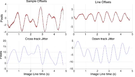
Figure 5. Output of ResolveJitter for PSP 007556 2010. Top row shows sample and line offset data for the RED4-5 pair (red)
with predicted jitter from solution overplotted in black. Bottom row shows the modeled jitter function.
2.3 Image Correction
The ISIS3 applicationhijitterperforms the image transformation. First, the sample and line pixel offsets are converted to rotation angles and combined with the reconstructed MRO pointing infor-mation, as described in the spacecraft observation geometry data,
or SPICE (Acton, 1996). The jitter corrections are applied and used to update the SPICE camera pointing information (stored as a binary large object (BLOB) in the image labels, but ultimately derived from a Camera pointing Kernel (CK) file) before finally projecting all the RED cubes with the ISIS3 applicationnoprojto remove camera distortions.
2.3.1 Convert pixel offsets to angular rotations Hijitter be-gins by converting the line and sample pixel offsets from the jitter text file to rotation angles and later combines them with the re-constructed MRO pointing kernel quaternions. First, the model of feature offsetsj(t), is converted to a model of spacecraft and camera rotation. Because the rotations are small (tens ofµrad at most), the order in which they occur is not significant. We use the Navigation and Ancillary Information Facility (NAIF) (Ac-ton, 1996) routineeul2mto construct a jitter rotation matrix that transforms a vector from the nominal camera coordinates to the true, jittery camera coordinates.
2.3.2 Combine jitter with camera pointing The next step is to combine the jitter matrix with the rotation information recorded in the C-kernel, or CK SPICE blob, to produce an up-dated CK. This is done as a function of time, either at the sam-pling times of the original CK, or if necessary, to incorporate all information in the jitter function, at a higher sampling rate. The CK can be interpolated by using NAIF routines. The jitter func-tionsj(t)are represented by Fourier series and can thus be eval-uated at any time of interest.
Ideally, we would obtain the camera matrix obtained from the CK, which would relate the “nominal” camera pointing to the J2000 inertial coordinate system (M¨uller, 1976, Seidelmann et al., 1980). In reality, there are several problems with simply mul-tiplying the rotations together. First, there are indications that the camera matrix contains high-frequency noise, such as from the IMU data, that does not represent the motions of the camera (nominal, jitter, or otherwise). This noise is excluded from the final rotation matrix by smoothing. Second, the jitter model will be relatively accurate for higher frequencies but may drift over longer periods and depart from the true motion of the camera. Thus, we have a motivation to highpass filter the jitter model in some way. Third, the portions of the frequency domain for which the camera matrix and the jitter vector are valid may overlap, so that the same (non-nominal but real) motions of the camera may be recorded in both datasets. We filter the two datasets in a com-plementary fashion, so that any given frequency of motion is rep-resented by one source, the other, or by a weighted combination that gives the correct amplitude for any frequency that is repre-sented by both.
The desired coordinate system for filtering the camera matrix is defined by a rotation from J2000 to a new system with axes in the spacecraft in-track, cross-track and radial directions, known as the ICR system. The transformation takes a vector (the space-craft position) and transforms it from the J2000 inertial reference frame to the body-fixed reference system relative to Mars, again using NAIF routines.
accurate. The HiRISE ideal camera is a single 20,000-sample line scan camera with no optical distortion and centered in the HiRISE focal plane between RED4 and RED5. When thenoproj’ed im-age strips are mosaicked together, they form a single ideal camera observation. The jitter corrections from the corrected CK are ap-plied to the input pixels to map them to correct positions on the ground. These corrected positions are then mapped to the ideal HiRISE camera with a smoothed CK to produce an image with minimal jitter distortions.
3. RESULTS
There are several ways to assess the quality of the image correc-tion. The ultimate goal of this work is to remove geometric dis-tortions caused by spacecraft motion in all of the HiRISE CCD image strips. If this were to be completely successful, then there would be a) no surface feature mismatches along CCD seams, and b) perfect color registration. Another measure of the quality of the correction can be seen in improvements in the quality of DTMs.
To make a first quality check on the solution, we runhijitregagain on the RED4-RED5 CCDs and compare plots to see if the appar-ent jitter has been removed. Typical results show a substantial reduction in amplitude of the jitter motions, as measured in the CCD-to-CCD pixel offsets withhijitreg(Fig. 6). In most cases, the average amplitude is reduced to< 1pixel. Comparison of the maximum, mean, and standard deviation of the jitter magni-tude, before and after correction, shows that for all cases where the mean is larger than 0.5 pixel, the correction shows a definite improvement, with the mean error being reduced to<0.5pixels (Fig. 7).
Color registration between the IR, BG and RED bands shows im-provement over no correction at all, but in many cases is still not as accurate as the relative correction performed in the HiRISE color processing (Fig. 8). As with the measurements of the jit-ter plots, the color fringing can be seen to be reduced from>1
pixels to∼1 pixel or better.
Qualitatively, improvements can also be seen as a lessening of discontinuities along image strip seams (Fig. 9). Both the re-duction in jitter amplitude and the reduced discontinuities along CCD seams allows for improved stereo analysis resulting in bet-ter DTM quality. In most cases where jitbet-ter correction is applied to stereo pairs, the DTM has fewer artifacts and therefore requires less editing (Fig. 10). Occasionally, there is a jitter frequency that is not corrected, which negatively affects DTM quality, and is not editable.
4. DISCUSSION
It is necessary to combine the jitter reconstruction results with a smoothed version of thea prioripointing. This has to be done at some level because the jitter modeling amounts to integration of a signal that is given in differential form. Thus it very definitely cannot be used to estimate absolute (DC) pointing and it is des-tined to be weak at some range of low frequencies. Our internal analysis of repeat observation coordinates finds better agreement with smoothed pointing kernels (CKs) than with the unsmoothed CKs. However, an analysis of what fraction of information in the standard CKs is useful has not been undertaken. Our results show that combining the jitter reconstruction with the smoothed
Figure 6. Plot ofhijitregresults from ESP 019988 1750 RED4-RED5 before (red) and after (blue) jitter correction.
Figure 7. Comparison of the mean and standard deviation (left) of the jitter magnitude (pixels) before and after correction. Best correction points lie below the 1:1 red diagonal line. For the mean and standard deviation tests, there is improvement for all
cases where the jitter magnitude is>0.5pixels. The max magnitude is not as effective of a measure of the correction due to outliers that do not get filtered out of the measurement routine.
Figure 8. Color registration comparison in detail (zoom level 2:1) of ESP 012039 2010. The black and white arrows point out areas where obvious sample (white arrow) and line (black arrow)
jitter cause color fringing. Left) No color correction shows obvious color fringing from misregistration due to jitter. Center)
Color processed through HiJACK with no other correction shows improved, but not perfect, color registration. Right) Color
processed with a relative correction to the RED band shows good color registration.
Figure 9. Seam (black arrows) between CCD strips in ESP 019988 1750. White arrows indicate places where obvious
features are misaligned in A, and where those feature are now well aligned across the seam in B, which has been processed
through HiJACK.
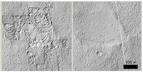
Figure 10. Detail of shaded relief map of a DTM made from ESP 035895 1965 and ESP 036172 1965, which had mean jitter magnitudes of 0.8717 and 0.41184 px, respectively. Left) Shaded relief image of the DTM made with non-jitter corrected images. Artifacts are failures of the stereo correlator due to excessive mismatch between images. Right) The same area of
the DTM produced from jitter corrected images. The “seam” between detectors is quantitatively reduced but does not disappear. Examining elevation profiles across the seam
confirms that the offset is reduced.
make the assumption that the jitter signal is not captured in the CKs because otherwise the jitter would be corrected in the image reconstruction upon applying SPICE data, specifically the recon-structed CKs.
4.1 Improvements to DTM production
Jitter-corrected HiRISE stereo pairs improve stereo correlation in DTM production. The main benefit of jitter correction with HiJACK is the reduction of jitter amplitude, which improves re-sults in stereo matching algorithms. In the worst cases, excessive y-parallax creates blunders in the terrain model which require in-teractive editing. Reduction in jitter also reduces the persistent effect along the CCD strip seams in DTMs. Jitter correction of stereo pairs can reduce the size of these seams from∼5 m to<2
m. In some cases, the jitter correction does not completely elimi-nate jitter issues from stereo images. Based on the results shown in the above section, the color registration of the jitter-corrected color is not perfect, but it is often an improvement over the un-corrected data. Further work needs to be done to develop a robust process to orthorectify color data with jitter-corrected images.
4.2 TDI
The implementation of the algorithm presented here assumes each line in the image is integrated over the programmed line time, without consideration of TDI mode. The effects of TDI should be incorporated into future improvements to the algo-rithm. For example, the centroid of the point spread function varies in a TDI sensor, in the presence of jitter (Hochman et al., 2004).
4.3 Applying Lessons Learned to Future Instrument Design
The jitter correction method described here had not been devel-oped when HiRISE was designed. Without this knowledge, the offsets and overlaps between CCDs are not optimal. Variation of the along-track CCD offsets for some triplets are enough to pro-vide differing frequency information, but timing differences are actually very small compared to the large time difference between the IR/BG and RED CCDs. This creates a range of frequencies that are not well resolved between those two extremes. Future instruments can benefit from this work. In particular there is in-creasing use of larger arrays, which could provide greater flexibil-ity to design for jitter measurement over a broad range of frequen-cies. Future instruments could use complementary metal-oxide semiconductor (CMOS) detectors (also called active pixel sen-sors) that allow for customizing image line spacing to optimize the ability to resolve non-aliased jitter frequencies. For example the Europa Imaging System (EIS) (Turtle et al., 2016) has a wide-angle and a narrow-wide-angle camera, each with 2048 (along-track) x 4096 (cross-track) pixels. With 2048 along-track lines, we can read out multiple line (or digital TDI) sections over a range of pixel separations, to best detect all jitter frequencies. Also, active pixel sensors now provide CCD-level image quality (Janesick et al., 2014), and the independent readout of each pixel allows ad-ditional capabilities. For example, jitter corrections could be ap-plied in the digital processing unit prior to summing lines for TDI, thus minimizing smear. Diagonal TDI is possible if the camera cannot be oriented correctly for TDI (McEwen et al., 2012). The approach presented here can be generalized to other sensors if the parallax angle between overlapping readouts is small. Active pixel sensors have the advantage that this can be selected rather than being built in.
5. CONCLUSION
Results of the jitter correction algorithm and image transforma-tion presented here show a reductransforma-tion of geometric distortransforma-tions in HiRISE images. Despite planning for the effects of spacecraft jit-ter by slightly offsetting detectors on the focal plane, some insen-sitivity to certain frequencies of motion is apparent. Therefore, the overall geometric distortions are minimized, but not com-pletely removed.
REFERENCES
Acton, C., 1996. Ancillary data services of NASA’s Navigation and Ancillary Information Facility.Planetary and Space Science 44(1), pp. 65–70.
Anderson, J., Sides, S. C., Soltesz, D. L., Sucharski, T. L. and Becker, K. J., 2004. Modernization of the Integrated Software for Imagers and Spectrometers. Lunar and Planetary Institute Science Conference35, pp. 2039.
Ayoub, F., Leprince, S., Binet, R., Lewis, K., Aharonson, O. and Avouac, J.-P., 2008. Influence of camera distortions on satellite image restoration and change detection applications.Geoscience and Remote Sensing Symposium, IGARSS, IEEE International pp. 1072–1075.
Becker, K., Anderson, J., Sides, S., Miller, E., Eliason, E. and Keszthelyi, L., 2007. Processing HiRISE images using ISIS3. Lunar and Planetary Institute Science Conference Ab-stractsp. 1779.
Bergstrom, J. W., Delamere, W. A. and McEwen, A. S., 2004. MRO High Resolution Imaging Science Experiment (HiRISE): Instrument test, calibration, and operating constraints. 55th In-ternationall Astronautical Congress, Vancouver, Canada.
Cooley, J. W. and Tukey, J. W., 1965. An algorithm for the machine calculation of complex Fourier series. Mathematics of Computation19, pp. 297–301.
Eastman, R., Le-Moigne, J. and Netanyahu, N., 2007. Research issues in image registration for remote sensing.IEEE Conference on Computer Vision and Pattern Recognitionpp. 1–8.
Eliason, E., Castalia, B., Espinoza, Y., Fennema, A., Heyd, R., Leis, R., McArthur, G., McEwen, A. S., Milazzo, M., Motaze-dian, T., Schaller, C. and Spitale, I., 2007. HiRISE data process-ing and standard data products. Lunar and Planetary Institute Science Conference Abstracts.
Frigo, M. and Johnson, S. G., 1998. FFTW: An adaptive software architecture for the FFT. Proceedings of the International Con-ference on Acoustics, Speech, and Signal Processing3, pp. 1381– 1384.
Gasparinni, T., 2005. Jitter Analysis Summary. Technical report, Lockheed Martin, MRO-FAR-008: Revision 1.
Golombek, M., Bellutta, P., Calef, F., Fergason, R., Hoover, R., Huertas, A., Kipp, D., Kirk, R., Parker, T., Sun, Y. and Sladek, H., 2012a. Surface characteristics and traversability of the Gale crater Mars Science Laboratory landing site. Lunar and Plane-tary Institute Science Conference43, pp. 1608.
Golombek, M., Grant, J., Kipp, D., Vasavada, A., Kirk, R., Fer-gason, R. et al., 2012b. Selection of the Mars Science Laboratory landing site.Space Science Reviews170, pp. 641–737.
Hochman, G., Yitzhaky, Y., Kopeika, N., Lauber, Y., Citroen, M. and Stern, A., 2004. Restoration of images captured by a staggered time delay and integration camera in the presence of mechanical vibrations.Applied Optics43, pp. 4345–4354.
Janesick, J., Elliott, T., Andrews, J., Tower, J., Bell, P., Teruya, A., Kimbrough, J. and Bishop, J., 2014. Mk x Nk gated CMOS imager. In:Proc. SPIE, Vol. 9211, pp. 921106–921106–13.
Kirk, R. L., Howington-Kraus, E., Glauszka, D., Redding, B., Antonsen, J., Coker, K., Foster, E., Hopkins, M., Licht, A., Fen-nema, A., Calef, F., Nuti, S., Parker, T. and Golombek, M., 2011. Wall–to–wall 1–m topographic coverage of the Mars Sci-ence Laboratory candidate landing sites. Lunar and Planetary Institute Science Conference Abstracts42, pp. 2407.
Kirk, R. L., Howington-Kraus, E., Redding, B., Galuszka, D., Hare, T., Archinal, B., Soderblom, L. and Barrett, J., 2003. High-resolution topomapping of candidate MER landing sites with Mars Orbiter Camera narrow-angle images. Journal of Geo-physcial Research108(E12), pp. 8088.
Kirk, R. L., Howington-Kraus, E., Rosiek, M. R., Anderson, J. A., Archinal, B. A., Becker, K. J., Cook, D. A., Galuszka, D. M., Geissler, P. E., Hare, T. M., Holmberg, I. M., Keszthelyi, L. P., Redding, B. L., Delamere, W. A., Gallagher, D., Chapel, J. D., Eliason, E. M., King, R. and McEwen, A. S., 2008. Ultra-high resolution topographic mapping of mars with MRO HiRISE stereo images: Meter–scale slopes of candidate Phoenix landing sites.Journal of Geophysical Research113, pp. E00A24.
Lee, S., Skulsky, J., Chapel, D., Cwynar, R., Gehling, R. and De-lamere, A., 2003. Mars Reconnaissance Orbiter design approach for high-resolution surface imaging.26th Annual AAS Guidance and Control Conference.
Li, R., Di, K., Hwangbo, J. and Chen, Y., 2008. Rigorous photogrammetric processing of HiRISE stereo images and topo-graphic mapping at Mars Exploration Rover landing sites.Lunar and Planetary Institute Science Conferencep. 1864.
McEwen, A. S., Eliason, E., Bergstrom, J., Bridges, N. T., Hansen, C. J., Delamere, W. A., Grant, J. A., Gulick, V. C., Herkenhoff, K. E., Keszthelyi, L., Kirk, R. L., Mellon, M. T., Squyres, S. W., Thomas, N. and Weitz, C. M., 2007. Mars Re-connaissance Orbiter’s High Resolution Imaging Science Exper-iment (HiRISE).Journal of Geophysical Research.
McEwen, A. S., Janesick, J., Elliot, S. T., Turtle, E. P., Stro-hbehn, K. and Adams, E., 2012. Radiation–hard camera for Jupiter system science. International Workshop on Instrumenta-tion for Planetary Missions, held October 10-12, 2012 in Green-belt, Maryland.
McGraw, J., Cawson, M. and Keane, M., 1986. Operation of the CCD/Transit instrument (CTI). Proc. SPIE, Instrumentation in Astronomy VI.
McGraw, J. T., Angel, J. R. P. and Sargen, T. A., 1980. A charge-coupled device (CCD) transit-telescope survey for galactic and extragalactic variability and polarization. SPIE Applications of Digital Image Processing to Astronomy264, pp. 20–28.
M¨uller, E. A. e., 1976. In: Proceedings of the Sixteenth Gen-eral Assembly, Grenoble 1976, Transactions of the International Astronomical Union, Vol. 16.
Seidelmann, P. K., Kaplan, G. H. and Van Flandern, T. C., 1980. New celestial reference system. International Astronomi-cal Union Colloquium56, pp. 305–316.
Teshima, Y. and Iwasaki, A., 2008. Correction of attitude fluctu-ation of Terra spacecraft using ASTER/swir imagery with paral-lax observation. IEEE Transactions on Geoscience and Remote Sensing46, pp. 222–227.
Theiler, J., Henderson, B. and Smith, G., 1997. Algorithms us-ing inter-band cross-correlation for pixel registration and jitter re-construction in mulit-channel push-broom imagers. Proc. SPIE pp. 22–32.
Turtle, E. P., McEwen, A. S., Osterman, S. N., Boldt, J. D., Stro-hbehn, K. and EIS Science Team, 2016. The Europa Imaging System (EIS), a Camera Suite to investigate Europa’s Geology, Ice Shell, and Potential for Current Activity. In: 3rd Interna-tional Workshop on Instrumentation for Planetary Mission, LPI Contributions, Vol. 1980, p. 4091.