www.elsevier.nlrlocaterjappgeo
Ground penetrating radar polarization and scattering
from cylinders
Stanley J. Radzevicius
), Jeffrey J. Daniels
Department of Geological Sciences, The Ohio State UniÕersity, 125 South OÕal Mall, Columbus, OH 43210-1308 USA
Received 18 October 1999; accepted 10 July 2000
Abstract
Ž .
Ground penetrating radar GPR polarization is an important consideration when designing a GPR survey and is useful to constrain the size, shape, orientation, and electrical properties of buried objects. The polarization of the signal measured by the receive antenna is a function of the polarization of the transmit antenna and scattering properties of subsurface targets. Circular cylinders represent important environmental and engineering targets such as buried pipes, wires, and rebar. The backscattered fields from cylinders may be strongly depolarized depending on the orientation of the cylinder relative to the antennas, the electrical properties of the cylinders, and the radius of the cylinder compared to the incident wavelength. These polarization dependent scattering properties have important implications for target detection, survey design, and data interpretation.
As the radius-to-wavelength ratio of metal and plastic pipes decreases, the backscattering properties become more polarization dependent. When using linearly polarized dipole antennas, metallic pipes and low impedance dielectric pipes are best imaged with the long axis of the dipole antennas oriented parallel to the long axis of the pipes. High impedance, dielectric pipes, are best imaged with the long axis of the dipoles oriented orthogonal to the long axis of the pipes.q2000
Elsevier Science B.V. All rights reserved.
Keywords: Ground penetrating radar; Polarization; Cylinders
1. Introduction
Ž .
Ground penetrating radar GPR is a common geophysical technique for investigating the
shal-Ž
low subsurface Annan and Davis, 1989; Ol-hoeft, 1992; Peters et al., 1994; Daniels et al.,
.
1998 . The vector nature of the GPR
electro-)Corresponding author.
E-mail address: [email protected]
ŽS.J. Radzevicius ..
magnetic field, commonly referred to as
polar-Ž
ization, is described Beckman, 1968; Born and
.
Wolf, 1980; Mott, 1986; Balanis, 1989 and is largely ignored by interpreters of GPR data.
Ž .
Investigations by Roberts 1994 and Roberts
Ž .
and Daniels 1996, 1997 have demonstrated the potential of using the polarization characteristics of GPR for defining the size, shape, orientation, and material properties of buried objects.
This paper describes polarization and cylin-der scattering theory and concepts relevant for the GPR practitioner. Analytic solutions and
0926-9851r00r$ - see front matterq2000 Elsevier Science B.V. All rights reserved. Ž .
GPR data examples over buried pipes of vary-ing radii are used to illustrate polarization con-cepts and verify the applicability of theory to commercial dipole antennas and physical mod-els. This manuscript also describes which dipole antenna configurations will result in optimal survey design, depending on whether the targets of interest are metallic or plastic pipes.
2. Polarization
The electromagnetic field at a given point in space, at a given time, has both a magnitude and a direction, and thus is described by vectors. As the electromagnetic wave propagates, the orien-tation and magnitude of these vectors change as a function of time. Polarization describes the magnitude and direction of the electromagnetic field as a function of time and space. When the
Ž
time varying EM fields vary sinusoidally time
.
harmonic , polarization may be classified as linear, circular, or elliptical. If the vector that describes the electric field as a function of time is always directed along a straight line, the field is said to be linearly polarized. If the vector sweeps out a circle, it is referred to as circular polarization. Both are special cases of elliptical polarization, in which the electric field traces out an ellipse. An arbitrary electromagnetic field can be described by three orthogonal basis vec-tors. Since the electric and magnetic fields are orthogonal to the direction of propagation, if we choose one of the basis vectors in the direction of propagation, the electric field can be decom-posed into two orthogonal basis vectors. The electric field of a wave traveling in the z direc-tion can be described by two orthogonal
compo-Ž .
nents as given by Balanis 1989 :
Ex
Ž
z ,t.
sE ex 0 yazcosŽ
vtybzyfx.
and
E
Ž
z ,t.
sE eyazcosŽ
vtybzyf.
Ž .
1y y0 y
where a represents the attenuation constant, b
the phase constant, v the angular frequency, f
the phase, and Ex 0 and Ey 0 are the maximum amplitudes of the E and E components, re-x y
spectively.
2.1. Linear polarization
For a wave to have linear polarization, the time-phase difference between the two compo-nents must be
Dfsfyyfxsnp ns0,1,2,3, . . .
Ž .
22.2. Circular polarization
Circular polarization is achieved only when the magnitudes of the components are the same and the time-phase differences are multiples of
pr2.
where q and y refer to clockwise CW or
Ž .
counterclockwise CCW rotation. ns0, 1, 2, 3, . . .
2.3. Elliptical polarization
Case 2:
Pipes and other objects scatter energy prefer-entially, depending on the incident polarization. The polarization and orientation of the transmit antenna is thus important to ensure sufficient energy is scattered from subsurface targets to allow measurement by the receive antenna. Preferential scattering may result in depolariza-tion of the incident field. Depolarizadepolariza-tion occurs when the amplitude or phase of the incident
Ž Ž ..
field components Eq. 1 are modified such that the scattered field results in a different polarization. The ability of the receive antenna to measure these scattered fields is determined not only by the power of the scattered fields, but also by the polarization match between the scattered fields and the receive antenna. The polarization of the field incident on the receive antenna is determined by the polarization of the field radiated by the transmit antenna and the degree of depolarization experienced by scatter-ing from subsurface objects. It is thus important to understand the polarization properties of GPR antennas and scattering from subsurface objects. Most commercial GPR antennas are dipole or bow-tie antennas that radiate linearly polarized energy with the majority of the radiated electric field oriented along the long axis of the dipole or bow-tie. For a description of dipole fields
Ž .
over a half-space, consult Annan 1973 , Annan
Ž . Ž .
et al. 1975 , Arcone 1995 , Engheta et al.
Ž1982 , Smith. Ž1984. and Radzevicius et al.
Ž2000b . A complete polarization mismatch us-.
ing dipole antennas results when the scattered field and polarization of the receive antenna are
Ž Ž ..
both linearly polarized Eq. 2 and oriented at right angles to each other. For example, rotating ideal dipole antennas orthogonal to each other
Žcrossed-dipoles results in a complete polariza-.
tion mismatch. Spiral, or other circularly
polar-ized antennas, are also used for pipe detection. A complete polarization mismatch using circu-larly polarized antennas results when the scat-tered field and receive antenna are both
circu-Ž Ž ..
larly polarized Eq. 3 , but have electric fields
Ž
with opposite rotation directions left and right
.
circular .
3. Normal incidence plane wave scattering by (
circular cylinders fundamental theory and )
conclusions from analytical solutions
Cylinders represent an important class of ob-jects for GPR since they represent important environmental and engineering targets and also because their scattering properties are strongly polarization dependent. A brief discussion of the importance of polarization on the scattering of plane waves normally incident on both di-electric and conductive circular cylinders is now described. The reader is referred to Balanis
Ž1989 and Ruck et al. 1970 for a more de-. Ž .
tailed explanation of equations and for oblique incidence.
Two linearly independent basis vectors
Žpolarizations. ŽEq. Ž ..1 are necessary to
de-scribe scattering from both dielectric and per-fectly conducting cylinders. It is convenient to choose these polarization vectors such that one vector is oriented along the long axis of the
Ž
cylinder E parallel or transverse-magnetic
ŽTM.. and the other vector oriented orthogonal
Ž
to the long axis of the cylinder E perpendicular
Ž .. Ž .
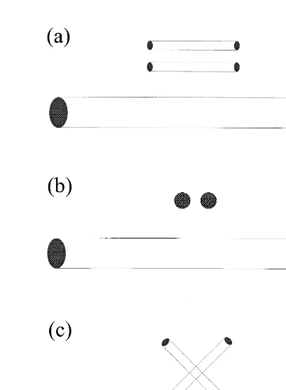
or transverse electric TE Fig. 1 . TM polar-ization is achieved when the long axis of the transmit and receive dipole antennas are ori-ented parallel to the long axis of the cylinder and the survey direction is orthogonal to the
Ž .
long axis of the cylinder Fig. 2a . TE polariza-tion is achieved when both antenna axes are oriented orthogonal to the long axis of the cylin-der and the survey direction is orthogonal to the
Ž .
long axis of the cylinder Fig. 2b .
Ž .
Fig. 1. Definitions of E parallel TM and E perpendicular
ŽTE polarizations relative to a cylinder, as defined in.
Ž .
Balanis 1989 . TM polarization occurs when the electric field is parallel to the long axis of the cylinder. TE polarization occurs when the electric field is perpendicular to the long axis of the cylinder. E and H represent the electric and magnetic fields respectively, while a repre-sents the cylinder radius, b represents the propagation vector,f represents the scattering angle, r represents the radial distance from the cylinder, and x, y, z represent the coordinates of a cartesian coordinate system.
material, the distance from the cylinder, and the scattering angle f, as defined in Fig. 1. A scattering angle of 1808 represents backscatter-ing. Since circular cylinders have a cylindrical shape, their scattering properties are conve-niently described using Hankel and Bessel func-tions because they represent cylindrical waves. Incident and scattered fields for conductive and dielectric cylinders are described in terms of cylindrical coordinates in Appendix A.
Ž .
The radar cross-section RCS represents a convenient way to describe the strength of scat-tered fields observed in the far-field. The RCS is defined as the the area intercepting the amount of power that when scattered isotropically, pro-duces at the receiver a density that is equal to
Ž
the density scattered by the actual target
Bal-.
anis, 1989 .
< s<2 E 2
RCSsrlim 4™` pr < i<2
Ž .
6E
For 2D objects such as an infinite cylinder, the
Ž .
RCS becomes the scattering width SW or
Fig. 2. Examples of GPR surveys using linearly polarized
Ž .
coincident common-offset with small separation antennas to image cylinders. The GPR survey direction is into the
Ž .
page for all the cases. a Dipoles oriented parallel to the long axis of the cylinder are best for imaging conductive and small diameter, low impedance, dielectric cylinders.
Ž .b Dipoles oriented orthogonal to the long axis of the cylinder are best for imaging high impedance dielectric
Ž .
Ž
alternatively the RCS per unit length Balanis,
.
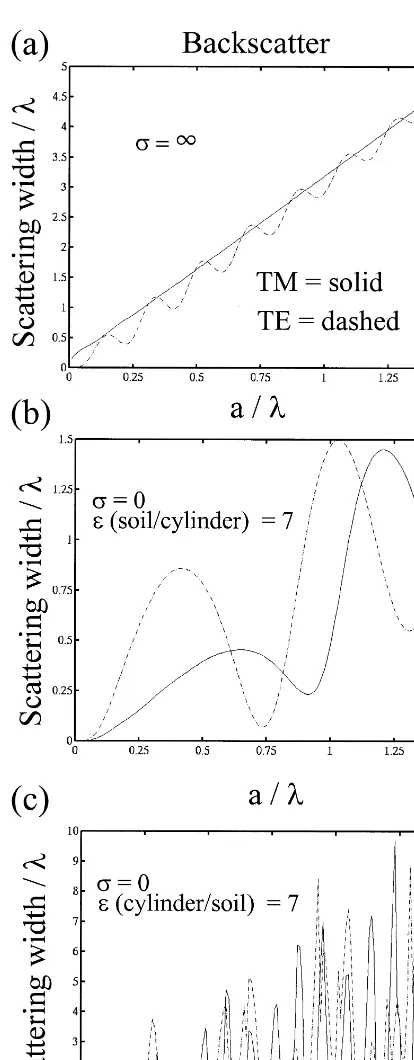
All scattering widths of cylinders in this manuscript are normalized with respect to the wavelength of the incident field and Figs. 3–5 are plots of normalized scattering widths as a function of scattering angle for different radius to incident wavelength ratios. ´ and s will be used to represent dielectric permittivity and con-ductivity.
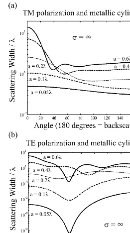
Several universal features are observed in the scattering widths as a function of scattering angle for both conductive and dielectric cylin-ders. As the radius of the cylinder becomes
Ž .
small compared to wavelength: 1 scattering width amplitudes for both polarizations oscillate
Ž .
less, 2 TM polarization scattering widths be-come nearly constant as a function of scattering
Ž .
angle, and 3 TE polarization scattering widths form a single, low amplitude null, at a scattering angle of 908.
Most GPR surveys used to image the subsur-face are conducted in common-offset mode us-ing closely spaced antennas. This results in a
Ž
scattering angle of approximately 1808
back-.
scattered , depending on antenna separation and target depth. It is thus important to further investigate backscattered scattering widths as a function of pipe radius. Fig. 6a represents backscattering from metallic pipes as a function of pipe radius. The TM polarization backscatter-ing width is greater than TE backscatterbackscatter-ing width for most radius-to-wavelength ratios. The TE component oscillates about the TM compo-nent and TE converges toward TM as the radius becomes large compared to wavelength. TM polarization is the preferred polarization for the detection of metallic pipes, as illustrated by Figs. 2a and 6a.
Ž
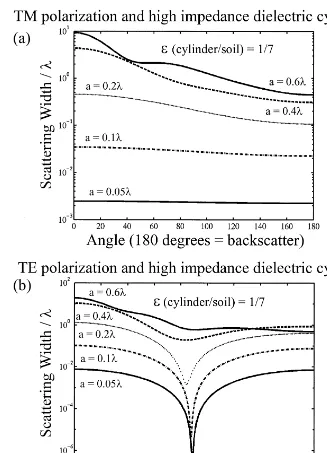
High impedance dielectric cylinders cylin-ders with a permittivity less than the
surround-.
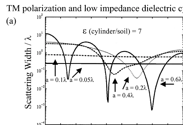
ing soil represent such targets as PVC pipes filled with air or hydrocarbons and surrounded by higher permittivity soil. Fig. 6b is a plot of the backscattering widths for dielectric pipes embedded in a medium having a permittivity seven times greater than the pipe. This repre-sents air filled PVC pipes surrounded by a typical moist sand. The TE polarization backscattering width is greater than the TM backscattering width for small diameter, high impedance, dielectric pipes, and Fig. 2b repre-sents the best survey geometry. Fig. 6c is a plot of backscattering widths for dielectric pipes em-bedded in a medium having a permittivity seven times less than the pipe. The TM polarization backscattering width is greater than the TE backscattering width for small diameter, low impedance, dielectric cylinders, and Fig. 2a rep-resents the best survey geometry. It is often informative to describe scattering by a scatter-ing matrix defined as:
i
where subscripts x and y denote an orthogonal set of coordinates and superscripts i and s de-note the incident and scattered components of the electric E fields, k is the wavenumber, r is the distance from the target to observation point. The scattering matrix is useful in describing
Ž
scattering from thin metal pipes radius small
.
compared to wavelength . The Sx x term domi-nates for thin metal pipes oriented with their long axis of symmetry along the x axis, whereas thin dielectric pipes with an impedance greater than the surrounding soil have Sy y)S .x x
Ž .
Cross-pole antennas Fig. 2c are useful for improving antenna isolation and can be used to reduce clutter under appropriate field conditions and when stratigraphy is not the objective of the
Ž .
Ž .
Fig. 3. Scattering widths for metallic cylinders normalized by the wavelength l of the incident field. As the radius of the cylinder becomes small compared to wavelength, TM scattering widths become nearly constant as a function of scattering angle and TE scattering widths form a single, low amplitude null, at a scattering angle of 908. The TM polarization backscattering widths are greater than the TE polarization scattering widths for most cylinders.
when they scatter electric field components or-thogonal to the field components radiated by the transmit antenna. Scattered cross-components are produced by scattering from rough planes or
Ž
most small objects. Cross-components
compo-.
Ž .
Fig. 4. Scattering widths for high impedance dielectric cylinders, normalized by the wavelength l of the incident field. As the radius of the cylinder becomes small compared to wavelength, TM scattering widths become nearly constant as a function of scattering angle and TE scattering widths form a single, low amplitude null, at a scattering angle of 908. The TE polarization backscattering widths are greater than the TM polarization scattering widths for small diameter cylinders.
Ž . Ž . Ž .
Eqs. 12 – 23 . Balanis 1989 describes the case of a plane wave obliquely incident on both dielectric and conducting cylinders. Balanis ob-served that scattering from a perfectly conduct-ing infinite cylinder does not introduce
Ž .
Fig. 5. Scattering widths for low impedance dielectric cylinders, normalized by the wavelength l of the incident field. As the radius of the cylinder becomes small compared to wavelength, TM scattering widths become nearly constant as a function of scattering angle and TE scattering widths form a single, low amplitude null, at a scattering angle of 908. The TM polarization backscattering widths are greater than the TE polarization scattering widths for small diameter cylinders.
finite length also produce depolarization from edge scattering.
It is not necessary for a target to produce a scattered cross-component to be visible with
cross-pole antennas. A long metallic pipe, while
Ž .
pipes results in field components that are ori-ented both parallel and orthogonal to the long axis of the pipe. The reflected and transmitted
fields for thin pipes are related by the following
Ž .
relationships Daniels et al., 1988 :
yi k r S S
e x x x y
EssEt
ž /
ysinucosuS S
r y x y y
= cosu
Ž .
9sinu
E eyi k r
s
s
ž /
ž
Ž
Sy yySx x.
Et 2 r
=sin2uyS sinx y 2uqS cosy x 2u
/
Ž .
10where Es and and E are the scattered andt
transmitted fields, respectively, and u is the angle between the long axis of the transmit dipole and the long axis of the cylinder. For linear targets Sx y and Sy x are small compared to other components and thus
E eyi k r
s
s
ž /
Ž
Sy yySx x.
sin2uŽ .
11Et 2 r
The ratio EsrE is maximized whent us458for both dielectric and conductive pipes and thus crossed-dipole antennas at 458 with respect to cylinders represent the best antenna geometry to
Ž .
image cylinders Fig. 2c .
4. Linear polarization and scattering from
( )
pipes physical model examples
To test the applicability of the analytical
Ž Ž . Ž . .
solutions Eqs. 12 – 23 and Fig. 6 , data were
Ž .
Fig. 6. Backscattering widths as a function of radius a ,
Ž .
normalized by the wavelength l of the incident field. Solid lines represent TM polarization and dashed lines
Ž .
represent TE polarization. a TM backscattering widths are greater than TE backscattering widths for most metallic
Ž .
cylinders. b TE backscattering widths are greater than TM backscattering widths for small diameter, high
Ž .
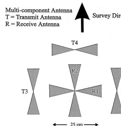
Fig. 7. Geometry of bow-tie antenna elements for 500
Ž .
MHz air multi-component antenna. The antenna consists
Ž .
of four transmitting elements T1, T2, T3, T4 and two
Ž .
receiving elements R1, R2 . The figure is drawn to scale.
recorded in a sand test pit using a Geophysical
Ž .
Survey Systems GSSI bow-tie,
multi-compo-nent antenna having a center frequency of 500
Ž . Ž .
MHz in air Fig. 7 . The antenna consisted of two receiving elements and four transmitting
Ž
elements eight different transmitting–receiving
.
combinations that were used to record the data. Fig. 8 is a plot of the amplitude spectrum obtained by taking the Fourier transform of both co-pole and cross-pole traces with no pipes present. The soil interface influences current distribution and impedance of GPR antennas by an amount determined by the antenna design and the electromagnetic properties of the ground. A soil interface causes the antenna to radiate at
Ž .
lower frequencies 270 MHz peak on interface
Ž .
than in an air whole-space 500 MHz peak . The amplitude spectrum varies smoothly as a
Ž
function of frequency no nulls at a given
fre-.
quency and is approximately Gaussian in shape. A large polarization mismatch with cross-pole
Ž
antennas is observed in Fig. 8 co-pole larger
.
amplitude than cross-pole for all frequencies because each frequency is linearly polarized. Constant polarization for all frequencies is a
Ž
desirable feature of dipole antennas de Jongh et
.
al., 1998 . While time-domain impulse radar
Ž . Ž .
radiates a pulse composed of many frequencies
ŽFig. 8 , the frequencies centered about 270.
MHz have the largest amplitudes and are the most significant for determining the response observed in field data.
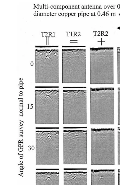
To illustrate the above concepts, data were recorded over plastic and metal pipes with sur-vey directions normal to the long axis of the pipes and at 158, 308, and 458angles to the long axis of the pipes. Long pipes were used to avoid resonance and edge effects. Pipes of varying radii were used to demonstrate the most signifi-cant features observed in the analytic solutions. Fig. 9 shows the results of data recorded over a 0.0032 m radius copper pipe buried at a depth of 0.46 m and having a length of 3.05 m. A soil permittivity probe, described by Caldecott et al.
Ž1985 and operating at 40 and 60 MHz fre-.
quencies gave relative permittivity values of 4 near the surface and graded to a permittivity of 7 at a depth of 0.6 m. The peak 270 MHz frequency has a nominal wavelength of 0.42 m and thus the copper pipe with a radius of 0.0032 m yields a radius-to-wavelength ratio of 0.008. While this radius-to-wavelength ratio is only for a single frequency, most of the energy radiated from the antenna is composed of frequencies that have TM polarization scattering widths greater than TE polarization scattering widths
ŽFigs. 3 and 6a . Fig. 9 demonstrates that this is. Ž .
the case with the TM component T2R1 much
Ž .
greater than the TE component T1R2 .
Cross-Ž .
pole components T2R2 and T3R1 yield maxi-mum values when the dipole antennas are ori-ented at 458 to the long axis of the cylinder, as
Ž . Ž .
described by Eqs. 9 – 11 . No difference be-tween cross-pole configurations would be ex-pected with ideal antennas over homogeneous soils or at a 458survey angle for co-pole config-urations. Coupling between the four transmit-ting elements and two receiving elements, in addition to small construction and alignment differences, results in a slightly different an-tenna response between the two cross-pole
ŽT2R2 and T3R1 and co-pole T2R1 and T1R2. Ž .
configurations. Heterogeneities in the soil also
Fig. 9. GPR survey normal and at 158, 308, 458to the long axis of a copper pipe buried at a depth of 0.46 m, having a radius of 0.0032 m, and a length of 3.05 m. A 270 MHz center frequency antenna on soil with a relative permittiv-ity of 7 has a nominal wavelength of 0.42 m and thus the copper pipe yields a radius-to-wavelength of 0.008. Figs. 3 and 6a suggest that this small radius-to-wavelength ratio
Ž .
results in larger TM scattering widths T2R1 Fig. 7 than
Ž .
TE scattering widths T1R2 Fig. 7 . Cross-pole
compo-Ž .
nents T2R2 and T3R1 yield maximum values when the dipole antennas are oriented at 458 to the long axis of the
Ž . Ž .
pipe as described by Eqs. 9 – 11 .
produce differences due to the antenna element offsets.
having this radius-to-wavelength ratio. In con-trast to the thin metal pipes, Fig. 10
demon-Ž .
strates that the TM polarization T2R1 is only
Ž .
slightly larger than the TE polarization T1R2 , as predicted from analytic solutions. Cross-pole
Ž .
components T2R2 and T3R1 still yield maxi-mum values when the dipole antennas are ori-ented at 458 to the long axis of the metal pipe, as in the thin metallic pipe case. In contrast to
Fig. 10. GPR survey normal and at 158, 308, 458 to the long axis of a steel pipe buried at a depth of 0.61 m, having a radius of 0.0381 m, and a length of 3.66 m. A 270 MHz center frequency antenna yields a nominal radius to wavelength ratio of approximately 0.09. Unlike the thin pipe, Figs. 3 and 6a suggest similar TM and TE scattering widths for metallic pipes having this radius-to-wavelength
Ž .
ratio. In this figure, the TM T2R1 polarization is only
Ž .
slightly brighter than the TE polarization T1R2 , as
pre-Ž .
dicted. Cross-pole components T2R2 and T3R1 still yield maximum values when the dipole antennas are oriented at 458 to the long axis of the pipe, as in the thin pipe case.
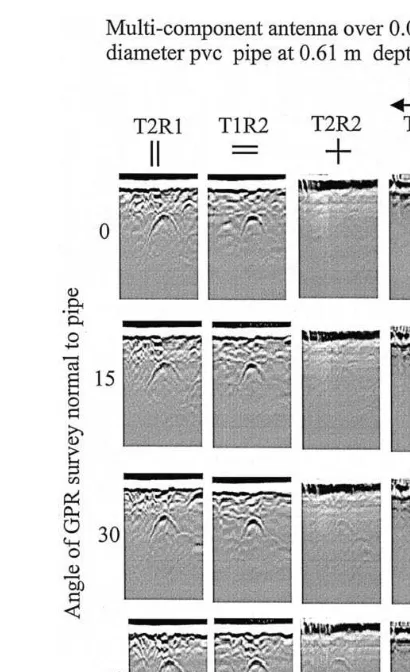
Fig. 11. GPR survey normal and at 158, 308, 458 to the long axis of a PVC pipe buried at a depth of 0.61 m, having a radius of 0.0381 m, and a length of 3.66 m. A 270 MHz center frequency antenna yields a nominal radius to wavelength ratio of approximately 0.09. Figs. 4 and 6b suggest larger backscattering widths for TE compared to TM, given this radius-to-wavelength ratio. This figure verifies that the TE polarization is greater than the TM
Ž .
polarization. Cross-pole components T2R2 and T3R1 still yield maximum values, as in the metallic pipe case, when the crossed-dipole antennas are oriented at 458to the long axis of the pipe.
metal pipes, Fig. 11 demonstrates that the TE
Ž .
polarization T1R2 is larger than the TM
polar-Ž .
ization T2R1 , as predicted from analytic
solu-Ž .
5. Conclusions
The scattering properties of cylinders are strongly polarization dependent. It is thus im-portant to understand the scattering properties of cylinders and the polarization properties of an-tennas used in the GPR survey. Knowledge of the electrical properties of the buried pipe and surrounding soil allows one to constrain the diameter of the pipe. The analytical solutions and field data demonstrate the importance of conducting GPR surveys, with two axially ro-tated measurements to avoid nulls over thin metallic pipes, when using linearly polarized co-pole or cross-pole antennas. An alternative is to use circularly polarized antennas that auto-matically rotate the polarized vector in space and thus removes the direction of signal nulls. As the radius of the metallic pipes increased, the TM and TE polarization backscattering widths become more similar and the need for axially rotated measurments diminished.
When using linearly polarized dipole anten-nas, metallic pipes are best imaged with the long axes of the dipoles oriented parallel to the long axis of the pipe. Small diameter, high impedance, dielectric pipes are best imaged with the dipole axes oriented orthogonal to the long axis of the pipe. Crossed-dipole antennas can be used to reduce clutter and improve antenna isolation when stratigraphy is considered clutter and only pipes or other depolarizing targets are of interest. Maximum amplitudes are observed over pipes when the crossed-dipoles are ori-ented at 458 to the pipe. The best choice of antennas and polarizations for a particular sur-vey depends on the targets of interest and the field conditions.
( )
Appendix A. Cylinder scattering equations
Below are equations, in cylindrical coordi-nates, that describe normally incident plane wave scattering from infinitely long conductive and
dielectric circular cylinders. The scattered field is a function of the electrical properties of the cylinder and surrounding material, the distance from the cylinder, and the scattering angle. Han-kel and Bessel functions represent cylindrical waves and are useful for describing scattering
Ž . Ž .
from cylindrical cylinders. Eqs. 12 – 23
Ž
demonstrate that cross-components components
.
not present in the incident field are not intro-duced by scattering of plane waves normally incident on infinite cylinders. The reader is
Ž . Ž .
referred to Balanis 1989 and Ruck et al. 1970 for a more detailed explaination of equations. TM polarization normally incident on a per-fectly conducting cylinder case:
EisE eyib0x
Ž .
12TE polarization normally incident on a perfectly conducting cylinder case:
TE polarization normally incident on a
dielec-The TE polarization case is expressed in terms of magnetic fields for convenience and one may convert between electric and magnetic fields using Ampere’s and Faraday’s laws. Ei is the
incident field, Es is the scattered electric field,
Hi is the incident magnetic field, Hs is the
scattered magnetic field, r, f, z are the stan-dard coordinates in a cylindrical coordinate sys-tem, r is the radial distance of the observation point, a is the cylinder radius,
xsrcosf
Ž .
24Ž .
Jn br is the Bessel function of the first kind or
XŽ .
order n, Jn br is the derivative of the Bessel
function of the first kind with respect to the entire argument of the Bessel function,
Ž2.Ž .
Hn br is the Hankel function of the second
Ž2.XŽ .
kind of order n, Hn br is the derivative of
the Hankel function of the second kind with respect to the entire argument of the Bessel function, b0 is the phase constant of the mate-rial surrounding the cylinder, b1 is the phase constant of the cylinder, ´r is the ratio of the permittivity of the cylinder to the surrounding material, and mr is the ratio of the permeability of the cylinder to the surrounding material. The eiwt time convention is used in this manuscript.
References
Annan, A.P., 1973. Radio interferometry depth sounding:
Ž .
Part 1. Theoretical discussion. Geophysics 38 3 , 557– 580.
Annan, A.P., Davis, J.L., 1989. Ground-penetrating radar
for high-resolution mapping of soil and rock stratigra-phy. Geophys. Prospecting 37, 531–551.
Annan, A.P., Waller, W.M., Strangway, D.W., Rossiter, J.R., Redman, J.D., Watts, R.D., 1975. The electromag-netic response of a low-loss, 2-layer, dielectric earth for
Ž .
horizontal electric dipole excitation. Geophysics 40 2 , 285–298.
Arcone, S.A., 1995. Numerical studies of the radiation patterns of resistively loaded dipoles. Appl. Geophys. 33, 39–52.
Balanis, C.A., 1989. Advanced Engineering Electromag-netics. Wiley, New York, NY.
Beckman, P., 1968. The Depolarization of Electromagnetic Waves. The Golem Press, Boulder, CO.
Born, M., Wolf, E., 1980. Principles of Optics. Pergamon, New York, NY.
Caldecott, R., Poirier, M., and Svoboda, D.E., 1985. A radio frequency probe to measure soil electrical proper-ties. Final Report 715616-4, US Army Engineer Water-ways Experiment Station Corps of Engineers, P.O. Box 631, Vicksburg, MS 39180.
Daniels, D.J., Gunton, D.J., Scott, H.F., 1988. Introduction
Ž .
to subsurface radar. IEE Proc. F 135 4 , 278–321. Daniels, J.J., Brower, J., Baumgartner, F., 1998. High
resolution GPR at Brookhaven National Laboratory to delineate complex subsurface targets. J. Environ. Eng.
Ž .
Geophys. 3 1 , 1–5.
de Jongh, R.V., Yarovoy, A.G., Ligthart, L.P., Kaploun, I.V., Schukin, A.D., 1998. Design and analysis of new GPR antenna concepts. Proceedings of the Seventh International Conference on Ground Penetrating Radar, May 27–30, Lawrence, KS. pp. 81–86.
Engheta, N., Papas, C.H., Elachi, C., 1982. Radiation patterns of interfacial dipole antennas. Radio Sci. 17, 1557–1566.
Mott, H., 1986. Polarization in Antennas and Radar. Wi-ley, New York, NY.
Olhoeft, G.R., 1992. Geophysical detection of hydrocarbon and organic chemical contamination. Proceedings of the Symposium on the Application of Geophysics to Engi-neering and Environmental Problems: 2, April 26–29, Oak Brook, IL. Society of Engineering and Mining Exploratino Geophysics, Golden, CO, pp. 587–595. Peters, L. Jr., Daniels, J.J., Young, J.D., 1994. Ground
penetrating radar as a subsurface sensing tool. Proc.
Ž .
IEEE 82 12 , 1802–1822, December.
Radzevicius, S.J., Daniels, J.J., Guy, E.D., Vendl, M.A., 2000a. Significance of crossed-dipole antennas for high noise environments. Proceedings of the Symposium on the Application of Geophysics to Engineering and En-vironmental Problems, February 20–24, Arlington, VA. pp. 407–413.
half-space interface. Proceedings of the Eighth Interna-tional Conference on Ground Penetrating Radar, May 23–26, Gold Coast, Australia. pp. 712–717.
Roberts, R.L., 1994. Analysis and theoretical modeling of GPR polarization data. PhD Dissertation, The Ohio State University, Columbus, OH.
Roberts, R.L., Daniels, J.J., 1996. Analysis of GPR
polar-Ž .
ization phenomena. J. Environ. Eng. Geophys. 1 2 , 139–157.
Roberts, R.L., Daniels, J.J., 1997. Modeling Near Field
Ž .
GPR in 3D Using the FDTD Method, 62 4 1114–1126. Ruck, G.T., Barrick, D.E., Stuart, W.D., Krichbaum, C.K., 1970. Radar Cross Section Handbook. Plenum, New York, NY.
Smith, G.S., 1984. Directive properties of antennas for transmission into a material half-space. IEEE Trans.
Ž .