BAB III
1 METODE PENELITIAN 1.1 Prosedur penelitian
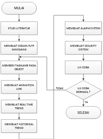
Prosedur dalam melakukan penelitian terdiri dalam beberapa langkah, yaitu langkah pertama melakukan studi literatur dari berbagai sumber terpercaya seperti jurnal internasional, data teknis perusahaan, laporan teknik perusahaan, dll. Langkah kedua yaitu setelah mendapatkan data yang cukup mengenai PLTP Kamojang maka selanjutnya membuat desain SCADA virtual PLTP Kamojang dari flow diagram yang telah ada di PT. Indonesia Power UBP Kamojang dengan menggunakan software Wonderware Intouch 10.0. Langkah ketiga, memberikan
tagname kepada masing-masing object di desain SCADA tersebut. Langkah
keempat yaitu membuat animation link pada setiap object agar ketika di run time
akan terlihat hidup sepertii dengan keadaan real dilapangan.
Setelah membuat animation link, langkah kelima membuat sript real time trend yang menampilkan grafik secara real time. Kemudian langkah keenam
1.2 Flowchart Penelitian
Untuk memudahkan dalam memahami langkah-langkah yang dilakukan penelitian, maka prosedur penelitian tersebut ditunjukkan dalam sebuah flowchart sebagai berikut :
STUDI LITERATUR MULAI
MEMBUAT DESAIN PLTP KAMOJANG
MEMBERI TAGNAME PADA OBJECT
MEMBUAT ANIMATION LINK
MEMBUAT REAL TIME TREND
MEMBUAT HISTORICAL TREND
MEMBUAT SECURITY SYSTEM
MEMBUAT ALARM SYSTEM
UJI COBA
UJI COBA BERHASIL ?
SELESAI TIDAK
YA
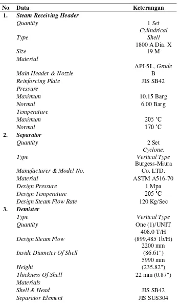
1.3 Data Teknis
Adapun spesifikasi teknis peralatan yang digunakan PLTP kamojang sebagai berikut :
Tabel 1.1 Spesifikasi teknis peralatan PLTP Kamojang
No. Data Keterangan
1. Steam Receiving Header
Quantity 1 Set
Main Header & Nozzle
API-5L, Grade
B
Reinforcing Plate JIS SB42
Pressure
Maximum 10.15 Barg
Normal 6.00 Barg Vertical Type
Manufacturer & Model No.
Burgess-Miura Co. LTD.
Material ASTM A516-70
Design Pressure 1 Mpa
Design Temperature 205 ˚C
Design Steam Flow Rate 120 Kg/Sec
3. Demister
Type Vertical Type
Quantity One (1)/UNIT
Design Steam Flow
408.0 T/H (899,485 1b/H)
Inside Diameter Of Shell
2200 mm (86.61")
Height
5990 mm (235.82")
Thickness Of Shell 22 mm (0.87")
Materials
Shell & Head JIS SB42
Nozzle Neck
JIS STPT38/SB42
Internal
JIS SUS304, JIS SB42
Design Pressure
11 bar.a (11.2 kg/cm2a)
Design Temperature 205 ˚C (401 ˚F)
Normal Operating Pressure
6.5 bar.a (6.6 kg/cm2a)
Normal Operating Temperature
161.9 ˚C (323 ˚F)
Capacity Approx. 19.5 m3
4. Steam Turbine
Type of Turbine
Impulse and reaction double flow condensing
turbine
Number of set Two (2)
Maximum continuous rated output (at
generator terminal) 55,000 kW
Maximum capability (at generator terminal) 57,750 kW
Rated speed at turbine 3,000 rpm
Rotating Direction clockwise
Rated steam pressure at emergency stop
valve inlet 6.5 bar abs
Rated steam temperature at emergency stop
valve inlet 161.9 oC (Sat.)
Design Pressure for MSV and main steam
piping upto MSV 10.15 bar g
Design pressure for GV and steam pipng
upto MSV 7 bar g
Design pressure for steam pipng after GV 6.86 bar g
Design temperature for main steam piping 205 oC
Rated condenser vacum 0.10 bar abs
Number of stages
Double flow of
5 stages Stage inlet pressure
1st stage 6.31 bar abs
2nd stage 2.53 bar abs
3rd stage 0.90 bar abs
4th stage 0.46 bar abs
5th stage 0.24 bar abs
Last stages dimension
Blade height 584.2 mm
Mean diameter 1955.8 mm
1st 1,700 rpm
2nd 3,600 rpm
Inertia moment GD2 including generator 26,700 kg-m2
Barring gear data
Turbin rotor revolution 3 rpm
Driving motor capacity and revolution
5.5 kW x 1,500 rpm
Lifting weight
Upper casing
34,000 kg (including lifting gear)
Rotor
22,000 kg (including lifting gear)
Steam consumption
Output 55,000 kW
Main steam flow 388,300 kg/H
Geothermal gas flow 1,942 kg/H
Steam pressure at main stop valve inlet 6.5 bar abs.
Steam temperature at main stop valve inlet 161.9 °C
Back pressure at exhaust flange 0.10 bar abs.
Power factor 0.80
Max capability
Output 57,750 kW
Power factor 0.84
Steam pressure at main stop valve inlet 6.82 bar abs.
Steam temperature at main stop valve inlet 163.9 °C
Back pressure at exhaust flange 0.104 bar abs
5. Generator
Continuous output at 0.8 pf lagging 68750 kVA
Terminal voltage 11800 kV
Excitation voltage at 0.8 pf lagging 194 V
Excitation current at 0.8 pf lagging 999 A
Excitation voltage on open circuit 54 V
Excitation current on open circuit 344 A
Open circuit transient time constant 7.10 s
Short circuit transient time constant 1.07 s
Efficiency at : Unity p.f Rated p.f
(a) Overloud capability condition (57,75
MW) 98.83% -
(b) Nominal Rating (55 MW) 98.82% 98.47%
(d) 60% (33 MW) 98.45% 98.21%
(e) 40% (22 MW) 97.90% 97.70%
(f) 20% (11 MW) 96.12% 95.98%
(g) 10 % (5.5 MW) 92.67% 92.46%
Reactances : At rated voltage
Deirect axis sub transient 17.30%
Quadrature axis sub transient 17.00%
Direct axis transient 19.00%
Quadrature axis transient 116.50%
Negative sequence 17.20%
Zero sequence 4.90%
Synchronous 208%
Short circuit ratio 0.52
Inertia constant 1.36 kW. s/kVA
Stator
Length of core 2800 mm
Internal diameter of core 970 mm
Air gap 45 mm
Core material
High grade cold rolled silicon
steel pole
Type of slot Open
No. of slot 48
Stator coil slot pitch 19/24
Conductor per slot 2
Type of winding Lap winding
Dimensions of copper forming conductor 2.0 x 10.8
(Strand)
Cross section of one conductor 1193 mm2
Insulation
Class B
Material in slot Mica tape with
epoxy resin
Material on overhang Mica tape with
epoxy resin
Min. Thickness :
to earth 2.55 mm
between turns in slot -
Stator end shield material Silicon steel
pole
Winding capacitance 0.238 µF/phase
Winding resistance 0.00305 Ω/fasa
(75o C)
Rotor
Rotor winding resistance 0.174 Ω (at 75
0
C)
Length of motor body 2825 mm
Length over winding 3729 mm
Length over end ring 3973 mm
Space required for removal Straight :
13,620 mm
45˚ Axis : 8.891 x 4,800 mm
Material of end ring Mn-Cr Alloy
forging
Packing material under end ring
Epoxy glass laminated insulating plate
Length between centre line of bearings 5,800 mm
Diameter of rotor body 880 mm
No. of winding slots 28
Conductor per slot 19
Section of conductor 211 mm2
Slot wedge material Al alloy
Insulation on winding
Epoxy glass laminated insulating plate
Insulation in slot Mica sheet
Minimum thickness :
between turns in slot 0.2 mm
6. Exciter
Exciter rated capacity 250 kW
Exciter speed 3000 rpm
Exciter rated voltage – d.c 240 V
Exciter rated current – d.c 1042 A
Exciter ceiling voltage – d.c no load 440 V
Exciter ceiling voltage – d.c at rated current 440 V
Frequency 200 Hz
Stator insulation class F
Rotor insulation class B
Sailent pole field Yes
Main field resistence at 750 C 5.06 Ω Field current, no load on generator 3.1 A
Field current, MCR load generator 10.2 A
Field time constant 1.3 s
Diode manufacturer Mitsubishi
electric
Diode type Stad
Diode rating DC 240 A/pc
Diode connecting Graze, fullwave
Diode per arm 3
Number of diodes per arm required for
generator 2
Diode protection Fuse
Pilot exciter for brushless exciter
Manufacture Mistubishi
electric
Type PMG
Frequency 300 Hz
Rated capacity 4.75W
7. Transformator
No. Of Phase 3
Rated Frequency (Hz) 50
Normal Voltage 11.8/155
Highest System Voltage (kV) 13.8/170
Continuous Maximum Rating (MVA) 70
Type of Cooling ONAN
Impedance Voltage 13%
Transformator Ratio Control Type On-Load Automatic Range Variation of Ratio
Terminals HV Side LV Side Bushings Bushings
8. Condenser
Type of condenser
Direct contact condenser with spray type main
condensing part and cascade type
gas cooling part
Number of set one (1)
Design vacuum 0.10 bar abs
Kind of cooling water Recirculating water Design cooling water temperature 27 °C
Hot water temperature 42.8 °C
Quantity of cooling water 11,800 m3/hr
Exhaust steam quantity 376,910 kg/hr
Geothermal gas quantity 1,885 kg/hr
Rated steam enthalpy 2,219 kJ/kg
Gas outlet temperature 29 °C
Internal volume of condenser 285 m3
Internal volume of gas cooler 164 m3
Spray nozzle nominal diameter 50 mm
Number of spray nozzle 528 (42 BLIND NOZLLES)
Minimum requaired spray head 2 mAq
Spray water head at cooling water inlet 9.04 mAq
Maximum permissible solid particle size for
nozzle 10 mm
Number of gas cooler tray 3 stages x 2
Maximum permissible solid particle size for
tray 3 mm
Cooling water inlet pipe number 1
size 1,320.8 mm
ø.D. x 8 mmt
Hot water outlet pipe number 2
size 1,524 mm ø.D.
x 10 mmt
9. Main Cooling Water Pump
Fluid
Geothermal Condensate
Water
Temperature 42.8 ˚C (max
70 ˚C)
Minimum NPSH available 5.7 m
Design Discharge Head 32 m (Total Head)
Design Flow Rate 6850 m3/hr
Description
Type of pump
Vertical Pit Barrel type Double Suction
Centrifugal
Number of stages 1
Manufacturer & Model No.
YOSHIKURA KOGYO CO.,
LTD.
Number Suplied 2 x 2 Units
Number Required for Full Duty 2 x 2 Units
Speed 600 rpm
Specific speed 472 rpm
NPSH required 4.0 m
Maximum Total Head A. 39.8 m , B.
40.0 m
Motor Power (rated) 800 kW
Absorbed Power at design conditions 714 kW
Weight :
Pump Approx. 16,500
kg
Motor Approx. 7,000
kg
Baseplate Approx. 2,000
kg
Barrel Approx. 5,200
kg
Materials
Casing
TYPE 316 STAINLESS
STEEL CASING
(SCS14)
Impeller
TYPE 316 STAINLESS
(SCS14)
Shaft
TYPE 316 STAINLESS
STEEL
(SUS316)
Shaft Sleeves
TYPE 316 STAINLESS
STEEL
(SUS316)
Wear Rings
TYPE 316 STAINLESS
STEEL
CARBON & STAINLESS
STEEL
10. Primary Inter Cooler Pump
Duty
Fluid
Geothermal Condensate
Water
Temperature 27 ˚C
Design Discharge Head 30 m (Total Head)
Design Flow Rate 760 m3/hr
Description
Type of Pump
Horizontal Double Station
Centrifugal
Number of Stages 1
Manufacturer & Model No.
YOSHIKURA KOGYO CO.,
LTD./PN8
Number Supplied\ 2 x 2 units
Number Required for Full Duty 2 x 2 units
Speed 750 rpm
Specific Speed 205 rpm
NPSH Required 1.8 m
Maximum Total Head 37 m
Motor Power (rated) 85 kW
Absorbed Power at Design Condition 79.1 kW
Weight :
kg
Motor Approx. 1150
kg
Baseplate Approx. 800 kg
Materials
Casing
TYPE 316 STAINLESS
STEEL CASING
(SCS14)
Impeller
TYPE 316 STAINLESS
STEEL CASING
(SCS14)
Shaft
TYPE 316 STAINLESS
STEEL
(SUS316)
Shaft Sleeves
TYPE 316 STAINLESS
STEEL
(SUS316)
Wear Rings
TYPE 316 STAINLESS
STEEL
CARBON & STAINLESS
STEEL
11. Cooling Tower
Type
Mechanical Induced Draft,
Double-Flow Crossflow
Manufacturer & Model No.
Mitsubishi Heavy Industries LTD.
Water Temperature In 43o C
Water Temperature Out 27o C
Fan Speed 129 rpm
Motor Speed 1000/750 rpm
Power 120 kW/shell
1.4 Software Pendukung