TOWARDS THE IMPLEMENTATION OF SEMI-DYNAMIC DATUM FOR MALAYSIA
N. S. Shariff, J. Gill, Z. M. Amin, K. M. Omar
Faculty of Geoinformation and Real-Estate, Universiti Teknologi Malaysia, 81310 Skudai, Johor – [email protected]
KEY WORDS: Semi-dynamic Datum, Deformation Model, GPS, Seismic Activity
ABSTRACT:
A semi-dynamic datum provides positions with respect to time while taking into account the secular and non-secular deformations, making it the best approach to adapt with the dynamic processes of the earth. Malaysia, as yet, employs a static datum, i.e., GDM2000, at epoch 2000; though Malaysia has evidently been affected by seismic activity for the past decade. Therefore, this paper seeks to propose a design for implementing a semi-dynamic datum for Malaysia. Methodologically, GPS time series analyses are carried out to investigate the seismic activity of Malaysia, which essentially contributes to the proposed design of the semi-dynamic datum for Malaysia. The implications of implementing a semi-dynamic datum for Malaysia are discussed as well. The results indicate that Malaysia undergoes a complex deformation; whereby the earthquakes – primarily the 2004 Sumatra-Andaman, 2005 Nias and 2012 Northern Sumatra earthquakes – have affected the underlying secular velocities of Malaysia. Consequently, from this information, the proposed design, particularly the secular and non-secular deformation models, is described in detail. The proposed semi-dynamic datum comprises a transformation, temporal, and spatial module, and utilizes a bilinear interpolation method. Overall, this paper aims to contribute to the feasibility of a semi-dynamic datum approach for Malaysia.
1. INTRODUCTION
Dynamic processes of the earth are able to displace the land mass of the earth; hence, disrupting any system that requires an ideally non-dynamic platform such as a reference frame. One major dynamic process would be earthquakes that have proven to cause significant displacements to land mass. Two instances are the 9.2 Mw 2004 Sumatra-Andaman earthquake which had caused horizontal surface displacements more than 10 cm, where Phuket, Thailand displaced around 27 cm, while Langkawi displaced 17 cm (Vigny et al., 2005) and the 9.0 Mw 2011 Tohoku-Oki earthquake, combined with the 7.9 Mw aftershock, which produced about 2 m surface displacements in Fukushima and Ibaraki, Japan (Simons et al., 2011).
Consequently, as the surface displaces, the reference frame, or essentially a geodetic datum, is affected as well. When reference stations are dislocated in terms of position, the geodetic datum has to shift to accommodate for the dislocation; thus, providing positions that are up-to-date with respect to surface displacements. The International Terrestrial Reference Frame (ITRF) provides a consistent and up-to-date global geodetic datum. The present ITRF is ITRF2014 which comprises of 1499 stations and realized by a frame of 975 sites (Altamimi et al., 2016). The ITRF updates after a few years (~5 years) to take into account the dislocation of its sites. In other words, the ITRF is updated with regard to the dynamic earth; thus, the ITRF can be essentially called a „dynamic datum‟ (Haasdyk et al., 2014).
A dynamic datum represents a coordinate datum where the coordinates of sites change as a function of time (Tregoning and Jackson, 1999). In the case of ITRF, it is dynamic as its stations‟ coordinates account for the motion of earth‟s tectonic plates, and other deformations of the earth‟s crust, updating every few years (Kelly, 2012). Moreover, the International
GNSS Service (IGS) sites are updated weekly, objectively to remove outliers from the weekly solutions which are finally used in the realization of a new ITRF (Ferland and Piraszewski, 2009; Rebischung et al., 2012). Nonetheless, users are able to download this new coordinate set every week. As a result, regional and national networks are aiming towards implementing a dynamic datum as well; since the ITRF accounts for dynamics at a global scale, it does not accurately represent the local dynamics or local deformation. Therefore, a regional and national geodetic datum will accommodate for local deformations, such as earthquakes, active faults, land subsidence, and so on.
be realized within a particular frame, e.g., ITRF2000 or ITRF2008 (Stanaway et al., 2012). The semi-dynamic datum approach is presently preferred by many countries.
In Malaysia, the geodetic datum currently employed is the Geocentric Datum of Malaysia 2000 (GDM2000), which was officially launched in August 2003 and aligned with ITRF2000 at epoch 2000 (DSMM, 2009). The GDM2000 was realized by the Malaysia Active GPS System (MASS) which is presently superseded by the Malaysia Real-time Kinematic GNSS Network (MyRTKnet). However, the GDM2000 was not earthquakes that occurred in 2004, 2005 and 2007, respectively (DSMM, 2009). Unfortunately, the nationwide adjustment was not implemented as it conflicted with the Malaysian cadastral database, the National Digital Cadastral Database (NDCDB). Hence, a new effort should be proposed in order to solve the issue of GDM2000 by establishing a new reference epoch, aligned with the current ITRF, enabling integration of local surface displacements into the coordinate definition and concurrent with the NDCDB. For further details on the current status of GDM2000, please refer to the paper by Shariff et al. (2014).
As a result, for Malaysia to achieve accurate and reliable positions with respect to time, a semi-dynamic datum approach is recommended. Therefore, the main objective of the paper is to propose a design for implementing a semi-dynamic datum for Malaysia; of which will encompass a time series of selected MyRTKnet station positions from December 2004 to December 2014 representing the seismic activity of Malaysia. The implications of a semi-dynamic datum approach for Malaysia is discussed as well. The seismic activity is a major input as it provides an in-depth understanding for realization of the secular and non-secular deformation models – vital for the development of a deformation model. Overall, the study aims to contribute to the feasibility of a semi-dynamic datum approach for Malaysia.
2. PREVIOUS STUDIES ON THE DEFORMATION OF MALAYSIA
The Sundaland block encompasses a large part of Southeast Asia, of which includes Malaysia. Specifically, Malaysia is located near the core of Sundaland (Simons et al., 2007). In the past, Malaysia was considered to be on a relatively stable continent, where it was far from catastrophic events caused by plate tectonics, specifically earthquakes. However, when the 2004 (9.2 Mw) Sumatra-Andaman earthquake occurred, this fact has changed. After the 2004 Sumatra-Andaman earthquake, the nearest sites from the epicentre showed very large co-seismic displacements: 27 cm in Phuket, Thailand, 17 cm in Langkawi, Malaysia, and 15 cm in Sampali, Indonesia (Vigny et al., 2005).
Furthermore, after the 2004 Sumatra-Andaman earthquake, there have been recurring earthquakes almost every year, the notable ones are [15]: (1) The Nias-Simeulue earthquake on March 28, 2005: epicentre 2.074°N, 97.013°E with a magnitude of 8.6 Mw, (2) The Bengkulu earthquake on September 12, 2007: epicentre 4.520°S, 101.374°E with a magnitude of 8.5 Mw, and (3) The Northern Sumatra earthquake on April 11,
2012: epicentre 2.311°N, 93.063°E with a magnitude of 8.6 Mw. Henceforth, there have been a number of studies regarding the crustal deformation of Malaysia, i.e., mainly DSMM (2009) and Shariff et al. (2014).
The study by Shariff et al. (2014) investigated the deformation in terms of post-seismic motion. The authors found that, the position of the sites displaced with an average magnitude of 25.5 cm from epoch 2000 to epoch 2011 in ITRF2000. This preliminary study processed 2011 MyRTKnet data (1 year) and compared it with the published GDM2000 coordinates at epoch 2000, yet this study does prove that Malaysia is evidently affected by local deformation, i.e., earthquakes, which have caused significant shifts in coordinates.
On the other hand, DSMM (2009) processed data between December 2004 to April 2009, taking into account the 2004, 2005 and 2007 Sumatran earthquakes. DSMM (2009) further reported the co-seismic displacements for the three earthquakes, whereby the 2004 Sumatra-Andaman earthquake ranged between 1.5 to 17 cm, the 2005 Nias earthquake ranged between 1 to 6.5 cm and the 2007 Bengkulu earthquake ranged between 1 to 3 cm. Overall, the displacement between 26 December 2004 to 30 April 2009 is 1 to 25.8 cm, which is similar to the results by Shariff et al. (2014).
The results by DSMM (2009) and Shariff et al. (2014) show that Malaysia has experience a significant amount of displacement. However, the seismic activity of Malaysia after 2011, including the 2012 Northern Sumatra earthquake, has not been studied; thus, providing a further gap for this study. Therefore, as Malaysia is rather frequently affected by earthquakes, especially due to the Sumatran subduction zone, a semi-dynamic approach is the best solution in achieving consistent and accurate positions relative to the dynamic earth.
3. REVIEW ON SEMI-DYNAMIC DATUM APPROACH
A geodetic datum consists of a set of parameters that represents the size and shape of the ellipsoid, and origin, orientation and scale of a coordinate system, where the ellipsoid‟s origin and orientation is with respect to the 3D Cartesian System (Torge, 1980; Drewes, 2009; Jekeli, 2012). A modern geodetic datum, or commonly known as a geocentric datum, adopts an ellipsoid with respect to the Earth-Centre-Earth-Fixed system. The ITRF is the best representation of a global geocentric datum, whereby it is defined by a set of well-defined conventions and parameters. The main advantage of a geocentric datum is that a single homogenous geodetic datum can be realized throughout the world. This means that, at national level, a geocentric datum can be realized by connecting its national reference frame to the subset of geodetic stations, i.e., IGS, of the global reference frame, i.e., ITRF; hence, adopting the ITRF geocentric datum.
Realization of national geocentric datum associates to a reference epoch as well, of which the coordinates refer to a specific epoch. If the coordinates of the geodetic stations are held fixed to that reference epoch, the geocentric datum is called a static datum (Grant and Pearse, 1995). Therefore, the static datum only accurately reflects the actual position, corresponding to the ITRF, on that particular reference epoch. Herewith, the reliability and accuracy of the datum may degrade over time due to earth‟s geological and dynamic processes. As a result, the dynamic datum was developed to accommodate coordinate changes over time. However, as mentioned, the The International Archives of the Photogrammetry, Remote Sensing and Spatial Information Sciences, Volume XLII-4/W5, 2017
GGT 2017, 4 October 2017, Kuala Lumpur, Malaysia
This contribution has been peer-reviewed.
dynamic datum requires the coordinate of geodetic stations to change regularly in an automated manner, either weekly, monthly, or yearly; thus, introducing an array of epochs (Blick and Grant, 1998).
As a dynamic datum may pose practical problems especially at the user level as of now, a hybrid static-dynamic datum, called the semi-dynamic datum, has been implemented in several studies. According to Blick et al. (2009), a semi-dynamic datum is defined as the coordinates of geodetic stations fixed at a reference epoch with the inclusion of a deformation model, of which enables, (1) coordinates to be generated at the reference epoch from observations made at a time other than the reference epoch, and (2) coordinates at a time other than the reference epoch to be generated from the reference epoch coordinates. This definition applies the concept of coordinate propagation between any observation epoch and a reference epoch within the spatial and temporal extent of the deformation model. The deformation model also plays a crucial role to avoid offset between any newly observed coordinates and any existing spatial data described at the reference epoch (Haasdyk et al., 2014). This is especially applicable for absolute positioning
technique, e.g. Precise Point Positioning (PPP), whereby the position results will not conflict when compared to the existing base map after applying a deformation model (Denys et al., 2007).
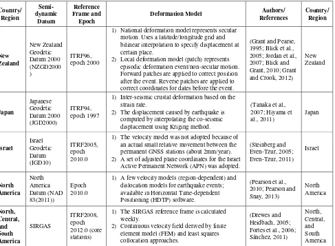
Currently, several countries have implemented the semi-dynamic datum such as New Zealand, Japan, Israel as well as regions such as North America. A summary of the implementation is described in Table 1.
Referring to table 1, New Zealand, Japan, and North America implements a semi-dynamic datum which consists of 2 underlying models within the deformation model: (1) secular deformation model, and (2) a non-secular deformation model, while Israel does not implement the former model. Therefore, there is no standard approach to implement a semi-dynamic datum as it completely depends on the seismic activity of the region, i.e., New Zealand, Japan, and North America undergoes high seismic activity. As a result, there are certain Forward patches are applied to correct position after the event. Reverse patches are applied to correct coordinates for dates before the event.
(Grant and Pearse,
1) Inter-seismic crustal deformation based on the strain rate.
2) The displacement caused by earthquake is computed by interpolating the co-seismic
1) The velocity model was not adopted because of an actual small relative movement between the permanent GNSS stations (about 2mm/year). 2) A set of adjusted plane coordinates for the Israel
Active Permanent Network (APN) was adopted.
1) A few velocity models (region-dependent) and dislocation models for earthquake events;
1) The SIRGAS reference frame is calculated weekly.
2) Continuous velocity field derived by finite element model (FEM) and least squares
Table 1. Implementation of semi-dynamic datum or similar approaches in several countries and regions
3.1 Deformation Model
The deformation model is the fundamental requirement to realize a semi-dynamic datum. Therefore, much care has be taken to realize it. However, in order to produce a reliable deformation model, two underlying models must be developed,
models represent secular „velocities‟ and non-secular „displacements‟. Both these models then contribute to actualizing a deformation model. However, as mentioned, certain considerations need to be taken into account to develop a deformation model for a specific region, i.e., from modelling
of the seismic motion to managing the semi-dynamic datum database. Table 2 summarises these considerations.
Consideration Explanation
Inter-seismic, co-seismic and post-seismic deformation modelling
As mentioned there are two motions that requires to be modelled: secular and non-secular motion. There are many techniques that can be used to model such motions. Secular motions can be modelled using bilinear interpolation method [36], Euler pole definition for the rigid plate (Stanaway et al., 2012), Gridded Absolute Deformation Model (Stanaway et al., 2014), DEFNODE model (Mccaffrey, 2002; Pearson and Snay, 2013) and Strain rates (Tanaka et al., 2007; Hiyama et al., 2011), Finite Element Model and Least Squares Collocation (Drewes and Heidbach, 2005). While non-secular motion can be modelled using a dislocation model of Okada (Okada, 1985), Kriging method (Tanaka et al., 2007; Hiyama et al., 2011; Haasdyk, 2014) and simple plane coordinate adjustments (Steinberg and Even-Tzur, 2005).
Deformation model update rate
The deformation model needs to be updated in two cases: (1) the existing deformation model is unable to predict the current position at certain (~5cm) accuracy level after several years, (2) significant earthquakes, resulting in co-seismic deformations (Blick et al., 2009; Blick and Grant, 2010; Tanaka et al., 2007). The latter is compulsory after an event of an earthquake. However, the former may degrade over time due to errors in the deformation model. According to Blick and Grant (2010), the deformation model has to maintain its accuracy even after 10 years.
Managing changing coordinates within a database
A database management system (DBMS) is required to handle the semi-dynamic datum
coordinate changes. The DBMS with the incorporation of the deformation model will ensure that corrections are applied to coordinates, whether to an epoch before (reverse patch), or after an earthquake (forward patch) (Grant and Crook, 2012). The DBMS basically manages coordinate propagation within the extent of the deformation model, and integration of new patches.
Table 2. Considerations for developing a deformation model
3.2 Issues of a semi-dynamic datum
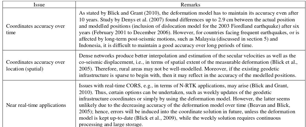
The implementation of a semi-dynamic has its own issues especially in terms of spatial and temporal accuracy, near real-time applications, and the cadastral database. Table 3 briefly explains the main issues with regarding to the implementation of a semi-dynamic datum.
Based on this table, a few matters should be noted. Firstly, in order for Malaysia to implement a semi-dynamic datum, an investigation into the seismic activity is required to choose the best method to realize the secular and non-secular deformation models, as well as a suitable reference epoch for the semi-dynamic datum. Subsequently, the method for implementing the semi-dynamic datum for Malaysia should be designed properly.
Issue Remarks
Coordinates accuracy over time
As stated by Blick and Grant (2010), the deformation model has to maintain its accuracy even after 10 years. Study by Denys et al. (2007) found differences up to 2.9 cm between the actual position and modelled positions (inclusion of dislocation model for the 2003 Fiordland earthquake) after six years (February 2001 to December 2006). However, for countries facing frequent earthquakes, or is affected by long-term post-seismic motions, such as Malaysia (discussed in section 5) and
Indonesia, it is difficult to maintain a good accuracy over long periods of time.
Coordinates accuracy over location (spatial)
Dense networks produce better interpolation and estimation of the secular velocities as well as the co-seismic displacement, i.e., in terms of spatial extent of the measurable deformation (Blick et al., 2005). Therefore, rural areas may not be well-modelled. Moreover, if the existing geodetic infrastructure is sparse to begin with, then it may reflect in the accuracy of the modelled positions.
Near real-time applications
Issues with real-time CORS, e.g., in terms of N-RTK applications, may arise (Blick and Grant, 2010). Thus, certain options can be undertaken, such as weekly updates of the geodetic infrastructure coordinates or simply by using the deformation model. However, the latter seems unlikely due to the decreasing accuracy of the deformation model over time (Beavan and Blick, 2005); hence, errors will be induced into the coordinate solution in future, unless the deformation model is kept up-to-date (Blick et al., 2009), while the weekly solution requires continuous processing and large storage.
The International Archives of the Photogrammetry, Remote Sensing and Spatial Information Sciences, Volume XLII-4/W5, 2017 GGT 2017, 4 October 2017, Kuala Lumpur, Malaysia
This contribution has been peer-reviewed.
Cadastral database
Additionally, significant spatial misalignments with the cadastral database may arise (Blick et al., 2009). As the coordinate datum is updated over time, the cadastral coordinate boundary marks have to be updated as well. However, the issue here is mainly with the adjustment of the cadastral coordinates when a geodetic update is implemented. There is a large number of cadastral marks for any country, and effectively adjusting these coordinates without affecting the consistency of the parcels will definitely be a challenge. Moreover, updating the entire cadastral marks will be time-consuming and costly.
Table 3. Issues regarding the implementation of a semi-dynamic datum
4. METHODOLOGY FOR TIME SERIES ANALYSIS OF MYRTKNET STATION POSITIONS
Several steps were implemented for the purpose of investigation into the tectonic motion of Malaysia. The first step was to process selected MyRTKnet stations and IGS stations via Bernese 5.0 (Dach et al., 2007); hence, producing coordinate results in a single reference frame, i.e., ITRF2008. The second step was to plot a time series for the selected MyRTKnet stations to study the tectonic motion trend. The last step involved mapping the MyRTKnet station velocity vectors, which is estimated using linear least squares regression analysis from the time series of daily solutions. This step serves as the primary results for the investigation into the tectonic motion of Malaysia. GPS Interactive Time Series Analysis software (GITSA) (Gourdarzi et al., 2013) was employed to plot the time series and perform linear least squares regression analysis, while Generic Mapping Tools (GMT) (Wessel and Smith, 1998) was used to map the velocity and displacements on a colour contour map.
4.1 High-precision GPS processing for MyRTKnet
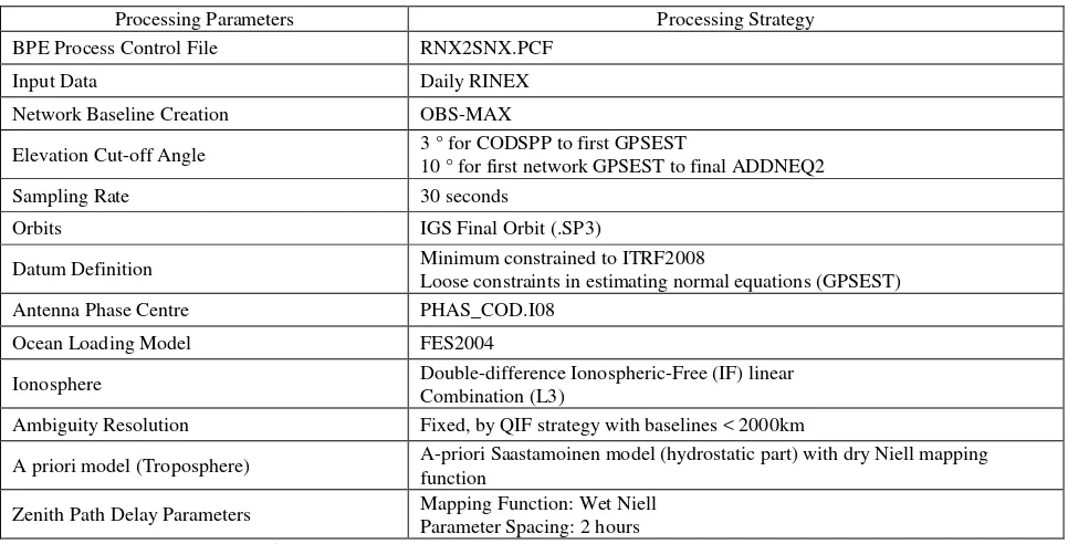
To estimate daily solutions of the MyRTKnet stations Bernese high-precision GNSS processing software version 5.0 was used by employing its double difference quasi-ionosphere free (QIF) strategy. 65 MyRTKnet stations and 24 IGS stations were
chosen with GNSS data spanning from December 2004 to December 2014. 15 out of the 24 IGS stations were selected (see figure 1) as fiducial stations for datum definition as they represented stable motions throughout the data time span. The processing strategy and parameters adopted are given in table
Figure 1. Fiducial and non-fiducial IGS stations selected for Bernese processing
Processing Parameters Processing Strategy
BPE Process Control File RNX2SNX.PCF
Input Data Daily RINEX
Network Baseline Creation OBS-MAX
Elevation Cut-off Angle 3 ° for CODSPP to first GPSEST
10 ° for first network GPSEST to final ADDNEQ2
Sampling Rate 30 seconds
Orbits IGS Final Orbit (.SP3)
Datum Definition Minimum constrained to ITRF2008
Loose constraints in estimating normal equations (GPSEST)
Antenna Phase Centre PHAS_COD.I08
Ocean Loading Model FES2004
Ionosphere Double-difference Ionospheric-Free (IF) linear
Combination (L3)
Ambiguity Resolution Fixed, by QIF strategy with baselines < 2000km
A priori model (Troposphere) A-priori Saastamoinen model (hydrostatic part) with dry Niell mapping function
Zenith Path Delay Parameters Mapping Function: Wet Niell Parameter Spacing: 2 hours
4.2 Time series analysis and velocity estimation for Malaysia from MyRTKnet
After the daily solutions were estimated, a time series of daily solutions for the selected MyRTKnet stations were plotted using GITSA, a software developed by [43] for time series analysis using MATLAB. With GITSA, daily SINEX solutions were converted to Cartesian coordinates and stored in GTS files for each station. The Cartesian coordinates were then converted to local (N, E, U) coordinates, replacing the Cartesian coordinates in the GTS files. Note that the Up component is the ellipsoidal height.
Once each station‟s time series was plotted, the outliers were removed as it may affect the linear regression line later for estimating the velocity vectors. This was executed automatically via GITSA through outlier detection and removal. All outliers were removed at 99% confidence level. The linear least squares regression analysis was executed within GITSA as well. The determination of velocity vectors from linear least squares regression must fulfil two criteria: (1) minimum of 4 years solution in order to reduce annual and semi-annual effects in geodetic time series, which will cause a bias to the estimated velocities (Blewitt and Lavallée, 2002) and (2) time series with large data gaps are not chosen to estimate the velocity vectors.
5. RESULTS AND DISCUSSION
As mentioned, there have been four major earthquakes that have affected Malaysia, with the most prominent being the 2004 Sumatra-Andaman earthquake which has caused a long-term post-seismic relaxation process (Paul et al., 2012). Coupled with the frequent earthquakes from the Sumatran subduction zone, Malaysia seems to undergo inter-seismic deformation, rather than post-seismic deformation. Inter-seismic deformation usually occurs after the post-seismic deformation has decayed. However, the authors decided to adopt the definition by Hetland and Hager (2006) who defined inter-seismic deformation as any deformation during the earthquake cycle that does not include the co-seismic deformation, which includes post-seismic deformation as well.
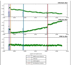
With reference to figure 2, the time series for UPMS station positions exhibits the four major earthquakes that affected Malaysia. UPMS is chosen as it located in the central region of Peninsular Malaysia, which is affected by all four earthquakes. The time series covers station positions from December 2004 to
December 2014. Beginning from 1st December 2004, the time series immediately depicts the co-seismic displacement due to the 2004 Sumatra-Andaman earthquake. Then, without clearly exhibiting a post-seismic motion, the 2005 Nias earthquake occurred early in the year causing further displacements. The effect from this shows a post-seismic motion in, especially, the east component: initially heading west, but in 2006 there is a slow change towards east direction and this continued on for the following years, with the Bengkulu earthquake not having much of an impact to the UPMS time series but has a small impact in South Peninsular Malaysia (see table 6). The 2012 Northern Sumatra earthquake, however, does show a change in direction and steepness of the time series, whereby the North component is less steep after the 2012 earthquake, while east component had a major post-seismic motion directly after the 2012 earthquake with a spike in the time series lasting a few months, i.e., from 11 April 2012 to 31 August 2012. The east component then levels back but the steepness and direction remains almost the same. However, as the north component slows down, this means there will be a major effect on the velocities before and after the 2012 earthquake. Therefore, to have a single period to represent the secular velocities of Malaysia would not be appropriate as even the underlying velocities seem to change after earthquakes.
From years 2008 to 2011 (4 years), UPMS did not experience any episodic deformation. This time-span would adequately represent the Malaysian secular inter-seismic deformation between the 2004 earthquake and the 2012 earthquake. Moreover, the velocities determined from this 4-year period would be significantly less influenced by annual and semi-annual effects. Note that, in terms of stable motion from years 2008 to 2011, the results are similar for all MyRTKnet station.
However, to determine the motion for the following years after the 2008-2011 inter-seismic period, new linear velocities have to be determined from the time series after the major post-seismic motion (spike) due to the 2012 earthquake, i.e., from 1 September 2012 to 31 December 2014. Since this new velocities will only cover a period of 2 years and 4 months, it would be affected by annual and semi-annual effects; thus, affecting the overall accuracy of the deformation model after the 2012 earthquake. Therefore, for this paper, only the 2008-2011 inter-seismic periods is discussed in detail. This will not cause any issues in achieving the objective of this paper, as this information will help facilitate the proposal for the implementation of a semi-dynamic datum for Malaysia. The International Archives of the Photogrammetry, Remote Sensing and Spatial Information Sciences, Volume XLII-4/W5, 2017
GGT 2017, 4 October 2017, Kuala Lumpur, Malaysia
This contribution has been peer-reviewed.
Figure 2. UPMS (University Putra Malaysia) MyRTKnet station time series depicting the 2008-2011 inter-seismic period and co-seismic effects due to earthquakes. UPMS was chosen as it is affected by all the aforementioned nearby earthquakes.
Region Average Velocity (cm/yr) (2008 – 2011)
VN VE
North-west Peninsular Malaysia – Perlis, Kedah, Perak, Kelantan border, and Perak-Selangor border
-1.09 ±0.02 1.17 ±0.02
North-east Peninsular Malaysia – Kelantan,
Terengganu, Pahang -0.77 ±0.01 1.79 ±0.02
Central Peninsular Malaysia – Selangor and
Negeri Sembilan -0.81 ±0.01 1.89 ±0.02
South Peninsular Malaysia – Melaka and Johor -0.85 ±0.01 2.18 ±0.02
Sarawak, Malaysia -1.00 ±0.01 2.56 ±0.02
Sabah, Malaysia -1.12 ±0.01 2.45 ±0.02
Table 5. Averaged velocities of Malaysia, categorized by area, from linear regression analysis of MyRTKnet station positions from 2008 to 2011. VN and VE represent the average north component and east component velocity, and their standard errors,
respectively
From table 5, between 2008 and 2011, Peninsular Malaysia moves south-east at an average velocity of -0.89 ±0.01 cm/yr for the north component, and 1.70 ±0.02 cm/yr for the east component, while East Malaysia (Sabah and Sarawak) moves south-east as well, at an average velocity of -1.06 ±0.01 cm/yr for the north component and 2.50 ±0.02 cm/yr for the east component. Both regions are moving at almost the same velocity, yet the east component of East Malaysia has a 7 mm/yr difference compared to Peninsular Malaysia. The Up component is better analysed with regard to a particular station or region; thus, only the North and East velocities are focused. Based on the findings, AMAN is the only station that exhibits a different direction with an exceptionally high velocity at 2.45 ±0.02 cm/yr north, 3.06 ±0.02 cm/yr east, and -3.35 ±0.03 cm/yr up. This is, without a doubt, due to land subsidence that occurs at the station; hence, it is removed from the average velocity results above as well as the secular deformation model.
There is no evident reason as to why East Malaysia moves at a faster rate compared to Peninsular Malaysia, even though East Malaysia is relatively stable and is not affected by major seismic events compared to Peninsular Malaysia (see figure 3). Further research in understanding earthquake mechanism is much needed, however that is beyond the scope of this paper. Nonetheless, from these results, it is evident that Peninsular and East Malaysia should be modelled separately as the rates are much dissimilar.
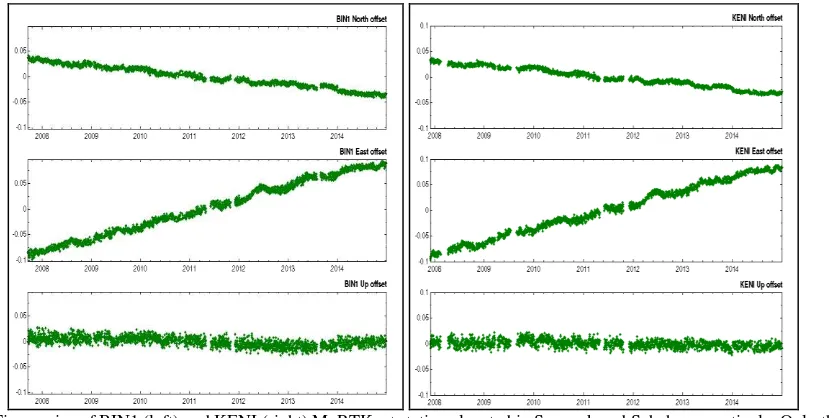
displacement for the four major earthquakes. East Malaysia exhibited nil or minor displacements (below 5 mm) for all four
earthquakes. The displacement values are determined via simple coordinate differentiation before and after an earthquake
Figure 3. Time series of BIN1 (left) and KENI (right) MyRTKnet stations located in Sarawak and Sabah, respectively. Only the 2012 earthquake has a slight effect (few mm) on the east component in East Malaysia which can be considered negligible. Many East
Malaysia MyRTKnet stations began operating towards the end of 2007, with mostly being established in April 2009
Earthquake Displacement of Peninsular Malaysia (cm)
North Region South Region
North East North East
min max min max min max min max
2004 Sumatra-Andaman 0.53 3.15 11.68 16.13 0.35 0.73 1.84 4.39
2005 Nias 0.98 3.73 1.27 4.17 0.04 1.98 0.30 4.72
2007 Bengkulu 0.10 1.35 0.01 1.14 1.33 2.19 0.43 1.56
2012 Northern Sumatra 0.12 2.27 1.21 4.49 0.03 1.06 0.78 2.69
Table 6. Maximum and minimum co-seismic displacements in Peninsular Malaysia due to the four major earthquakes
From table 6, the values derived are almost similar to the values by DSMM (2009). The co-seismic effect of the 2005 Nias, 2007 Bengkulu and 2012 Northern Sumatra earthquakes are less significant relative to the 2004 Sumatra-Andaman earthquake; hence, it would not have a considerable effect to the long-term tectonic motion of Malaysia. Nevertheless, it is noted that the 2005 Nias earthquake does have a considerable effect as observed in figure 2. The dislocation and the further post-seismic motion evidently show that it had a large impact on Peninsular Malaysia. This can also be observed with the 2012 Northern Sumatra earthquake, especially with their co-seismic displacements values that are almost similar. It should also be noted that the 2012 Northern Sumatra earthquake even has an effect on East Malaysia (see figure 3), though benign but it portrays a significant impact. Hence, the 2012 Northern Sumatra earthquake requires further study on its long-term effects on the tectonic motion of Malaysia, e.g., by additional GPS data from 2015 onwards.
Overall, from figure 2 and table 5, Malaysia undergoes inter-seismic motion from 2008 to 2011, which can serve as the secular deformation model of Malaysia for a period between 1 June 2005 (~2 months after the 2005 Nias earthquake when the post-seismic effect had reduced) and 1 April 2012 (before the 2012 Northern Sumatra earthquake) since there are no significant earthquakes that can alter the secular motion during
this period. A new secular deformation model will be needed for the motion after the 2012 Northern Sumatra earthquake. No velocities are shown after then 2012 Northern Sumatra earthquake due to its short time span of available data which may cause bias linear velocity estimations. Hence, it can be deduced here that Malaysia does undergo complex seismic activity as it requires at least 2 secular deformation models. Additionally, since dislocation in station position would most definitely produce poor secular velocity estimations, non-secular deformation must be treated separately, such that by a dislocation model (Denys et al., 2007; Stanaway et al., 2012). Thus, non-secular models, i.e., co-seismic displacements, will be added to the secular models for certain epochs that are affected by earthquakes. The information gathered here will be primarily used in the next part: to propose a semi-dynamic datum approach for Malaysia.
6. PROPOSED DESIGN FOR IMPLEMENTING A SEMI-DYNAMIC DATUM FOR MALAYSIA
The basic realization of a semi-dynamic datum is based on two main elements which are the deformation model and a defined reference epoch. In this paper, an optimal design for developing and implementing a semi-dynamic datum for Malaysia is proposed. The first step is updating the existing geocentric The International Archives of the Photogrammetry, Remote Sensing and Spatial Information Sciences, Volume XLII-4/W5, 2017
GGT 2017, 4 October 2017, Kuala Lumpur, Malaysia
This contribution has been peer-reviewed.
datum, i.e., GDM2000, to a more recent reference epoch to be in line with current ITRF2008 reference frame. The reference epoch 22nd April 2009 is chosen as it during the stable
inter-seismic period and due to the fact that all 78 MyRTKnet stations were established and readily utilised towards the mid of April 2009. Consequently, the published GDM2000 (2000.00) coordinates at epoch 1st January 2000 is transformed to the updated GDM2000 (2009.3055) at epoch 2009.3055 or 22nd April 2009 using the Geographic Offset transformation. Geographic Offset transformation relates both datum systems with only two parameters: the difference in the geographic latitude and the difference in the geographic longitude. This transformation method employed due to the complex deformation of Peninsular Malaysia, whereby North-west Peninsular Malaysia has a large velocity difference compared with North-east and Central regions, with a similar situation for South Peninsular Malaysia. Henceforth, this updated GDM2000 will be called GDM2000 (2009) at epoch 22nd April 2009 which will serve as the reference epoch for the semi-dynamic datum and as a new geodetic datum for users who wish to use this set of coordinates.
Next, a deformation model that consists of secular velocities, i.e., secular deformation model, and non-secular displacements, i.e., non-secular deformation model, will be generated based on the same reference frame and epoch of GDM2000 (2009.3055). Both models are employed for Malaysia as the deformation of Malaysia comprises both secular and non-secular seismic activity. The secular and non-secular deformation model to comply with Malaysia will be discussed in detail in the later sub-sections.
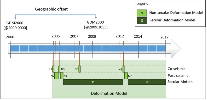
Additionally, for the secular deformation model, it will be used to predict the coordinates of the foreseeable future. As mentioned, maintaining the accuracy around 5 cm for 10 years (Blick and Grant, 2010) does seem implausible with frequent major earthquakes affecting Malaysia. Therefore, further studies are required to test the extent of which the secular deformation model is able to provide accurate coordinates. Figure 4 illustrates a timeline from year 2000 to 2017 (arbitrary future) that involves the Geographic Offset transformation and deformation model, whereby these two approaches will be applied to transform and propagate coordinates, respectively.
Figure 4. Timeline Proposal (2000 – 2017) for implementing a semi-dynamic datum for Malaysia. There will be 2 secular models representing the stable periods for Malaysia, which are S1 and S2. There are also 7 non-secular models each representing a
co-seismic and post-co-seismic displacement from particular earthquakes. The N1, N3, N5 and N6 model represents the non-secular displacements due to the 2004 Sumatra-Andaman, 2005 Nias, 2007 Bengkulu and 2012 Northern Sumatra earthquakes, respectively.
While the N2, N4 and N7 model represents the major post-seismic spike that occurs after the Sumatra-Andaman, Nias and Northern Sumatra earthquake, respectively. Both models will be used depending on the chosen target epoch, as well as the Geographic Offset
transformation model. All models will be mapped with a 6‟ grid size, or ~11km, in order to reduce the chances of mismatch interpolation such as between the North-west and North-east region if the user‟s position is almost in between the two regions
From figure 4, the idea is to use both secular and non-secular models to propagate positions to a desired epoch. The position and the propagation value are related by a bilinear interpolation approach with 6‟ grid. Therefore, two information are needed: the spatial and temporal information. The temporal information (day-of-year) is required to determine which model(s) to be used, i.e., secular or/and non-secular deformation models, e.g., S1 + N5 +S1 models to obtain coordinates in epoch January 2007 from the reference epoch 2009.3055. While the spatial information (coordinates) is to determine the displacement, or propagation, value based on interpolation of MyRTKnet stations nearby, since each MyRTKnet station has secular and non-secular values. This is illustrated clearly in the next sections.
6.1 Deformation Model for Malaysia
The results in section 5 are used to determine the secular velocities and non-secular displacements. The methodology for developing the deformation model for Malaysia is divided into two modules: (1) secular deformation modelling, (2) non-secular deformation modelling.
6.1.1 Secular Deformation Modeling
results from the GPS are discrete; hence, it is essential to define the velocities at a higher density and through a spatial function model such as mentioned in table 2.
For the secular deformation model of Malaysia, it is proposed to use bilinear interpolation to estimate velocities at other points, such as that used by New Zealand. The MyRTKnet stations are sufficiently dense; hence, allowing the utilization of bilinear
interpolation which should provide satisfactory accuracy over Malaysia. Furthermore, from table 5, there are no very large discrepancies between each region, in terms of direction and rate; thus, it would not cause any incorrect interpolations of velocity estimation. Besides, at present, there are no concrete findings on the Euler pole of the Sundaland block.
Peninsular Malaysia: North component Peninsular Malaysia: East component
East Malaysia: North component East Malaysia: East component
Figure 5. Malaysian 2008-2011 secular deformation model of north and east velocities using bilinear interpolation
As mentioned, the 2008-2011 period will be used to realize the secular deformation model which can be used for a period between 1 June 2005 (~2 months after the 2005 Nias earthquake when the post-seismic effect had reduced) and 1 April 2012 (before the 2012 Northern Sumatra earthquake). While the second secular deformation (2012 onwards) needs further data of subsequent years in order to have better model.
In addition, based on the results from section 5, since Peninsular Malaysia undergoes a more complex seismic activity than East Malaysia, it is proposed that the Peninsular and East Malaysia be separately modelled as depicted in figure 5. The north and east components are modelled separately in order to ease the propagation computation. Basically, 2D translation propagation is applied to the coordinates.
6.1.2 Non-secular deformation modelling
Non-secular deformation models are usually based on the dislocation models or methods as stated in table 2. In the case of Malaysia, the authors propose a rudimentary approach, such as the Kriging interpolation method employed in Japan and Australia, which is the bilinear interpolation method for
modelling the non-secular displacements – the same method used for interpolating the secular velocities. For the post-seismic effect after the 2012 Northern Sumatra earthquake, a 2nd degree polynomial function is employed to determine the coordinates during this period; only then the bilinear interpolation method is used per usual.
Even though dislocation models such as the Okada model (Okada, 1985) is more suitable, since it takes into account the decay period after the earthquake, bilinear interpolation method is chosen for the present proposal due its simplicity in adoption and availability of a fairly dense geodetic network. Studies regarding seismic activity are still considerably new in Malaysia, however, in future; the authors would like to improve the current proposed non-secular deformation model to adopt the Okada model such as used in the paper by Vigny et al. (2005).
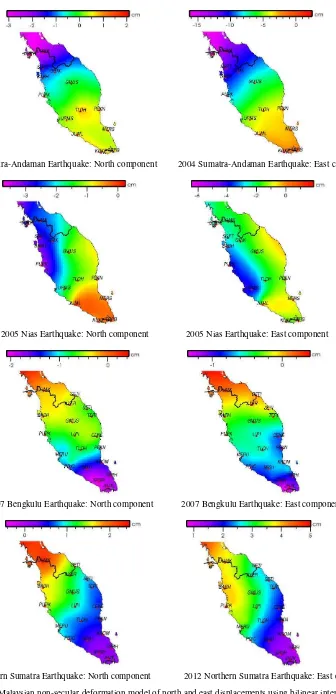
Figure 6 below shows the non-secular deformation models which will be employed in the semi-dynamic datum of Malaysia. East Malaysia is not modelled for non-secular deformations as the earthquakes have nil to almost negligible (< 5mm) co-seismic effects.
The International Archives of the Photogrammetry, Remote Sensing and Spatial Information Sciences, Volume XLII-4/W5, 2017 GGT 2017, 4 October 2017, Kuala Lumpur, Malaysia
This contribution has been peer-reviewed.
2004 Sumatra-Andaman Earthquake: North component 2004 Sumatra-Andaman Earthquake: East component
2005 Nias Earthquake: North component 2005 Nias Earthquake: East component
2007 Bengkulu Earthquake: North component 2007 Bengkulu Earthquake: East component
2012 Northern Sumatra Earthquake: North component 2012 Northern Sumatra Earthquake: East component
6.2 Managing coordinate propagation within the semi-dynamic datum for Malaysia
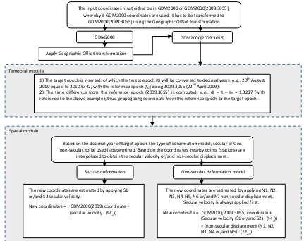
The management of coordinate propagation requires a database management system (DBMS) that basically manages coordinate propagation by selecting and applying the deformation models. In this paper, the authors propose a process framework within the DBMS of the semi-dynamic datum of Malaysia. Figure 7 illustrates and explains the step-by-step process framework of the DBMS.
The DBMS consists of: (1) a datum transformation model, i.e., Geographic Offset transformation, (2) a temporal module which propagates coordinates to a target epoch, (3) a spatial module that determines the deformation model required (based on the temporal module and location of the coordinates) and then estimates the secular velocity or/and the non-secular displacement, by applying the secular or/and non-secular deformation models, respectively, via the bilinear interpolation method. The secular and non-secular deformation models support forward (after reference epoch 2009) and backward (before reference epoch 2009) propagations.
The proposed DBMS will be using MATLAB programming language, and is currently in progress. The program will have a user-friendly graphical user interface (GUI) using GUIDE.
6.3 Implications and limitations of adopting a semi-dynamic datum for Malaysia
Adopting a semi-dynamic datum for Malaysia will have its challenges, especially concerning the cadastral database. Some limitations have been pointed out in table 3; though it is mainly based on literature from the New Zealand‟s semi-dynamic datum, it is applicable to Malaysia as well. Table 7 highlights the major implications in terms of pros and cons (limitations) for adopting a semi-dynamic datum for Malaysia.
These limitations have to be addressed before practical implementation of a semi-dynamic datum for Malaysia. Therefore, many discussions are needed among the authorities, especially the agencies that deal with survey and mapping, for a unified and coordinated geospatial database. There is also the issue of East Malaysia still adopting a conventional geodetic datum.
Figure 7. The proposed process framework for the DBMS of the semi-dynamic datum for Malaysia The input coordinates must either be in GDM2000 or GDM2000[2009.3055],
whereby if GDM2000 coordinates are used, it has to be transformed to GDM2000[2009.3055] using the Geographic Offset transformation
GDM2000[2009.3055] GDM2000
Apply Geographic Offset transformation
1) The target epoch is inserted, of which the target epoch (t) will be converted to decimal years, e.g., 20th August 2010 equals to 2010.6342, with the reference epoch (t0) being 2009.3055 (22
nd
April 2009).
2) The time difference from the reference epoch (2009.3055) is computed, e.g., dt = t – t0 = 1.3287 (with
reference to the above example); thus, propagating coordinate from the reference epoch to the target epoch.
Based on the decimal year of target epoch, the type of deformation model, secular or/and non-secular, to be used is determined. Based on the coordinates, nearby points (stations) are
interpolated to obtain the secular velocity or/and non-secular displacement.
The new coordinates are estimated by applying S1 or/and S2 secular velocity.
New coordinates = GDM2000(2009) coordinate + (secular velocity · (t-t
o))
Secular deformation model
Non-secular deformation model
The new coordinates are estimated by applying N1, N2, N3, N4, N5, N6 or/and N7 non-secular displacement.
Secular velocity is always applied first.
New coordinate = GDM2000[2009.3055] coordinate + (Secular velocity (S1 or/and S2) · (t-t
o))
+ (non-secular displacement (N1, N2, N3, N4 or/and N5) · (t-t
o))
Temporal module
Spatial module
The International Archives of the Photogrammetry, Remote Sensing and Spatial Information Sciences, Volume XLII-4/W5, 2017 GGT 2017, 4 October 2017, Kuala Lumpur, Malaysia
This contribution has been peer-reviewed.
Implications Pros
• The semi-dynamic datum would provide accurate coordinates over time by taking into account secular and non-secular deformations of Malaysia. Thus, allowing for more reliable apriori coordinates, especially required for the latest positioning techniques such as Precise Point Positioning (PPP).
• Does not require a costly and time-consuming geodetic datum update whenever an earthquake occurs, resulting in many versions of a national geodetic datum which may cause confusion at the user level.
Cons (Limitations)
• The users have to be highly knowledgeable in order to understand reference epochs and the deformation model structure, especially in terms of the forward and backward propagations. This may cause annoyance to some who wish to transform or propagate coordinates easily without the hassle of selecting a target epoch.
• With the occurrence of mega-earthquakes, e.g., 2004 Aceh-Andaman earthquake, the post-seismic motion may take years to decay. According to Paul et al. (2012), the post-seismic relaxation processes continue in Andaman. Therefore, for countries that experience inter-seismic deformation, or long-term post-seismic motion, the deformation model may require updates for the secular velocities; whereby, determining secular velocities requires a long period of stable motion. This is the present issue with the secular deformation model after the 2012 Northern Sumatra earthquake.
• Ideally, the adoption of a semi-dynamic datum requires the cadastral database to be updated as well. However, in a practical sense, this is difficult to implement in Malaysia, as the NDCDB has internal issues at present. This would be the primary hurdle in implementing a semi-dynamic datum for Malaysia.
Table 7. Implications and limitations for adopting a semi-dynamic datum for Malaysia
7.0 SUMMARY AND CONCLUDING REMARKS
The objective of this paper has been achieved, whereby the proposed design for implementing a semi-dynamic datum for Malaysia has been thoroughly described and illustrated. The seismic activity of Malaysia was investigated as well, of which is vital for the aforementioned proposed design. The implications of implementing a semi-dynamic datum for Malaysia have also been outlined.
The results from the investigation of the seismic activity indicated that Malaysia is indeed affected by a complex deformation. For the secular deformation, region-averaged velocities are tabulated in table 5. Between 2008 and 2011, Malaysia underwent a steady inter-seismic motion which serves as the secular deformation model, i.e., S1, from 1 June 2005 (~2 months after the 2005 Nias earthquake when the post-seismic effect had reduced) to 1 April 2012 (before the 2012 Northern Sumatra earthquake), since there are no significant earthquakes that can alter the secular motion during this period. Within this inter-seismic period, Peninsular Malaysia moves south-east at an average velocity of -0.89 ±0.01 cm/yr for the north component, and 1.70 ±0.02 cm/yr for the east component, while East Malaysia (Sabah and Sarawak) moves south-east as well, at an average velocity of -1.06 ±0.01 cm/yr for the north component and 2.50 ±0.02 cm/yr for the east component. From these results, it is clear that Peninsular and East Malaysia are not coherent; hence, are modelled separately. As for the non-secular deformation, the co-seismic displacements are tabulated in table 6. The co-seismic displacement of the 2005 Nias, 2007 Bengkulu and 2012 Northern Sumatra earthquakes are less significant relative to the 2004 Sumatra-Andaman earthquake; however, the 2012 Northern Sumatra earthquake had a significant impact on Malaysia. Due to the 2012 Northern Sumatra earthquake, the north component seems to be decelerating which in turn would have a substantial effect on the velocity. As a result, the motion after this earthquake has to be modelled exclusively; thereby a second secular deformation model is proposed, i.e., S2. However, further data is needed to
completely ascertain this theory, i.e., rates deceleration, and to determine the velocity, since 4 years of stable motion is required in order produce unbiased velocities.
From the above results, the design of the semi-dynamic datum for Malaysia is proposed. The design consists of a datum transformation model, i.e., Geographic Offset transformation, a temporal module which propagates coordinates to a target epoch, and a spatial module that determines the deformation model required, which then estimates the secular velocity or/and the non-secular displacement, by applying the secular or/and non-secular deformation models, respectively, via a bilinear interpolation method. This is described in detail in figure 7, i.e., the process framework of the semi-dynamic datum for Malaysia. The next steps for this research include validation of the semi-dynamic datum for Malaysia by carrying out accuracy tests at various locations and epochs, and addressing the aforementioned limitations. If this proposed design proves successful, future research into dislocations models such as the Okada model (Okada, 1985) for enhancing the non-secular deformation models, and rheological models such as Burgers model for modelling the secular inter-seismic deformation of Malaysia can be studied. The Burgers rheological model is suitable for modelling steady-state post-seismic motion of GPS time-series several hundred kilometers away from earthquake rupture (Pollitz et. al., 2006; Pollitz et. al. 2008; Höchner and Soboley, 2010). Overall, this study has demonstrated that implementing a semi-dynamic datum for Malaysia is feasible with respect to the proposed design.
ACKNOWLEDGEMENTS
Authors would like to acknowledge the Department of Surveying and Mapping, Malaysia for providing the data and Ministry of Higher Education and Universiti Teknologi Malaysia for financial support through GUP grant (Vote: 11H74).
REFERENCES
Altamimi, Z., Rebischung, P., Metivier, L., Collilieux, X., 2016. ITRF2008: A New Release of the International Terrestrial Reference Frame Modelling Nonlinear Station Motion. Journal of Geophysical Research Solid Earth, 121(8), pp. 6109-6131.
Beavan, J., 2008. GNS Science Consultancy Report 2008/136: 79 “Consultancy services for PositioNZonLine, Phase 2 (PONL-02)”, GNS Science, Lower Hutt, New Zealand.
Beavan, J. and Blick, G., 2005. Limitations in the NZGD2000 deformation model. Dynamic Planet 2005 - International Association of Geodesy Conference, Cairns, Australia.
Blewitt, G. and Lavallée, D., 2002. Effect of annual signals on geodetic velocity. Journal of Geophysical Research: Solid Earth. 107(B7).
Blick, G., and Grant, D., 1998. Possibility of a dynamic cadastre for a dynamic nation. In Advances in Positioning and Reference Frames, Springer Berlin Heidelberg. Pp. 107-113.
Blick, G., and Grant, D., 2010. The Implementation of a Semi-dynamic Datum in New Zealand – Ten Years On. Proceedings of FIG Congress 2010, Sydney, Australia, April 11-16.
Blick, G., Crook, C., Grant, D., and Beavan, J., 2005. Implementation of a semi-dynamic datum for New Zealand. In A Window on the Future of Geodesy. Sapporo, Japan: Springer Berlin Heidelberg. 128, pp. 38-43.
Blick, G., Donnelly, N., and Jordan, A., 2009. The practical implications and limitations of the introduction of a semi-dynamic datum–a New Zealand case study. In Geodetic Reference Frames. Springer Berlin Heidelberg, pp. 115-120.
Dach, R., Hugentobler, U., Fridez, P. and Meindl, M., 2007. Bernese GPS Software Version 5.0. Astronomical Institute, University of Bern, Switzerland.
Denys, P., Winefield, R., and Jordan, A., 2007. Incorporating localised deformation events in dynamic datums. Proceedings of FIG General Assembly and Working Week 2007, Hong Kong, May 13-17.
Drewes, H., 2009. Reference Systems, Reference Frames, and the Geodetic Datum – Basic Considerations. In Observing our Changing Earth. 133, pp. 3-9. Springer Berlin Heidelberg.
Drewes, H., and Heidbach, O., 2005. Deformation of the South American crust estimated from finite element and collocation methods. In A Window on the Future of Geodesy. Sapporo, Japan: Springer Berlin Heidelberg. 128, pp. 544-549.
DSMM, 2009. Technical Guide to the Coordinate Reference Systems “PKPUP1-2009 Circular”. Department Survey and Mapping Malaysia, Kuala Lumpur.
Even-Tzur, G., 2011. Updating the Semi-Dynamic Datum of Israel. Surveying and Land Information Science, 71(2), pp. 41-47.
Ferland, R. and Piraszewski, M., 2009. The IGS-combined station coordinates, earth rotation parameters and apparent geocenter. Journal of Geodesy. 83(3-4) pp. 385-392.
Fortes, L. P., Lauria, E., Brunini, C., Amaya, W., Sanchez, L., Drewes, H., and Seemüller, W., 2006. Current status and future developments of the SIRGAS Project. Wissenschaftliche Arbeiten der Fachrichtung Geodäsie und Geoinformatik der Universität Hannover. 258, pp. 59-70. Assembly, Colorado, USA. July 2-14.
Grant, D., and Crook, C., 2012. Spatial maintenance of the New Zealand cadastre in response to earthquakes. Proceedings of FIG Working Week 2012, Rome, Italy, May 6-10.
Grant, D.B. and Blick G.H., 1998. A new geocentric datum for New Zealand (NZGD2000). New Zealand Surveyor. 288, pp. 40–42.
Haasdyk, J., Donnelly, N., Harrison, C., Rizos, C., Roberts, C., and Stanaway, R., 2014. Options for Modernising the Geocentric Datum of Australia. Research@Locate'14 Conference, Canberra, Australia, 07-09 April.
Hetland, E. A., and Hager, B. H., 2006. Interseismic strain accumulation: Spin‐up, cycle invariance, and irregular rupture sequences. Geochemistry, Geophysics, Geosystems. 7(5).
Hiyama Y., Yamagiwa, A., Kawahara, T., Iwata, M., Fukuzaki, Y., Shouji, Y., Sato, Y., Yutsudo, T., Sasaki, T., Shigematsu, H., Yamao, H., Inukai, T., Ohtaki, M., Kokado, K., Kurihara, S., Kimura, I., Tsutsumi, T., Yahagi, T., Furuya, Y., Kageyama, T., Kawamoto, S., Yamaguchi, K., Tsuji, H., and Matsumura, S., 2011. Revision of Survey Results of Control Points after the 2011 off the Pacific Coast of Tohoku Earthquake, Bulletin of the GSI, Vol. 59.
Höchner, A. and Sobolev, S. V., 2010: Constraining rheology of the asthenosphere based on postseismic GPS and geoid observations. Proceedings of International Geological Modelling Conference - GeoMod 2010, Lisbon, Portugal. September 27-29.
Jekeli, C., 2012. Geometric Reference Systems in Geodesy (2012 edition). Ohio.
Jordan, A., Denys, P., and Blick, G., 2007. Implementing Localised Deformation Models into a Semi-Dynamic Datum. In Dynamic Planet: Monitoring and Understanding a Dynamic Planet with Geodetic and Oceanographic Tools. Cairns, Australia: Springer Berlin Heidelberg. 130, pp. 631-637.
Kelly, K. M., 2012. Towards implementing dynamic datum data management in GIS. FIG Working Week Conference. Rome, Italy, 6-10 May.
Mccaffrey, R., 2002. Crustal Block Rotations and Plate Coupling, In Plate Boundary Zones. Washington, D. C.: American Geophysical Union, pp.101-122.
The International Archives of the Photogrammetry, Remote Sensing and Spatial Information Sciences, Volume XLII-4/W5, 2017 GGT 2017, 4 October 2017, Kuala Lumpur, Malaysia
This contribution has been peer-reviewed.
Okada, Y., 1985. Surface deformation due to shear and tensile faults in a half-space, Bulletin Seism. Soc. Am. 75: 1135–1154.
Paul, J., Rajendran, C. P., Lowry, A. R., Andrade, V., and Rajendran, K., 2012, Andaman postseismic deformation observations: Still slipping after all these years? Bulletin of the Seismological Society of America. 102(1), pp. 343–351.
Pearson, C., and Snay, R., 2013. Introducing HTDP 3.1 to transform coordinates across time and spatial reference frames. GPS Solutions. 17(1), pp. 1-15.
Pearson, C., McCaffrey, R., Elliott J. L., and Snay, R., 2010. HTDP 3.0: software for coping with coordinate changes associated with crustal motion. J Surv Eng.136, pp. 80–90.
Pollitz, F., Banerjee, P., Grijalva, K., Nagarajan, B., and Bürgmann, R., 2008. Effect of 3-D viscoelastic structure on post-seismic relaxation from the 2004 M=9.2 Sumatra earthquake: Geophysical Journal International. 173(1), pp. 189-204.
Pollitz, F.F., Bürgmann, R. and Banerjee, P., 2006. Post-seismic relaxation following the great 2004 Sumatra-Andaman earthquake on a compressible self-gravitating Earth: Geophysical Journal International. 167(1), pp. 397-420.
Rebischung, P., Griffiths, J., Ray, J., Schmid, R., Collilieux, X., and Garayt, B., 2012. IGS08: the IGS realization of ITRF2008. GPS solutions. 16(4), pp. 483-494.
Sánchez, L., 2011. IGS Technical Report “IGS Regional Network Associate Analysis center for SIRGAS (IGS RNAAC SIR)”, pp. 107-115.
Shariff, N. S. M., Musa, T. A., Omar, K., and Othman, R. 2014. The Geocentric Datum of Malaysia: Preliminary Assessment and Implications. In Geoinformation for Informed Decisions, pp. 71-83. Springer International Publishing.
Simons, M., Minson, S. E., Sladen, A., Ortega, F., Jiang, J., Owen, S. E., Meng, L., Ampuero,J., Wei, S., Chu, R., Helmberger, D. V., Kanamori, H., Hetland, E., Moore, A. W., and Webb, F. H. 2011. The 2011 magnitude 9.0 Tohoku-Oki earthquake: Mosaicking the megathrust from seconds to centuries. Science. 332(6036), pp. 1421-1425.
Simons, W. J. F., Socquet, A., Vigny, C., Ambrosius, B. A. C., Haji Abu, S., Promthong, Subarya, C., Sarsito, D. A., Matheussen, S., Morgan, P., and Spakman, W., 2007. A decade of GPS in Southeast Asia: Resolving Sundaland motion and boundaries. Journal of Geophysical Research: Solid Earth. 112(B6).
Stanaway, R., Roberts, C., and Blick, G., 2014. Realisation of a Geodetic Datum Using a Gridded Absolute Deformation Model (ADM). In Earth on the Edge: Science for a Sustainable Planet. Melbourne, Australia: Springer Berlin Heidelberg. 139, pp. 259-265.
Stanaway, R., Roberts, C., Blick, G., & Crook, C., 2012. Four Dimensional Deformation Modelling, the link between International, Regional and Local Reference Frames. Proceedings of FIG working Week 2012, Rome, Italy, May 6-10.
Steinberg, G., and Even-Tzur, G. 2005. Establishment of National Grid Based on Permanent GPS Stations in Israel. Surveying and Land Information Science. 65(1), pp. 47-52. Tanaka, Y., Saita, H., Sugawara, J., Iwata, K., Toyoda, T., Hirai, H., Kawaguchi, T., Matsuzaka, S., Hatanaka, Y., Tobita, M., Kuroishi, Y., and Imakiire, T., 2007. Efficient maintenance of the Japanese Geodetic Datum 2000 using crustal deformation models-PatchJGD & Semi-Dynamic Datum. Buletin Geog Surv Inst. 54.
Torge, W., 1980. Geodesy (1st ed.). New York: De Gruyter.
Tregoning, P., and Jackson, R., 1999. The need for dynamic datums. Geomatics Research Australasia, pp. 87-102.
USGS, 2014. Significant Earthquakes Archive. Retrieved
November 26, 2014, from
http://earthquake.usgs.gov/earthquakes/eqinthenews/
Vigny, C., Simons, W. J., Abu, S., Bamphenyu, R., Satirapod, C., Choosakul, N., Subarya, C., Socquet, A., Omar, K., Abidin, H. Z., and Ambrosius, B. A. C., 2005. Insight into the 2004 Sumatra–Andaman earthquake from GPS measurements in Southeast Asia. Nature. 436(7048), pp. 201-206.
Wessel, P. and Smith, W. H. F., 1998. New version of the generic mapping tools released, Eos Trans. AGU. 79(47), pp. 579.