ECCENTRICITY IN IMAGES OF CIRCULAR AND SPHERICAL TARGETS AND ITS
IMPACT TO 3D OBJECT RECONSTRUCTION
Thomas Luhmann
Jade University of Applied Sciences, Institute for Applied Photogrammetry and Geoinformatics, Oldenburg, Germany
Commission V, WG V/1
KEY WORDS: spherical target, circular target, sphere, eccentricity, spatial intersection, simulation
ABSTRACT:
This paper discusses a feature of projective geometry which causes eccentricity in the image measurement of circular and spherical targets. While it is commonly known that flat circular targets can have a significant displacement of the elliptical image centre with respect to the true imaged circle centre, it can also be shown that the a similar effect exists for spherical targets. Both types of targets are imaged with an elliptical contour. As a result, if measurement methods based on ellipses are used to detect the target (e.g. best-fit ellipses), the calculated ellipse centre does not correspond to the desired target centre in 3D space. This paper firstly discusses the use and measurement of circular and spherical targets. It then describes the geometrical projection model in order to demonstrate the eccentricity in image space. Based on numerical simulations, the eccentricity in the image is further quantified and investigated. Finally, the resulting effect in 3D space is estimated for stereo and multi-image intersections. It can be stated that the eccentricity is larger than usually assumed, and must be compensated for high-accuracy applications. Spherical targets do not show better results than circular targets. The paper is an updated version of Luhmann (2014) new experimental investigations on the effect of length measurement errors.
1. INTRODUCTION
1.1 Circular targets in practice
The use of circular targets is a standard procedure in close-range photogrammetry for measuring tasks of the highest accuracy. In contrast to other targets, e.g. chessboard-type patterns, circular targets offer a number of practical advantages:
Minimum size
Symmetric pattern with unique definition of the centre
Highly invariant with regard to rotation and scale
High image contrast achievable with small target area
Continuity of the feature contour
High-accuracy image measurement (< 1/20 pixel) via different algorithms, e.g. centroid or contour-based methods
Easy to manufacture, low cost
Active and passive targeting techniques (e.g. LEDs, fluorescent, retro-reflective, diffuse reflective)
Easily incorporated into target adapters for identifying well defined object features such as edges and drill holes
High degree of automation in the detection, measurement and identification of points (e.g. using coded targets)
However, some drawbacks can be identified for circular targets:
Eccentricity between ellipse centre and imaged circle centre if ellipse-based measurement algorithms are applied
Restricted visibility (typical: ±45°) depending on light sources and reflective properties
The target cannot be mechanically probed for comparative measurement, e.g. with a CMM
Risk of mistaken identity with other bright blob-shaped features
The benefits of high image contrast, minimal size and high precision in image measurement are of major importance, which explains the fact that circular targets are used in almost all high-accuracy photogrammetric applications (Clarke 1994, Robson and Shortis 2007, Luhmann 2010).
Retro-reflective spherical targets are often used as markers to provide all-around visibility and independence from the relative orientation between object (e.g. probe) and cameras. They are widely used in medical or motion-tracking applications (Figure 1) where different designs of spherical targets can be found (see Figure 2).
Figure 1: Example applications with spherical targets left: medical probing (Brainlab); right: motion tracking (IAPG)
Figure 2: Examples of spherical retro-targets (from left to right: IZI, Atesos, NDI, GMS)
Also, in industrial and other technical applications spheres are used in order to maximize visibility and enable tactile probing by other systems, e.g. coordinate measurement machines. In comparison to flat circular targets, the advantages of spheres can be listed as follows:
Large field of visibility
Can be mechanically probed for comparison purposes
However, a number of disadvantages can be identified:
Continuity of the image contour is broken where the sphere is attached to an object or mounting, or where images are taken from lower observation angles (>45-60°)
Blurred image edges resulting from the curvature of the sphere, which leads to some reduction in accuracy of image measurement
More difficult to manufacture, medium to high costs
Usually passive targeting techniques (mostly retro-reflective)
However, a target sphere still generates an elliptical image. Although the semi-axes are of more similar length, measurement eccentricity still exists. The effect is briefly mentioned in Luhmann et al. (2013), but not evaluated in detail. Figure 3 shows an example of a globe that appears as an ellipse if imaged off the optical axis.
Figure 3: Images of a globe in two different image positions
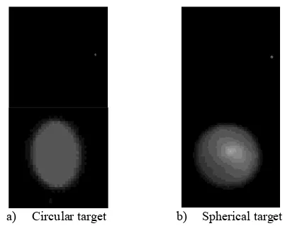
a) Circular target b) Spherical target Figure 4: Images of circular and spherical targets at similar image positions (top: original image; bottom: enlarged detail)
Figure 4 shows the images of a circular and a spherical target both with identical diameters and similar spatial position. The flat target is tilted by about 35 degrees with respect to the image plane. It can be seen that the circular target is imaged as an elongated ellipse, as expected. The image of the spherical target is elliptical as well while the semi-axes do not differ much. Note that the longer semi-axis appears in x-direction of the image.
1.2 Image operators for circular targets
The measurement of circular targets is usually performed by one of the following image methods:
Centroid operators: The centroid of the grey values or gradients of the target image pattern is calculated within a particular window. A threshold function can be introduced in order to include only those grey values which exceed the intensity threshold. Centroid operators are easy to
implement and have very fast computation times. They are suited to real-time applications and yield sub-pixel precision even for very small targets below 5 pixels in diameter. As a drawback, the centroid is very sensitive to pattern artefacts (e.g. occlusions or dirt) and image noise. In theory, the centre of gravity of the intensities corresponds to the imaged centre of the circle/sphere, hence the eccentricity in projection does not affect the result (Mahajan 1998) if diffuse target reflection without signal saturation can be assumed.
Template matching: Based on least-squares matching, a (synthetic) pattern is transformed onto the image, taking account of geometric and radiometric transformation parameters (Gruen 1985). The default affine transformation can be extended by projective or polynomial functions (Bethmann and Luhmann 2010). The adjusted shift parameters a0 and b0 are interpreted as the target centre. Partial derivatives for adjustment are derived from image gradients, hence the elliptical contour has maximum impact on the adjustment result. However, disturbances of the
target’s shape in the image can affect the centre positions.
Ellipse-based contour methods: Contour edge points are detected in grey-value profiles arranged in star patterns or parallel lines. A best-fit ellipse based on a general conic section is calculated for all contour points, yielding the centre coordinates of the ellipse. Disturbances along the edge of the ellipse can be eliminated by robust error detection.
Feature detectors: Based on the idea of Förstner's interest operator (Förstner & Gülch 1987) Ouellet & Hébert (2009) has developed a feature detector that considers the elliptical contour of a circular target. The result of the operator is, in theory, free of eccentricity.
1.3 Objectives and research topics
As further discussed in the next section, the centre of the elliptical image of a circular target is displaced with respect to the actual target centre due to the properties of projective geometry. From investigations such as Ahn (1997) and Dold (1997) and the long-term experience of system suppliers, users and developers, this eccentricity can be neglected in practice if the diameter of imaged targets is small enough, e.g. less than 10 pixels. However, since a) modern CCD and CMOS image sensors consist of much smaller physical detector elements (down to 1µm), b) image measuring accuracies in the order of 1/50 – 1/100 pixel can be achieved and c) accuracy requirements can be increased in practice, the impact of eccentricity in projection of circular targets must be revised.
On the basis of the above knowledge and experience, this paper addresses the following questions with respect to current systems and specifications:
What is the metric effect of eccentricity in projection for typical imaging scenarios?
How does this eccentricity affect the resulting 3D coordinates in simple stereo configurations or in complex multi-image scenes?
Is it possible to correct for eccentricity a priori using image measurements only?
Is there a significant difference in using flat circular targets or spherical targets?
These questions are of both theoretical interest and practical relevance. As one example, off-the-shelf systems use hand-held probes with calibrated circular or spherical targets. The probe can be positioned in almost any combination of distance and orientation within a large measuring volume, so that images of target points range from very small to very large. These online systems can be found in numerous applications (e.g. medical navigation, robot control, alignment of workpieces etc.). In contrast to multi-image configurations they provide only limited possibilities for the statistical control of measurements. Thus, systematic image measuring errors will have a significantly higher impact on 3D measurements from online systems in contrast to multi-image offline systems where 3D coordinates are calculated by robust bundle adjustment.
2. ECCENTRICITY IN PROJECTION
2.1 3D circle
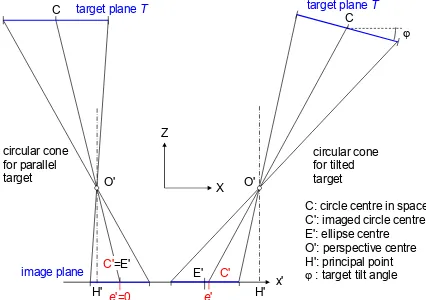
The projective imaging of a flat circular target can be described by a general conic intersection. Firstly, the 3D circle of the target creates, in general, an oblique circular cone of rays whose apex is given by the perspective centre of the image (Figure 5 right). The resulting image is then given by the intersection of the image plane with this cone. This intersection is a general ellipse with five independent parameters (2 translations, 2 semi-axes, 1 rotation angle). A comprehensive description of the ellipse geometry and the estimation of ellipse parameters from contour points is given in Luhmann et al. (2013).
e'
Figure 5: Eccentricity in projection of a circular target left: parallel planes; right: tilted planes
The centre of the image ellipse is identical to the imaged circle centre only in the case where circle plane and image plane are parallel to each other (Figure 5 left). The effect is well known and was investigated by Ahn (1997), and by Dold (1997) for high-accuracy photogrammetry systems. Dold has shown that eccentricity depends on circle radius, principal distance and exterior orientation. It becomes zero when both planes are parallel. The eccentricity increases for increasing target diameters, viewing angles and image scales. With respect to the angle between target plane and image plane, the function shows a sinusoidal form (example in Figure 7 right).
2.2 Sphere
The perspective imaging of a sphere is illustrated in Figure 6. The visible contour of the sphere is defined by a tangential circle T of radius r which is defined by the cone with apex at O' and tangential to the sphere. Since this tangential circle lies in a plane perpendicular to the cone axis, it is not, in general, parallel to the image plane. Consequently, the resulting image is again an ellipse with eccentricity e'. Only when the cone axis is identical with the optical axis does e' become zero. The eccentricity increases with larger imaging angles between sphere centre and optical axis.
Figure 6: Eccentricity in projection of a spherical target (left: sphere on optical axis; right: sphere with lateral offset)
In human vision it is hard to detect the elliptical shape of an
3. ECCENTRICITY ESTIMATIONS IN IMAGE SPACE
3.1 Simulation procedure
The following simulation procedure enables the rigorous estimation of the magnitude of eccentricity by projecting the 3D points of a target shape into the image and by analysing the resulting image points. Since the centre point of the target can be projected in the same way, it is possible to compare the result of a measuring algorithm with the nominal image point of the target centre.
In a simulation, a virtual camera is defined with arbitrary parameters of interior and exterior orientation. Circular targets are then analysed in the following processing steps:
1. Generation of a unit circle with n edge points; 2. 3D coordinate transformation of n edge points with 7
arbitrary selected parameters (3 translations, 3 rotations, 1 scale factor) gives the desired 3D circle of the target; 3. Continue with processing step 5, below.
For analysing spherical targets, steps 1 and 2 are replaced by the following:
1. Generation of a sphere with radius R and centre point C;
2. Calculation of the tangential circle T with centre point CT and rotation matrix R;
3. Generation of a circle with n edge points and radius r; 4. 3D coordinate transformation of n edge points with 6
parameters (shift into point CT, rotation with R) gives the desired 3D points of the tangential circle.
The next steps are independent of the target shape:
5. Definition of a virtual camera image including all parameters of interior and exterior orientation;
6. Transformation of 3D coordinates X,Y,Z of the circle edge points and the nominal 3D target centre using the
collinearity equations and optional distortion functions. This generates n image points (x',y') along the ellipse contour and the true image point C' of the target centre; 7. Calculation of the ellipse centre E' by a least-squares ellipse
fitting;
8. Difference between E' and C' gives the desired eccentricity e'.
This process can be performed for an arbitrary number of images. Space intersection can therefore easily be calculated in order to observe the effect of eccentricity in object space (see section 4). The intersection result should be identical to the given object centre C. Similarly, space resections or bundle adjustments can be tested for the influence of target displacements.
In addition, the outlined process can be embedded into a Monte-Carlo simulation in order to mix systematic and random errors within one process.
The following scenarios are taken from a wide variety of possible simulations:
a) Variation of the diameter of circle/sphere
b) Variation of one tilt angle between image plane and target plane T (for circular targets only)
c) Variation of imaging distance or image scale
3.2 Imaging scenarios
In the following sections, two application-oriented setups with typical cameras, lenses and target parameters are analysed. Only selected and most relevant input parameters are modified in order to minimise possible combinations of parameter settings.
3.2.1 Industrial video camera: A typical CCD video camera (1280 x 1024 pixels, pixel size 6µm, focal length 8mm) is used to observe object points at a distance between 500mm and 1200mm (image scales between 1:62 and 1:150). Targets of 1-10mm radius are measured (larger targets are not practical). The circle plane is tilted relative to the image plane by angles =20° (around X-axis) and j=10° (around Y-axis). The exterior orientation of the camera is set to zero, i.e. the perspective centre is located at the origin of the object coordinate system and camera rotations are zero. Depending on individual image scale, the targets have images with semi-axes between 1 and 27 pixels (see Table 1). The diagonal imaging angle for a point in the image corner results to 19°.
3.2.2 Digital SLR camera: A digital SLR camera (4288 x 2848 pixels, pixel size 5.5µm, focal length 16mm) is used to observe object points between 1mm and 10mm radius at a distance between 500mm and 1500mm (image scales between
1:21 and 1:63). The same parameter variations are again evaluated. The target points are imaged with semi-axes between 1 and 50 pixels (see Table 2). The diagonal imaging angle for a point in the image corner results to 41°, hence this camera represents a wider viewing angle but still in a realistic scenario. A digital SLR camera (4288 x 2848 pixels, pixel size 5.5µm, focal length 16mm) is used to observe object points between 1mm and 10mm radius at a distance between 500mm and 1500mm (image scales between 1:21 and 1:63). The same parameter variations are again evaluated. The target points are imaged with semi-axes between 1 and 50 pixels (see Table 2). The diagonal imaging angle for a point in the image corner results to 41°, hence this camera represents a wider viewing angle but still in a realistic scenario.
3.3 Eccentricity of circular targets
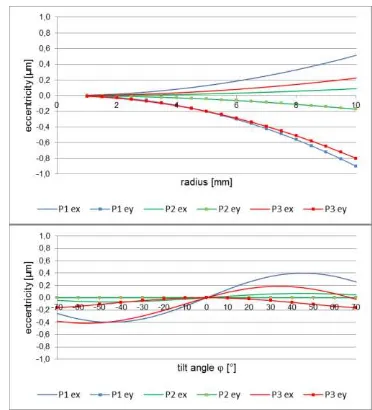
3.3.1 Industrial video camera: Figure 7 (top) shows the resulting eccentricity in x and y for the three representative points given in Table 1. Since the target plane is tilted by =20° about the X-axis, the eccentricity in y is larger than in x. Values for ex and ey decrease with longer imaging distance, i.e. smaller image scales. The largest value in this data set with about – 0.8µm is given for P3 and a target radius of 10mm. Assuming a practical target radius of 5mm (diameter = 10mm), the resulting eccentricities remain below 0.3µm (=1/20 pixel). Hence, for most applications with similar configurations, eccentricity can be neglected if the target radius is less than 5mm and the imaging distance is greater than 500mm.
Figure 7: Eccentricity in projection of circular targets as a function of target radius (left) and tilt angle (right, with r=5mm)
Figure 7 (bottom) displays the result of tilt angle variation for a target of 5mm radius. In this example the angle j is altered between –70 and +70 degrees while =0. The eccentricity ex behaves like a sine curve with a maximum between 45° and 60° depending on target position. For targets P1 and P2 there is no eccentricity ey since the points are located on the optical axis and is zero. P3 is located away from the optical axis and leads to sinusoidal eccentricities ex that are symmetrical with respect to the sign of j.
X Y Z scale amin amax bmin bmax
[mm] [mm] [mm] [px] [px] [px] [px]
P1 0 0 -500 62 2.7 26.7 2.5 24.7
P2 0 0 -1200 150 1.1 11.1 1.0 10.3
P3 250 200 -600 75 2.4 24.2 2.0 19.7
Table 1: Object point coordinates, imaging scale and resulting semi-axes for video camera setup
X Y Z scale amin amax bmin bmax
[mm] [mm] [mm] 1 : [px] [px] [px] [px]
P4 0 0 -500 21 8.0 79.9 7.4 73.9
P5 0 0 -1500 62 2.7 26.6 2.5 24.6
P6 1000 700 -600 25 9.8 97.6 4.7 46.7
Table 2: Object point coordinates, imaging scale and resulting semi-axes for SLR camera setup
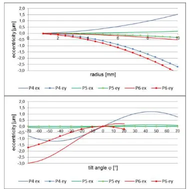
3.3.2 Digital SLR camera: Again three object points are investigated where two lie on the optical axis and one is located in the corner of the field of view.
The curves of Figure 8 show the same basic behaviour as those of Figure 7. However, for the closer object points P4, P6, a target radius of 10mm yields eccentricities of up to 3µm, and even 5mm targets show eccentricity values of about 0.8µm. For a 5mm target (Figure 8 right) possible rotations in j lead to significant eccentricities, e.g. up to 1µm (= 1/5 pixel) for P4 at
j=30°. For point P6 the target is not visible anymore if j exceeds +20°.
Figure 8: Eccentricity in projection of circular targets as a function of target radius (left, =20°, j=10°) and tilt angle
(right, with r=5mm)
The results above prove the well-known effect of eccentricity, hence the effect becomes larger with larger image scale, larger target radius and larger tilt angle between target and image plane. As a conclusion, the eccentricity in projection of flat circular targets should not be neglected. It should be noted that the effect creates a systematic image measurement error and cannot be compensated by multiple and highly redundant imagery. It should also be pointed out that the examples above do not describe worst case scenarios as they could appear for
wider imaging angles, e.g. using lenses with very short focal length and/or larger sensor formats. In those cases the resulting systematic errors will be even higher.
3.4 Eccentricity of spherical targets
Using the same input parameters as in the previous sections, the eccentricity effect of spherical targets is estimated. Since the effect does not depend on tilt angles between image and target plane, only sphere radius and target position in space are altered by simulation. Note that in practice, spherical targets are not usually available with diameters less than 5mm.
Figure 9: Eccentricity in projection of a spherical target at points P3 and P6 as a function of target radius (top), and for P1
and P4 as a function of exterior orientation angle j (bottom)
Figure 9 (left) shows the resulting eccentricity for a spherical target as a function of the radius. The targets correspond to point P3 in Table 1 (video camera) and P6 in Table 2 (SLR camera). The curves show the resulting values for ex and ey for both camera types. As with the flat target tests, the eccentricity for the SLR setup is larger than for the video camera due to the larger scale (smaller scale numbers in Table 2) and the larger
viewing angle. A sphere of radius 5mm leads to about 0.3µm displacement while a sphere of radius 10mm gives up to 11µm (2 pixels) for the SLR camera. Figure 9 (right) shows the eccentricity ex as a function of image tilt angle j of exterior orientation. Here the analysis is of points P1 and P4 which lie on the optical axis at j=0°. For a target with r=5mm a tilt of more than 20° results in an eccentricity of 0.3µm, reaching 1.6µm at 45° for the video camera and 1.8µm for the SLR camera. Note that one of the advantages of spherical targets is the wider angle of visibility so that tilt angles of 45° or more are realistic. The effect is even more relevant if targets of larger diameters are used, e.g. r=10mm in Figure 9 (right) where eccentricities of more than 1 pixel can occur for the SLR set-up.
As a conclusion, the use of spherical targets is even more critical in comparison with flat targets, with regard to eccentricity in projection. However, since the eccentricity does not depend on any angular orientation, as it is true for circular targets, it is possible to calculate the eccentricity as described above and use it as a correction for the measured target centre.
In addition, eccentricity of spherical targets has a radially symmetric behaviour. As shown in Figure 10, the displacement of image points is systematic. Hence, if a camera is calibrated by a point field that consists of the same spherical targets as for the actual application, it can be assumed that the effect of eccentricity in projection is mostly compensated by the parameters of radial distortion.
Figure 10: Eccentricity in projection of a spherical target with r=10mm
4. ECCENTRICITY IMPACT ON SPATIAL INTERSECTION
4.1 Imaging configurations
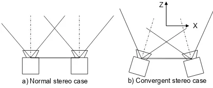
In many industrial applications, stereo or multiple camera setups are used to measure object points by space intersection. In those cases cameras are pre-calibrated and exterior orientation is either given by stable camera fixtures or by continuous re-orientation using control points. Figure 11 shows two typical camera setups that will be analysed in the following sections. A three-camera setup has been investigated in Luhmann (2014).
a) Normal stereo case b) Convergent stereo case X Z
Figure 11: Stereo camera scenarios
For an observed sphere, Figure 12 shows the principle effect of eccentricity on the calculated 3D point coordinates. Here the effect in x is illustrated because it is most critical for the x-parallax, hence for depth calculation. For cameras that are configured according to the normal case of stereophotogrammetry (Figure 11a), ex' and ex" have the same sign, hence the resulting X- or Y-coordinate is shifted while Z is almost unaffected. In contrast, for convergent imagery (Figure 11b) the sign of eccentricities is different, and a systematic x-parallax error occurs that results in an object error mainly in Z.
e'C' E' C
O'
target or tangential plane
image plane
e'C' E'
O" DX
E
X Z
e" C"
E" C
O'
target or tangential plane
right image e'
C'
E'
O"
left image
E DZ
X Z
Figure 12: 3D point errors caused by eccentricity in projection for parallel images (top) and convergent images (bottom)
As a representative configuration, a stereo camera with two industrial video cameras as specified in the previous section is investigated. Using a stereo base of b=300mm two variants are simulated: a) a normal case configuration with parallel optical axes and b) a convergent configuration with j=±10°. These setups are typical for many applications in medicine, robotics or photogrammetric machine control (Luhmann et al. 2013).
In order to estimate the theoretical accuracy level for a stereo configuration, a Monte-Carlo simulation has been applied. It
can be shown that a normally distributed image measuring noise of 1/20 pixel (= 0.3µm) leads to RMS values (1 sigma) of 0.02mm in X,Y and 0.14mm in Z for object points at a distance h=1200mm (height-to-base ratio h/b=4:1). For points at a distance of h=300mm (h/b=1) a theoretical precision of 0.004mm in in X, Y and Z can be expected.
4.2 Spatial intersection
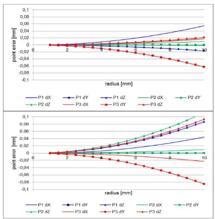
4.2.1 Stereo images: The following investigations are based on the sequence of calculations as described in the third section added by spatial intersection using the image ellipse centres. For the case of circular targets and parallel viewing directions, Figure 13 (top) illustrates the resulting 3D coordinate errors for the points of Table 1 as a function of varying target radius for the video camera setup. The target plane is tilted by =20° and
j=10° (and note that eccentricity would not occur at =0 and
j=0). As expected from Figure 12, deviations in X and Y are significantly higher than in Z. The maximum error is given by P1 with –0.06mm in Y at r=10mm. For a practical target radius of 5mm the resulting errors lie below 0.02mm.
Figure 13: 3D point errors as a function of circular target radius for normal case (left) and convergent stereo case (right)
Figure 13 (bottom) shows the 3D coordinate errors as a function of varying target radius in the case of convergent images (j1=– 10°, j2=+10°). Here the target plane is parallel to the XY plane of the object coordinate system. For points P1 and P2, which lie in the middle between both cameras (X=0), only a deviation in Z can be observed. It ranges up to 0.1mm for large targets (r=10mm). Since the error in Z is almost equal for P1, P2 and P3, it can be assumed that the effect of quadraticly increasing stereoscopic Z error, which depends on the height-to-base ratio, is compensated by the decreasing eccentricity effect at longer distances. For point P3, which lies to the right of the cameras (X=250mm), errors in all coordinate directions can be observed. For a practical target radius of 5mm, the resulting Z error is in the order of 0.03mm which should not be neglected if high point accuracy is required.
Figure 14: 3D point errors as a function of spherical target radius for normal case (left) and convergent stereo case (right)
Figure 14 shows the errors of spatial intersection caused by eccentricity of a spherical target. For the normal stereo case, point P1 shows larger errors in X than in Z, while Y is calculated correctly. The same effect occurs for P2 but with smaller values since the point is further away from the cameras. P3 shows errors in all directions. In general, 3D point errors of up to 0.03mm must be expected for a target radius of 5mm. With larger spheres the error easily reaches critical limits, e.g. 0.06mm at r=10mm.
For convergent images, the error behaviour is different. Here the errors in Z are larger than in X for P1 and P2 as expected from Figure 12. In general, resulting 3D point errors are almost twice as high as for the normal case of stereophotogrammetry. For 5mm targets, errors remain below 0.03mm but easily reach 1/10mm for r=10mm.
4.3 Length measurement error
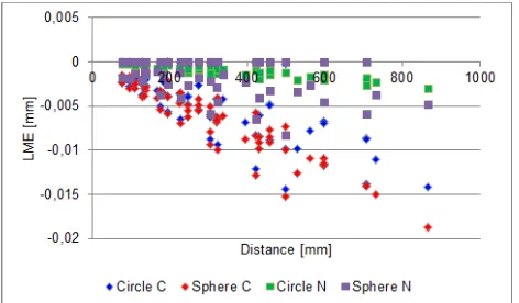
In order to estimate the impact of target eccentricity to the quality of length measurements, two examples have been investigated. Based on a stereo setup with convergent cameras as given in section 4.1, an arrangement of 7 scale bars has been simulated that follows the recommendations of the German guideline VDI 2634. Each scale bar consists of five given points, hence up to different 10 distances are defined per scale bar. From all 7 scale bars a total of 35 object points and 70 individual distances are given. The cube of scale bars covers a volume of about 500 x 500 x 500 mm³.
Figure 15 shows the result of length measurement errors (LME) by comparing measured distances to reference distances. For all tested configurations, a clear dependency on the length of the distance can be seen and the measured distances appear too long, hence all LME have a negative sign. For the convergent camera setup (Circle C, Sphere C) it can be observed that maximum LME of more than 0.015mm occur which are caused only by target eccentricity. Spherical targets cause higher LME than circular targets which is in accordance to the results of section 4.2.
Figure 15: Length measurement errors for VDI set-up of circular targets
In the case of parallel viewing directions (normal case of stereo photogrammetry) the LMEs are significantly smaller (Circle N, Sphere N). The maximum LME reaches 0.007mm, hence below a significant level. It can be assumed that the points of the scale bars are subject to similar systematic point errors that are compensated with respect to the distance between them.
For the presented example it can be shown that the effect of target eccentricity does not affect length measurements to a higher amount. The systematic negative LME is presumably caused by the very symmetric arrangement of targets and the effect that the eccentricities in image space lead to errors in Z and consequently to a scaling effect in object space.
5. SUMMARY AND OUTLOOK
The investigation has shown that eccentricity in images of circular and spherical targets reach a significant amount under practical conditions. With respect to increased accuracy demands and smaller camera pixels the effect has to be considered in measurement. It can be proved that spherical targets show larger eccentricities and resulting object point errors than circular targets. While the eccentricity of spherical targets can be calculated for known target diameters, flat circular targets can only be measured without eccentricity if the normal vector of the target plane is known, which can be calculated from stereo or multi-image configurations.
A general solution to the problem of eccentricity in projection of circular targets is given by a rigorous calculation of the original circle in 3D space. Several approaches have been published , e.g. Kager (1981), Andresen (1991), Schneider (1991), Otepka & Fraser (2004) or Wrobel (2012) who all found solutions for the determination of 3D circle centres from image points.
REFERENCES
Ahn, S. J., Kotowski, R., 1997. Geometric image measurement errors of circular object targets. In Gruen/Kahmen (eds.): Optical 3D Measurement Techniques IV, Wichmann, Heidelberg: 463–471.
Andresen, K., 1991. Ermittlung von Raumelementen aus Kanten im Bild. Zeitschrift für Photogrammetrie und Fernerkundung, Nr. 6: 212–220.
Bethmann, F., Luhmann, T., 2010. Least-squares matching with advanced geometric transformation models. International
Archives of Photogrammetry, Remote Sensing and Spatial Information Sciences, Vol. 38, Part 5: 86–91.
Clarke, T. A., 1994. An analysis of the properties of targets used in digital close range photogrammetric measurement. Videometrics III, SPIE Vol. 2350, Boston: 251–262.
Dold, J., 1997. Ein hybrides photogrammetrisches Industriemeßsystem höchster Genauigkeit und seine Überprüfung. Dissertation, Heft 54, Schriftenreihe Studiengang Vermessungswesen, Universität der Bundeswehr, München.
Fraser, C. S., 1992. Photogrammetric measurement to one part in a million. Photogrammetric Engineering and Remote Sensing, 58(3): 305–310.
Förstner, W., 1982. On the geometric precision of digital correlation. International Archives for Photogrammetry and Remote Sensing, Vol. 26/3: 176–189.
Förstner, W., Gülch, E., 1987. A fast operator for detection and precise location of distinct points, corners and centres of circular features. ISPRS Intercommission Workshop on „Fast
Processing of Photogrammetric Data“, Interlaken, pp. 281-305.
Gruen, A., 1985. Adaptive least squares correlation – a powerful image matching technique. South African Journal of Photogrammetry, Remote Sensing and Cartography, 14 (3): 175–187.
Kager, H. 1981. Bündeltriangulation mit indirekt beobachteten Kreiszentren. Geowissenschaftliche Mitteilungen der Studienrichtung Vermessungswesen der TU Wien, Heft 19.
Luhmann, T. (2010). Close range photogrammetry for industrial applications. ISPRS Journal for Photogrammetry and Remote Sensing, Vol. 64/3: 558–569.
Luhmann, T., Robson, S., Kyle, .S., Boehm, J., 2013. Close-Range Photogrammetry and 3D Imaging. 2nd ed., de Gruyter, Berlin, 683 p.
Luhmann, T., 2014: Eccentricity in images of circular and spherical targets and its impact on spatial intersection. The Photogrammetric Record (to appear).
Majahan, V. N., 1998. Optical Imaging and Aberrations. Part 1: Ray Geometrical Optics. SPIE Press, Bellington, USA.
Otepka, J. O., Fraser, C. S., 2004. Accuracy enhancement of vision metrology through automatic target plane determination. International Archives of Photogrammetry, Remote Sensing and Spatial Information Sciences, 35(B5): 873–879.
Ouellet, J.-N., Hébert, P., 2009. Precise ellipse estimation without contour point extraction. Machine Vision and Applications, Vol. 21, Issue 1, pp. 59-67.
Robson, S., Shortis, M., 2007. Engineering and manufacturing. In Fryer et al. (eds.): Applications of 3D Measurement from Images. Whittles Publishing, Caithness: 65–101.
Schneider, C.-T., 1991. Objektgestützte Mehrbildzuordnung. Dissertation, Deutsche Geodätische Kommission, C, Nr. 375.
Wrobel, B. P., 2012. Kreismarken in perspektiver Abbildung – im Bild und im Bündelblock. Photogrammetrie-Fernerkundung-Geoinformation, 16(3): 221–236.