OPTO-ACOUSTIC DATA FUSION FOR SUPPORTING THE GUIDANCE OF
REMOTELY OPERATED UNDERWATER VEHICLES (ROVs)
F. Bruno1, A. Lagudi1, G. Ritacco1, M. Muzzupappa1, R. Guida2
1 Dept. of Mechanical, Energetics and Management Engineering, Università della Calabria, Rende (CS), Italy – (fabio.bruno, antonio.lagudi, gerardo.ritacco, maurizio.muzzupappa)@unical.it
2
Whitehead Sistemi Subacquei S.p.A., Pozzuoli (NA), Italy – [email protected]
Commission V
KEY WORDS: 3D opto-acoustic camera, optical and acoustic data fusion, stereovision system, system calibration, ROV guidance
ABSTRACT:
Remotely Operated underwater Vehicles (ROVs) play an important role in a number of operations conducted in shallow and deep water (e.g.: exploration, survey, intervention, etc.), in several application fields like marine science, offshore construction, and underwater archeology. ROVs are usually equipped with different imaging devices, both optical and acoustic. Optical sensors are able to generate better images in close range and clear water conditions, while acoustic systems are usually employed in long range acquisitions and do not suffer from the presence of turbidity, a well-known cause of coarser resolution and harder data extraction. In this work we describe the preliminary steps in the development of an opto-acoustic camera able to provide an on-line 3D reconstruction of the acquired scene. Taking full advantage of the benefits arising from the opto-acoustic data fusion techniques, the system was conceived as a support tool for ROV operators during the navigation in turbid waters, or in operations conducted by means of mechanical manipulators.
The paper presents an overview of the device, an ad-hoc methodology for the extrinsic calibration of the system and a custom software developed to control the opto-acoustic camera and supply the operator with visual information.
1. INTRODUCTION
During the last few years, there has been growing interest for the development of efficient methodologies and systems in the underwater research area, in order to deal with the challenging problems of monitoring, survey and data gathering.
In the field of cultural heritage,
the scientific community and the international Cultural Heritage safeguarding bodies have established the need to promote, protect, and preserve, possibly in-situ, the submerged artefacts and sites.
The CoMAS project, started in 2011, aims to develop new materials and technologies for supporting the restoration, conservation and documentation of underwater cultural heritage. The project goal is the definition of a conservation methodology that includes several stages: documentation, cleaning, restoration, maintenance and monitoring.
One of the most challenging aspects of this project is the set-up of a special ROV (Remotely Operated Vehicle) devoted to the monitoring, routine cleaning (through the use of a custom mechanical manipulator), and 3D mapping of the submerged archeological structures. These specific tasks require the accurate localization of the vehicle within the operational environment and, above all, a clear representation of the underwater scene in presence of low visibility conditions. ROVs are usually equipped with different imaging devices both optical and acoustic. The acoustic systems typically give good results in long-range acquisition and do not suffer from the water turbidity, but the resulting data are affected by low resolution and accuracy. The optical systems, in contrast, are more suited for close-range acquisitions and allow for gathering high-resolution data and target details, but the results are constrained by a limited visibility range.
Hence, the fusion of data captured by these two types of systems stands as a promising technique in underwater applications, as it allows for compensating their respective limitations. Since the two categories of sensors are based on different physical principles, they provide, in general, different information of the scene to be acquired, and different methods
are employed to process the data. Therefore, the integration of the two types of data gathered from these sensors is a very promising and interesting field that calls for new solutions. Despite the difficulty of combining two modalities that operate at different resolutions, technological innovation and advances in acoustic sensors have progressively allowed for the generation of good-quality high-resolution data suitable for integration, and the related design of new techniques and systems for underwater scene reconstruction.
The aim of this work is to describe the preliminary steps in the development of an opto-acoustic camera able to provide on-line 3D reconstructions. Taking full advantage of the benefits arising from the opto-acoustic data fusion techniques, the system was conceived as a support tool for ROV operators during the navigation in turbid waters or in operation conducted by means of mechanical manipulators. The operator will be able to choose the most suitable visualization technique (optical, acoustic) according to the working conditions or, if needed, to fuse both of them in a single image where the missing parts of the acquired optical data are covered by the acoustic acquisitions. The remainder of this paper is organized as follows: Section
2
presents the state-of-the-art concerning the integration of optical and acoustic sensors in the field of underwater applications, and the solutions adopted to fuse the data. Section 3 deals with the system configuration and the hardware specifications of the sensors that constitute the opto-acoustic camera. In Section 4 we formalize the extrinsic calibration problem of the system and provide a methodology to solve it. The conclusive section presents the main features and a first prototype of the user interface.
2. RELATED WORKS
community, so various areas image process In the field of merge optical 2000). In this merge optica (acquired thr resolution qua fusion is achie across the two warp, by warp by the same co A system for terrain through camera and ra (Kunz and S optimization, framework (√ trajectory, the frame. Matche as images of submap match by linking R trajectory. The the ROV’s tra sensors, and th observations matches, in calibration of position and specialized no A further exa acoustic senso work focused large area ma acoustic sens understanding during the na obtained from (Coda Echosc data with resp After some pre with respect to in this case) u (Besl et al., 19 means of an a the poses of observed obje and the acous use positioning Although ver drawback of r the calibration linking the p domain and a Finally, we ha stereo reconstr which aims to composed by order to impr waters. Due to acoustic syste the two views in the acoustic image lies on point in the op
o that data fusio such as sens sing (Khaleghi e f underwater app and acoustic s work, simple fi al photomosaic rough a penci antitative opto-a eved by manual o representation ping the photom orresponding po
automatically h the fusion o ange data from
Singh, 2013). square root inf √SAM) to simu e map, and th ed visual featur f 3D landmar hes are used to i ROV poses from
e system is ini ajectory, as me
hen adds facto and constraint an incrementa
the navigation orientation i odes in the pose ample of tight ors is presented
on local area i aps. In this wo sors is propo g of the underw avigation. The m a single optica ope) is obtaine pect to a well-kn
e-processing st o a known mod using the Iterat 992), while the algorithm devel both sensors a ect, the relative stic camera can g and motion sy ry interesting, elying on a CA n of the system resented metho specific class o ave to mention ruction, propos o apply the epi an optical cam rove the accura o the asymmetr m, the epipola s. The derived c image, the rel a conic section ptical image lies
on systems are sor networks, r
et al., 2013). plications, one sensors is repor finite element w cs with micr il beam sonar acoustic maps lly identifying c ns and then, us mosaic onto the oints.
building 3D m f visual data a
a multibeam s The system formation smoo ultaneously so he camera loca es are treated w rks, while mu
impose the rela m distinct trac itialized with a easured by the r nodes represe s induced by al fashion. In n sensors and t
is enabled th graph itself.
integration be d in (Fusiello an
imaging rather ork, the integra osed in order water scenes an
integration of al camera and a
d by geometric nown model of eps, the acousti del of the object tive Closest Po e optical alignm loped by Lowe are calculated e pose between n be estimated ystem equipme the presented AD model of the m, which may n
odology to a of objects. n a new paradig sed in (Negahda ipolar geometry mera and a 2D s acy of 3D reco rical projection ar geometry, in equations show lative correspon n. Moreover, th s on specific tri
now widely us robotics, video of the first effo rted in (Singh e warps may be us robathymetric
r), obtaining of the seafloor corresponding p sing a finite ele e new mesh de maps of under acquired by a s sonar is present uses pose g othing and map olve for the R
ation in the R within the pose g
ltibeam bathym ative pose const
cklines of the graph that cap onboard navig enting visual fe multibeam su
this solution the extrinsic ca hrough the us etween cameras nd Murino, 200 than the creati ation of optica r to improve nd assist ROV video and 3D a 3D acoustic ca cally registering f the observed s ic data are regis t acquired (an o oint (ICP) algo ment is perform (Lowe, 1991). with respect t n the optical ca
without the ne nt.
d solution has e object acquire ot be available
specific applic gm of opto-aco aripour et al., 2 y to a stereo sy sonar (DIDSON onstruction in t
models for an this case, diffe w that for each ndence in the o he matching of gonometric cur
sed in points ement efined rwater single ted in traints dive ptures gation eature ubmap
pilots D data
amera g such scene. stered oil rig orithm med by cation oustic 2009), ystem N), in turbid opto-fers in
point optical f each
extrinsic calibr n performed by
acterized by re n manually asso cameras were e
minimizes the cal and acoustic
3. S
his section we ex t we describe ware specificat ustic camera, i. cal camera, resp
System Conf
proposal aims roviding an on he scene to be ac
opportunities o pical application
ROV operator oration / maint erwater manipu es of the interv lay modes wou be performed, ultaneously to r on techniques.
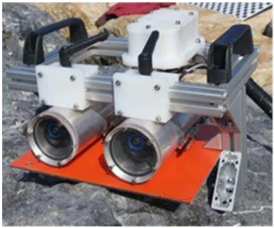
ure 1. Scheme o d-Of-Views of en) and of the 3
which concern eo camera, con sed in custom-m
he laboratories rgetic and M abria. Instead, t eloped ad-hoc f tehead Sistemi ive position of acoustic one w V set-up in ord d-Of-Views (FO
ration of the op y using image elevant optical ociated. Theref estimated throu e distances bet c matching proje
YSTEM DESC
xplain the setup the system tions of the sen .e. the 3D aco pectively.
figuration
at realizing an -line optical an cquired. offered by this k
n scenario, it co during the nav tenance operat ulators. The o ention, may det uld be more sui or may als represent both
of the system’s the optical cam D acoustic cam
ns the optical nsisting of 2 u made waterproo s of DIMEG Management E
the 3D acoustic for the CoMAS
Subacquei S.p the stereo opti as defined duri der to ensure th OVs) (Figure 1)
ptical and acous es of a planar l acoustic feat fore, the relativ ugh an optimiza tween 3D reco
ections.
CRIPTION
p of the propose configuration nsors that cons oustic camera
opto-acoustic c nd acoustic 3D
kind of system ould be used as vigation in turb tions conducted operator, durin etermine which itable for a spe so decide to
data types by
s proposed con meras in stereo mera (red).
component of ultra-compact d of cases, has b (Department o Engineering),
c camera is a S project at the p.A. in Pozzuoli ical subsystem ring the plannin
he maximum o ).
stic camera has r grid (target), ures that have ve positions of ation algorithm onstructions of
ed system. and then the titute the opto-and the stereo
camera capable reconstruction are endless. In s a support tool id waters, or in d by means of ng the various one of the two ecific operation display them means of data
nfiguration with o configuration
3.2 3D acou
The 3D acous angular resolu 2).
It consists of acoustic units unit), and ano the beamformi The transmissi spaced linear receiving sec logarithmically The acoustic suitable direc coming from a The beamform digital level th algorithms in acoustic echos The key techn table 1.
Frequency
Number of b
Maximum r
Minimum ra
Update Rate
Beam spacin
Angular cov Dimensions (max diam., Weight
Supply volta
Power consu
Interface
Table 1. Tec
ustic camera
stic camera is a ution images of
Figure 2. 3D
f two distinct for transmittin other one for pr
ing process. ion section of th
array made o tion is made y spaced linear unit generates ctions, and ac a target in the fo ming section pro hrough beam-fo n order to det
s (range and ang nical specificati
beams
range
ange
e
ng
verage
, min diam., l)
age
umption
chnical specific
a custom system f the acoustic
D acoustic came
subsystems: ng and receivin
rocessing the s he acoustic unit of 40 analog c of 256 chann r arrays.
beams which cquires the ba ocused region. ocesses the inc orming and bea tect the polar gle).
ions of the syst
700 KHz 41x84x61 Focusing d Focusing d Up to 1 Hz 1˚ 60˚ x 40˚ 410 mm, 26 27 Kg (air) 12 VDC 200 W ca. Gigabit Eth
cations of the 3D
m that provides environment (f
era.
one containing ng signals (TX ignals to be us t is a logarithm channels, whil nels arranged
focus the ener ackscattered si oming signals am-power evalu
coordinates o tem are present
total
distance + 30 cm distance - 30 cm
60 mm, 287 mm , 5Kg (water)
hernet
D acoustic came s high
figure
g the / RX sed in mically le the
in 4 rgy in
ignals at the uation of the
ted in
m m
m
era.
3.3
The resea Univ phot Bian
The hous The 23G4 6.26 rate Edm Sinc unde wate ensu came solut refra easie appr The guar In ta the d
Wo
FO
Dim
Dim
We
Tri
Sup
Pow
Inte
Tab
Stereo optica
proposed stere arch activity co versity of Cala
ogrammetry, b nco et al., 2013)
Fig
system is comp sed in custom-m digital cameras 445 with a CC x 5.01 mm, a of 30 fps. The mund Optics 1.8
e the two digit erwater environ erproof housing ure efficient he
era housing (d tion leads to a r action of the a er. The camer
opriate support layout of the antee the maxim able 2 we have device.
orking distance
V (water) (dia
m. point cloud
mensions (w x h
eight
gger
pply voltage
wer consumpti
erface
ble 2. Technical
al camera
eo optical came onducted at the abria in the fie oth passive an .
gure 3. Stereo op
posed of two ca made waterproo s are two ultra-c CD (Charge Co
resolution of 1 e devices are a
mm wide-angl al cameras wer ment, we have s. The body is m eat dissipation, dome port) is m
reduction of the air-water interf ra is fixed w , that also work stereo configu mum FOV with reported the ma
e (min.) 1 m
g.) 70° 200
h x l) 210 2.6 Yes 11 –
on 4.8 Gig
l specifications
era is the resul he DIMEG dep eld of the und nd active (Brun
ptical camera.
ameras in stereo of cases (figure
compact Imagi oupled Device)
280 x 960 pixe also equipped le lenses. re not thought
designed and c made in alumin , while the fl made in polyc e angle of view rface, but its c within the cas
ks as heat sink. uration has bee h a minimal wor main technical sp
m (baseline 105 °
0.000 ca 0 x 100 x 207 m
Kg (air), 1.2 K s
– 13 VDC W ca. gabit Ethernet
of the stereo op
lt of an intense partment of the derwater stereo no et al., 2011;
o configuration, 3).
ngSource DFK sensor size of els and a frame with a pair of for their use in constructed two num in order to at port of the carbonate. This w caused by the construction is se through an en designed to rking distance. pecifications of
mm)
mm Kg (water)
ptical camera. e e o ;
4. EXTRINSIC CALIBRATION OF THE SYSTEM
During the development of the proposed 3D opto-acoustic camera was the alignment of the optical and acoustic 3D data, defined as sensor calibration problem, which allows data from one sensor with the corresponding data of the other sensor. Data alignment, that is, their transformation from each local frame into a common reference frame for both sensors, is of critical importance for the successful deployment of the opto-acoustic fusion system, since the 3D data generated by such sensors are so different from each other that they should be precisely matched in order to detect the spatial coordinates of a given point belonging to an object in both representations. Up to now, the works presented in literature concerning the integration between several types of sonar (single beam sounder, multibeam, 3D acoustic camera) and optical cameras adopt a sensor fusion approach, which is mapping-oriented, according to the classification proposed in (Nicosevici et al., 2008). This means that the data acquired from the two sensors are described through geometric relationships (position and orientation), and the data fusion is performed by means of geometrical correspondences and registration.
The alignment of 3D data is usually solved by performing the extrinsic calibration of the integrated system, i.e. by searching for the fixed - but unknown - rigid transformation which relates the local reference frame of the stereo optical subsystem with that of the acoustic camera, thereby obtaining the relative pose (position and orientation) between the two sensors.
Now, let us assume that the two cameras have already been calibrated independently. In particular, with regard to the stereo optical system, the assumption is that both the intrinsic parameters of each optical camera (focal length, principal point, optical distortions and skew) and those of the extrinsic stereo pair (relative position between the two reference frames) have been determined. Downstream of this calibration process, it is possible to know the 3D coordinates of any point of the scene acquired by the optical subsystem with respect to its local reference frame (typically attached to the left camera of the stereo pair).
Therefore, assuming that a point , , of the optical reference frame corresponds to a point x , y , z of the acoustic reference frame, the rigid transformation that relates the two coordinate systems may be expressed as:
(1) where R = 3 x 3 orthonormal rotation matrix from the acoustic camera to the stereo optical camera reference frame
t = 3D translation vector from the acoustic camera to the stereo optical camera reference frame
Equivalently, indicating with and the homogeneous coordinates of the points and respectively, the aforementioned relation can be expressed as:
p t p (2)
where = 4 x 4 homogeneous transformation matrix from the acoustic camera to the stereo optical camera reference frame
Therefore, our goal is to develop a methodology for the calculation of the extrinsic parameters R and t, which define the
orientation and the position of the acoustic subsystem against the optical one, respectively.
Usually, the calibration methods are highly dependent on the sensors that compose the system and especially on the type of data they provide. In our case, the particular nature of the data acquired by the systems (3D point clouds) makes it possible to implement a methodology for extrinsic calibration based on a "direct" computation of the rigid transformation matrix that relates the reference systems associated with the optical and acoustic sensors. This is achieved through a simple registration of each pair of optical and acoustic 3D point clouds of a planar pattern, which is used as a target in the calibration procedure and acquired in different poses. Finally, the ability to obtain multiple estimates of the transformation matrix allows for implementing an appropriate optimization technique, in order to obtain more accurate results.
The implemented methodology is composed of two separate data-processing threads that are related to the two sensory channels, which eventually merge in the last stages of the proposed solution.
Starting from the synchronous acquisition of the n poses of the calibration panel during the early stage of the process, the entire methodology is aimed to obtain n pairs of 3D point clouds, where the n-th pair is formed by the optical , and the acoustic , 3D point clouds, in order to calculate, by means of coarse and fine registration algorithms, n estimates , of the rigid transformation matrix. At the end of the process, the final transformation matrix ∗ is obtained by processing the dataset composed of n transformation matrices , obtained downstream of the previous registration stage.
4.1 Acoustic image processing
The 3D image provided by the acoustic camera can be corrupted either by false reflections caused by the secondary lobes of the receiving array or by the noise present in the acquisition phase of the backscattering signals. The latter is modelled as speckle noise. The secondary lobes are responsible for the blurring of the object, while the speckle noise causes a low response or no response at all within the object itself.
So it is evident that the operations of filtering (noise reduction and the elimination of possible outliers) and segmentation (differentiation of objects and background in the observed scene) are to be considered as preliminary and mandatory steps for the execution of all fusion algorithms to be applied to this specific type of data (Murino et al., 2000a).
While in literature there are a number of algorithms for filtering and segmentation with variable results and degrees of automation (Murino, 2001b)
,
the solution adopted in this calibration method for the processing of the acoustic 3D point clouds representing the calibration panel in its different poses, provides for a completely manual filtering and segmentation procedure, performed through the open source software CloudCompare (CloudCompare, 2014), as the implementation of an automated procedure would require further, more focused research.4.2 Optical stereo images processing
This subsection describes the procedures for the creation of a 3D point cloud representing the optical calibration panel in its different poses, starting from the acquisition of a pair of stereo images.
4.2.1 Image enhancement Underwater images are
limited visibili channel) and n quality of the reconstruction Regarding th solution make based on the al., 1992) an procedure (HI
4.2.2 Ster
needed to co (focal length, tangential dist (translation an system) of the are computed Toolbox for M
4.2.3 Che
the calibration through well-order to obtain each pose assu The 3D reco (OpenCV 201 particular, the the stereo pair of the stereo disparity map the product of the calibration
4.1 Coarse
This subsect methodology t the unknown r Considering th point clouds, composition o fine registratio Taking as a r stereo optical out through tw
1. Calculatio the acoust that the Z the optical
2. Alignment an automa from an es clouds, de (assuming As a resul matrix For what c implementatio Closest Point
, , align
transformation Downstream transformation
ity range, color noise. All these e results obtain n technique (Ga he proposed c
es use of a me technique of H nd on a subs
ST).
reo optical cali
mpute the intr coordinates o tortions, pixel nd rotation wi e camera and th d using the Matlab (Bouguet
ckerboard 3D
n process, the known techniq n the 3D point umed during the onstruction was 14) and Libelas OpenCV libra r, while Libela matching algo . Finally, the 3 f the reprojecti n process and th
and fine regist
tion describes that allows for rigid transforma he n-th pair , the associat of transformati on algorithms.
eference system camera, the co wo operations: on of , by
tic camera loca axis represents l system; t of the pair of atic algorithm im stimate of the ce etermines the tr g that the rotatio lt of this opera
, .
concerns the on in CloudCom
algorithm (IC ned in the pre n matrix , . of the previou n matrix ,
, ,
r attenuation (p e issues have a ned in the app
llo, 2013). calibration me ethodology of Histogram Stre sequent manua
bration A cali
rinsic paramete of the principa
size) and the ith respect to he stereo system
well-known C t, 2013).
D reconstructio
acquired imag ques of stereo
clouds of the e acquisition sta s carried out s (Geiger et al. ary was used fo as was used for orithm and the 3D point cloud
on matrix obta he disparity map
tration
the steps obtaining the n ation matrix.
, , of acou
ted , is ions obtained m the local ref oarse registratio
means of a m al reference fra s the depth of th
3D point cloud mplemented in enter of gravity ranslation vecto on matrix R is u ation, we obtain
step of fin mpare of the w CP) has been evious step, in
us operations, is obtained as (
,
articularly in th strong impact o plication of an ethod, the ad image enhance tching (Gonzal al color retou
ibration proced ers of each ca l points, radia extrinsic param
a world coord m. These param Camera Calibr
on Downstrea
ges were proc photogrammet calibration pan age.
using the Ope ., 2011) librarie or the rectificati
r the implement e generation o d was determin ained downstrea
p itself.
of the calibr n estimates
ustic and optica determined through coarse ference frame o on stage was ca
manual orientati ame, in such a he scene, in line
ds , , thr CloudCompare y of the two 3D or t that relates unitary).
n the transform
ne registration well-known Iter
applied to the order to obtai the unknown (figure 4):
,
he red on the ny 3D dopted
ement lez et uching
dure is amera al and meters
dinate meters ration
am of cessed try in nel for
enCV es. In ion of ntation of the ned as am of
ration
, of
al 3D as a e and of the arried
ion of mation
n, an rative e pair
ure 4. Sequence
Statistical pr
method of statis r to estimate th rices , obta fine registratio ds.
proposed soluti TLAB, which sformation mat rices included in
algorithm opera for each , , acoustic point corresponding 3 for each pair points of the op of the acoustic 3 calculates a selects , a assumes as
, .
5. CAM
gned with the a niques current osed system is nstruction of th cerning the aco lution image by Detection mo isotropic scan coarse positio Classification acoustic came fine scan of i is automatical the system de manually, by
the other hand alizing the acqu
e of transformat matrix
ocessing of the
stical processin he rigid transfor ained downstre on applied to ion is basedon h automatical trix ∗, by n the dataset.
ates in the follo it applies this t clouds, in or 3D optical point
, , , the me
ptical 3D cloud 3D cloud is calc as the mean of as the minimum
∗ the transform
MERA CONTR
aim of integratin tly available
able to provide e acquired scen oustic subsystem y working in tw
de: in this mod n of the scene on of a target; n mode: after
era switches to ts FOV (60˚ x lly activated wh etects a target setting the focu
d, the stereo o uired scene thr
tions for compu x.
e transformati
ng has been im ormation matrix
eam of the oper pairs , , n an algorithm i
lly determine selecting it fr owing way:
transformation rder to align t nt clouds , ; ean distance d and the corres
culated;
, ;
m value of ; mation , co
ROL SOFTWA
ng the most rec in scientific de an on-line op
ne.
m, it provides wo different mod dality the syste
e in order to
the target iden this modality 40˚). The class hen, in the prev at a range les us distance.
optical subsyste rough a digital
uting the ,
on matrices
mplemented in x ∗ from the ration of coarse of 3D point implemented in es the final rom the ,
to the , 3D them with the
, between the
sponding points
orresponding to
ARE
cent data fusion literature, the pto-acoustic 3D a high angular dalities: em performs an
determine the
ntification, the and performs a sification mode vious modality, ss than 2 m or
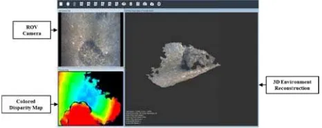
stereo pair, an using different A custom softw of the image d easily interpre It was concei following requ 1. a customiz A first prototy The system is modes. In this one screen, or information is the ROV opera For example, depth of the sc
Figur
Figure 6.
In this work development provide an underwater sc optical camera installed on a by the operato or in close ran
nd also to prov t stereo matchin ware is being d devices and for etable representa
ived and desig uirements:
zable interface on according to s;
xibility such tha main paramete cope with the er environment. ype of the user i s able to switc s way, 2D and 3 r in suitable dis s enhanced thro ator during spe
Figure 6 show cene is coded th
re 5. Prototype o wi
. Display windo RG
6. CON
, we have pr of an opto-ac on-line 3D r cene.The syste a and 3D acou ROV in order or during the na nge manipulatio
vide an on-lin ng algorithms. developed for su
r providing RO ation of the visu gned with the
to manage and different user p
at the operator ers of the opto variable cond
interface is show ch between di 3D information
splay windows ough additional cific work activ ws a display w
hrough a RGB s
of the user inter indow layout.
ow with depth m GB scalar field.
NCLUSION
resented a firs coustic camera reconstruction
m is composed ustic camera, an to improve its avigation in turb on operations. I
e 3D reconstru upporting the co OV operators wi ual information aim of meetin
d organize the v profiles and wo
is able to set, in o-acoustic came itions typical o
w in figure 5. fferent visualiz
can be display in which the v l data that may vities. window in whic
scalar field.
rface and contro
map coded throu
st step toward a, which is ab of the exp d of a custom s nd is designed s control capab bid water cond n order to perfo
uction ontrol ith an n. ng the
visual orking
n real era in of an
zation yed on visual y help plored
stereo to be bilities ditions form a
ect sensor fusi ed to determine reference system
osed. The cali ern as a target, w
ont of the opto ds provided by wo-step proces rithms and the stical processin developed a pro ustic camera an visual informati software allow verify its usab ly interpretable
7. AC
work has been PON01_02140 C’ 2007/2013 (
, P. J., & McKa hapes. In: Robot ety for Optics a nco, G., Gallo,
parative analys erwater 3D rec itzerland), Vol. guet. Webpa e 2014). no, F., Bianco
onale, A. V., 2 eo vision for un
hotogrammetry udCompare. W 4).
ello, A., and M visualization gration. Visualiz nsactions on, 10
o, A., 2013. In nstruction of Cu ger, A., Roser, e stereo match 8. Springer Ber zalez R.C., a essing. Addison leghi, B., Kham 3. Multisensor Information Fus
z, C., and Sing visual infor cles. Journal of
ion, an extrins e the rigid trans ms associated w ibration was c which has been o-acoustic syste the two camer ss based on c en the final ma
g.
ototype of the so d is able to pro on supplied by wed us to perfo bility. It also pr
representation
CKNOWLED
n partially suppo 0), financed by (D.D. Prot. n. 0
REFEREN
ay, N. D., 1992 tics-DL tentativ and Photonics.
A., Bruno, F. is between acti onstruction of 13, N.8, pp. 11 ge. http://ww
o, G., Muzzup 011. Experimen nderwater 3D r
and Remote Se Webpage http://
Murino, V., 2004 n by optica zation and C 0(6), pp. 625-63 nnovative meth ultural Heritage M., and Urtasu ing. In: Compu rlin Heidelberg. and Woods R
n-Wesley, Read mis, A., Karray data fusion: A sion, 14(1), pp.
gh, H., 2013. M rmation using f Field Robotics
sic calibration sformation mat with the two sen conducted by u n positioned in em. The two se ras have been a coarse and fin atrix was obtai
oftware that co ovide and mana
the system. orm initial tests provided the op of the visual in
DGEMENTS
orted by the Pro y the MIUR u 1/Ric. 18.1.201
NCES
. Method for re ve (pp. 586-606
., Muzzupappa ive and passive f close-range ob 1007-11031. ww.vision.calte
pappa, M., Ba ntation of struc reconstruction. ensing, 66(4), p /www.danielgm
4. Augmented s al and aco Computer Gr 36.
hodologies for e, PhD Thesis. un, R., 2011. E uter Vision–AC
. Map building f g autonomou s, 30(5), pp. 76
methodology, trix that relates nsors, has been using a planar different poses ets of 3D point aligned through ne registration ined through a ntrols the opto-age the 2D and s on the system perator with an nformation.
oject ‘CoMAS’ under the PON 10).
egistration of 3-6). International
a, M., 2013. A e techniques for bjects. Sensors
ch.edu/bouguet
arone, S., and ctured light and ISPRS Journal pp. 508-518. m.net/cc/ (June
scene modeling oustic sensor raphics, IEEE
multi-view 3D
Efficient large-CCV 2010, pp.
Digital Image
Razavi, S. N., he
state-of-the-fusing acoustic us underwater
Lowe, D. G., 1991. Fitting parameterized three-dimensional models to images. IEEE transactions on pattern analysis and machine intelligence, 13(5), pp. 441-450
Murino, V., and Trucco, A., 2000a. Three-dimensional image generation and processing in underwater acoustic vision. Proceedings of the IEEE, 88(12), pp. 1903-1948.
Murino, V., 2001b. Reconstruction and segmentation of underwater acoustic images combining confidence information in MRF models. Pattern Recognition, 34(5), pp. 981-997. Negahdaripour, S., Sekkati, H., and Pirsiavash, H., 2009. Opti-acoustic stereo imaging: On system calibration and 3-D target reconstruction. Image Processing, IEEE Transactions on, 18(6), pp. 1203-1214.
Nicosevici, T., & Garcia, R., 2008. Online robust 3D mapping using structure from motion cues. In: OCEANS 2008-MTS/IEEE Kobe Techno-Ocean, pp. 1-7. IEEE.
OpenCV. Webpage. http://opencv.org/ (June 2014)