www.elsevier.nlrlocaterjappgeo
Borehole radar measurements aid structure geological
interpretations
S. Wanstedt
¨
), S. Carlsten, S. Tiren
´
GEOSIGMA, Box 894, S-751 08 Uppsala, Sweden
Received 2 October 1998; received in revised form 25 February 1999; accepted 20 April 1999
Abstract
Successful site characterization for a repository of nuclear waste or underground construction in general provides basic data concerning engineering aspects of repository design with impact on both the efficiency of the repository in isolating
Ž .
waste and in constructing the repository. Three-dimensional 3D visualization of data is an essential step in the development of descriptive hydrologic and rock-mechanical models of fractured rock systems. Modeling of fractures and fracture zones in 3D is usually based on the correlation of fracturing in drillcores and on outcrops. Difficulties with this procedure arise when the vertical or horizontal separation between fractures is large. Directional radar surveys help decrease the uncertainty in correlation. At great depths, such as is the case when investigating potential nuclear waste repositories, the errors present as borehole deviations, and dip determinations of structures as well as the varying characteristics of geological features, may make interpretations virtually impossible. Tomographic radar measurements help improve the 3D modeling because zones with anomalous properties can be traced across the investigated plane or volume. This leads to a further decrease in uncertainty and eventually to better models. The comparison of directional reflection surveys and tomography shows that the accuracy of single-hole surveys is reasonably good.q2000 Elsevier Science B.V. All rights reserved.
Keywords: Borehole investigations; Directional borehole radar; Tomography; Structural geology
1. Introduction
The objectives of a site investigation for a tunnel are to provide information for the assess-ment of the technical and economical advan-tages of alternative schemes, the selection of the most suitable alternative, the preparation of an adequate and economical design, and to allow difficulties that may arise during construction, modification or repair to be foreseen and
pro-)Corresponding author. Tel.: q46-18-65-08-00; fax: q46-18-12-13-02; e-mail: [email protected]
Ž .
vided for West et al., 1981 . Potential nuclear waste repositories comprise an especially com-plicated kind of site investigation because they will be located at a depth of about 500 m below the ground surface.
For obvious reasons, investigations com-mence at the surface with whatever information is available there. In every exploration opera-tion, the investigator eventually finds the situa-tion where he needs detailed informasitua-tion about features at depth. The only way to obtain this information, without excavating, is to drill a hole through the rock volume to be investigated.
0926-9851r00r$ - see front matterq2000 Elsevier Science B.V. All rights reserved. Ž .
Drilling, regardless of the method employed, involves a sizeable expense in the evaluation of a site. Hence, it is important to extract as much information as possible from the boreholes.
This paper deals with the difficulties in ex-trapolating geologic surface and subsurface in-formation when investigating large, deep vol-umes of rock and how such difficulties can be resolved, or at least decreased, with borehole radar measurements.
2. Deep underground repositories
The investigations prior to the siting of a repository for radioactive waste involve isolat-ing or detectisolat-ing a volume of rock that fulfils some basic requirements. According to the
Ž .
Swedish Nuclear Waste Management SKB , the main objectives of the initial site
investiga-Ž .
tion are SKB, 1992 :
Ø To define the site-specific position of a rock volume for a repository;
Ø To plan the surface and subsurface facilities;
Ø To provide a basis for a preliminary site-specific performance assessment; and
Ø To provide information to ensure safe and efficient underground activities.
The Swedish bedrock is usually highly com-petent with very low porosity. Hence, the frac-tures and fracture zones are fundamental con-cepts in the site characterization as the struc-tures control the groundwater transport and the mechanical stability. In other words, most of the work is concerned with determining the geome-try of these structures.
A Swedish repository will be located in Pre-cambrian crystalline rocks. It will be a multi-barrier system intended to minimize the proba-bility of radioactivity escaping to the surface. At a depth of approximately 500 m, the storage will be protected from natural and human dis-turbance, supposedly maintaining favorable conditions for isolating waste without further human aid. The waste is to be enclosed in
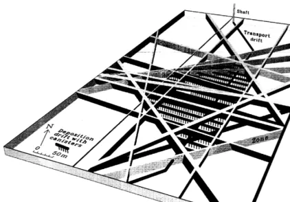
steel-coated copper canisters deposited in verti-cal holes about 1.5 m in diameter. A final full-scale repository might contain as many as 4500 canisters and thereby covering an area of about 1 km2. Fig. 1 shows a hypothetical
reposi-Ž .
tory about 10% of full-size placed at 500 m
¨
depth below the island Aspo. The three-dimen-
¨
Ž .
sional 3D fracture zone model in the figure, which governs the layout of the facility, was developed from surface-based investigations of
¨
Ž .the Aspo Tiren et al., 1996 . A fracture has to
¨
´
fulfil certain requirements to be included in the model, such as being possible to extrapolate and identify in more than one location, borehole or at the surface. The extrapolation of features was essentially performed with the directional bore-hole radar.3. Extrapolation of geological data
According to the definition, fractures are dis-continuities with mechanical or tectonic origin. In geology, the term is used to describe every-thing from microfractures to large faults. Fur-ther, the fractures can have several different chemical and physical properties: thus, the geo-physicist who wants to detect and classify frac-tures using borehole geophysics stands before a very challenging task. One reason is that no geophysical method reacts directly to the frac-ture. Instead, the geophysicist has to determine how each fracture affects the measurements recorded with the different probes. To simplify investigations concerning fractures, it is often assumed that the strike of the fracture is orthog-onal to the drillhole and filled with some fluid, usually water. Furthermore, the fracture surfaces are assumed to be smooth and perfectly plane.
struc-¨ Ž
Fig. 1. Layout of a potential repository located at 500 m depth governed by 3D structural model of Aspo, Sweden Tiren et¨ ´
.
al., 1996 . Fractures have to fulfill certain requirements to be included in the model, such as being possible to extrapolate and identify in more than one location, borehole or at the surface. The extrapolation of features was essentially performed with the directional borehole radar.
tural information along the hole going down-wards is usually not very difficult near the surface but becomes increasingly complicated
Ž as holes become deeper. At great depths c. 500
.
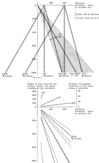
m , it is extremely difficult to determine which one of all the zones along the hole is the one that correlates with the surface expression, Fig. 2. The strike of a structure is generally well defined, based on the surface data, but the dip
Ž of the interpreted structure is at best based
.
solely on surface data determined with an accu-racy of"108.
Assume that there is a zone with an inter-preted dip of 60"108 westwards and that the mean spacing between fractured sections is con-stant. The number of equally possible
interpreta-tions is a function of the orientation of the borehole and the distance between the borehole and the structure at the surface, Fig. 2, where the average distance between minor zones is assumed to be 15 m, while it is 30 m between major zones. When a borehole dipping 608 to-wards the structure is drilled 50 m away from the structure there are two possible solutions in the most favorable case. The borehole will in-tersect the zone at 40 m depth. If, however, this example is repeated for the same zone at 500 m
Ž .
depth, there are several )10 equally possible solutions within a borehole length interval from
Ž
470 to 708 m corresponding to vertical depths .
Fig. 2. Potential error in the location of a zone at depth due to errors in borehole deviation measurements and dip
Ž .
rock, there will be several possible interpreta-tion of the locainterpreta-tion of a structure at great depths.
4. Borehole radar
Ž .
Ground penetrating radar GPR is a term that covers a group of high-frequency
electro-Ž .
magnetic methods EM . All these methods in-volve transmitting very high frequency EM waves and recording the resulting signals from reflections within the medium or from transmis-sion passing through the media. The technique can be used to examine and locate interfaces in solid or liquid media, which exhibit changes in electrical properties. The exact technique em-ployed, transmission or reflection, being deter-mined on the basis of the object exadeter-mined and the medium involved.
The borehole radar is a special case of con-ventional GPR with several features that distin-guish it from the surface tools. The most
impor-tant is perhaps that the borehole itself enables emplacement of the antennas quite close to the objects to be investigated, resulting in precise target responses. Furthermore, the receiver and transmitter antennas may be lowered into differ-ent holes, so called cross-hole measuremdiffer-ents. The information obtained with this setup often complements the single-hole reflection surveys. Two different properties of radar wave propaga-tion normally determined are velocity and atten-uation.
The propagation of electromagnetic waves through rocks and soils is mainly a function of the dielectric constant and the electrical conduc-tivity. The potential of a feature in the bedrock to show as a distinct radar reflector or anomaly depends primarily on the contrast in the dielec-tric constants of the feature and that of the
Ž .
bedrock Olsson et al., 1990 . Because of the large contrast in dielectric constant between
Ž .
bedrock about 5 and the water-filled pores Ždielectric constant for water is 81 in the frac-. tured rock the fractures are well indicated.
Ž .
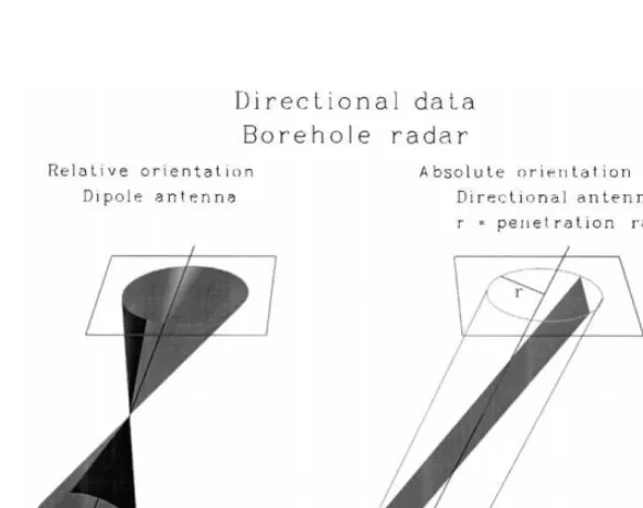
Fig. 3. Principle of results from two types of borehole radar antennas, conventional dipole left and directional antenna
4.1. Directional single-hole surÕeys
Most borehole antennas are axially oriented dipoles. Consequently, the response of a survey includes information from the entire volume of rock surrounding the hole. In our case, it is necessary to determine the orientation of single features and we have therefore used a direc-tional receiver antenna. It is direcdirec-tional in the sense that it allows for the absolute determina-tion of strike and dip of all planar reflectors. In Fig. 3, the principle of the interpreted results
from an omnidirectional dipole antenna is com-pared to that of the directional antenna.
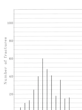
The design of the antenna limits the practical range of angles at which reflectors are deter-mined with the borehole radar. Fig. 4 shows an example of how the spatial density of fractures interpreted depends upon the angle of intersec-tion between the borehole and the fractures. There is no reason to assume that there is a bias in the natural distribution of zones in this rock mass and therefore this distribution can be as-sumed in other rocks as well.
Fig. 4. Distribution of fractures detected by borehole radar relative to the angle of intersection between borehole and
Ž .
Previous investigations show that the ability of the borehole radar to detect features within the rock mass appears to have a maximum when intersecting structures at an angle of c. 308, while it diminishes rapidly for lower tion angles and more slowly for higher
intersec-Ž .
tion angles. At high intersection angles -758 , the ability to detect structures is the lowest. This geometrical relationship has to be considered when planning borehole radar surveys and espe-cially when the target will be investigated from several holes drilled in different directions. The target could be a specific object such as a fracture zone, but it could also be a rock vol-ume. An orthogonal borehole configuration does not optimize the potential of the borehole radar, as there will be orientations of structures poorly
Ž .
sampled by all boreholes Tiren, 1998 .
´
Since the reflection coefficient is highly de-pendent on the variation in water-content in the rock mass the radar reflection surveys result in selective picking of features. Bedrock features that give rise to reflectors need to be of a certain
size and preferably, but not always, are the effect of water-saturated porosity.
The radar reflectors of concern in this study Ž are generally planar and large in extent 20–40
.
m or more structures. At the intersection of radar reflectors and borehole, the core logs of-ten express increased fracturing. Locally the fractures appear to be sealed.
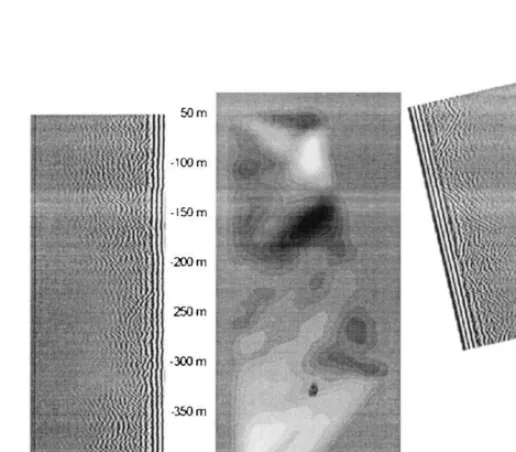
4.2. Tomography
The principle of cross-hole surveys is that the transmitter and receiver are located in such a manner that direct rays traveling between them pass through the medium. For each possible antenna configuration, a trace is recorded at the receiver. Each trace corresponds to a raypath between the boreholes. Along each raypath, the travel time and the amplitude of the first arriv-ing direct wave is determined. Both arrival times and amplitudes can be analyzed with tomo-graphic inversion.
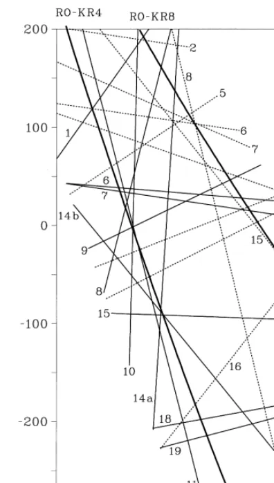
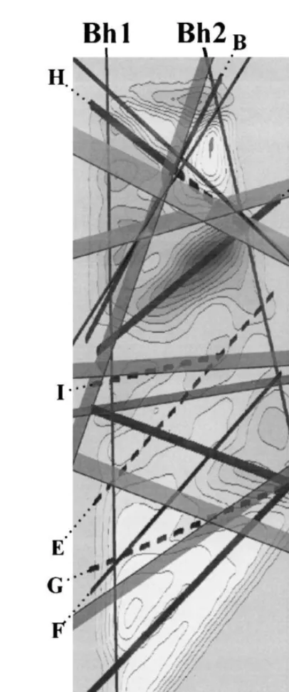
Fig. 6. Interpreted reflectors from directional antenna sur-veys in the two boreholes, plotted in the tomographic plane. Numbers to the left in plot are reflectors found in
Ž . Ž .
the left borehole RO-KR4 Carlsten and Wanstedt, 1996 .¨
Tomographic inversion involves dividing the interval between the boreholes into segments and assigning approximate values of the dielec-tric constant or attenuation to each segment in an iterative manner. The values are adjusted by means of the amplitudes and travel times of the rays passing through each segment, calculations are continued until the travel times and attenua-tions correspond to the measured values. The resolution of the method is a complex function of the wavelength, the transmitter and receiver
Ž .
point spacing along the respective holes , as well as the distance between the boreholes. The resolution is on the order of meters.
Tomography and reflection surveys are af-fected a bit differently by variations in the rock mass. For example, a wide, severely fractured and water-bearing zone will probably cause a reflection at either of the boundaries. The mini-mum velocity in the tomogram, on the other hand, will probably be located in the center of
Ž
the zone where the porosity and water content .
reaches a maximum .
4.3. Description of measurement setup
Borehole radar measurements were per-formed in two co-planar holes 509 and 301 m deep, respectively, at the Romuvaara investiga-tion site in Finland. Single-hole direcinvestiga-tional sur-veys were performed in each hole. Furthermore,
Fig. 7. Interpreted reflectors from directional antenna
sur-Ž .
cross-hole measurements were performed be-tween the holes. The distance bebe-tween the holes is 73 m at the surface and about 201 m at depth.
The use of a directional tool enables the determination of location, strike and dip of re-flectors in the vicinity of the hole. The
ter antenna, emitting 60-MHz radar waves, manages to survey a rock volume rock with a
Ž .
radius of 30 to 40 m in reflection mode Fig. 5 . This means that near the surface, it would be possible to record the same reflection from ei-ther of the holes if ei-there was an adequately oriented anomaly in the rock volume between the holes. At the bottom of the investigated plane the distance is much too far for the reflec-tion mode investigareflec-tion. As a result, it is not always easy to correlate zones between the two holes. It is even more difficult to extrapolate a zone accurately when the target is at the sur-face.
Radar waves for the cross-hole survey were generated with 22-MHz dipole antennas to cover the somewhat large distance in the deeper parts
Ž .
of the investigated plane Fig. 5 . In total, 4040 rays were recorded with a minimum length of 76.5 m and a maximum length of 222.0 m. Data quality of recorded rays was excellent and very
Ž
few rays had to be omitted 1.9% of the velocity .
rays and 2.1% of the amplitude rays .
5. Discussion of results
When plotted in the plane confined by the two holes, as in Fig. 6, it is difficult to extrapo-late and connect reflectors between the holes since there is no dip information.
If the interpreted reflectors are plotted in 3D ŽFig. 7 , there is a possibility to connect the. various features. Due to the quite large number of reflectors, this is still difficult. The distance is not, unfortunately, the only problem as there is a limited accuracy in the determination.
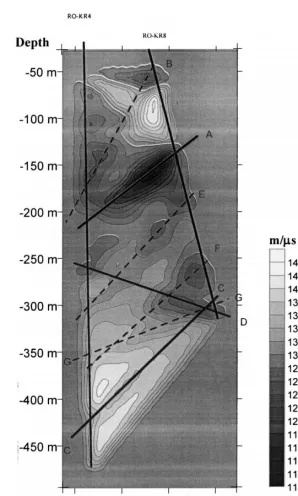
The tomographic inversion of the data re-sulted in plots of the velocity and amplitude distributions in the plane. In the plots, low velocity or high attenuation characterizes frac-ture zones across the plane. The feafrac-tures are generally easier to locate in the velocity
tomo-Ž .
gram Fig. 8 .
Six features were interpreted as significant zones and subsequently compared to the zones
found with the directional antenna. There are possibly more structures within the tomogram,
Fig. 9. Comparison of features interpreted from the veloc-ity tomogram and interpreted reflectors that show how overall structural interpretation can be improved. Labeled
Ž .
but they do not appear as clearly. The signifi-cant zones delineated by the velocity variations generally correlate with interpreted reflectors, although only a subset of the reflections
origi-Ž .
nate from the low velocity zones Fig. 9 . The low velocity zone in the tomogram around 200
Ž .
m Figs. 5 and 8 , appears to cause several reflections in both boreholes but the directions are contradictory. In fact, there are no reflectors that accurately describe the low velocity zone. With the information from the tomogram, the correct location of the zone can be established. Note that although the boreholes are quite close near the surface, there are not many interpreted reflectors that are found in both holes.
There are a few possible reasons for the discrepancy between single-hole surveys and cross-hole surveys. The most important reason in this case is probably the difference in resolu-tion.
6. Conclusions
A single-hole radar investigation is clearly a very helpful tool for understanding the struc-tural geology in the rock mass surrounding a borehole. Although the information is oriented, it is difficult to extrapolate reflectors between holes and to the surface.
When planning an investigation, it is neces-sary to be aware of the actual performance of the directional borehole radar. Since the tools does not cover all angles in the same way, the orientation of the holes should be planned tak-ing this into account.
Radar tomography treats the structures be-tween the holes a bit more stringently in that there is really no room for error in the dip
determination within the plane. Due to the high resolution, zones can be traced across the entire plane between the holes, or up to the surface.
Acknowledgements
Thanks are due to POSIVA OY for allowing us to publish the results of this investigation.
References
Carlsten, S., Wanstedt, S., 1996. Detailed borehole radar¨ measurements at the Romuvaara site, Finland. POSIVA OY Site Investigation Project Work Report PATU-96-52e, 64 pp.
Olsson, O., Falk, L., Forslund, O., Lundmark, L., Sand-berg, E., 1990. Crosshole investigations — results from borehole radar investigations. Stripa Project Technical Report 87-11, an OECDrNEA international projected managed by the Swedish Nuclear Fuel and Waste
Ž . Ž
Management SKB , Stockholm, 160 pp. revised Feb.
.
1990 .
SKB, 1992. SKB-91. Final disposal of spent nuclear fuel — importance of the bedrock for safety. SKB Techni-cal Report TR 92-20, Swedish Nuclear Fuel and Waste
Ž .
Management SKB , Stockholm, 197 pp.
Tiren, S.A., 1998. On the use of borehole radar measure-´ ments for 3D assessment of structures in rock volumes.
¨
In: Proceedings of the 3rd Aspo International Seminar¨ ‘‘Characterization and Evaluation of Sites for Deep Geological Disposal of Radioactive Waste in Fractured Rock’’, Oskarshamn, Sweden, June 10–12, 1998. SKB Technical Report TR 98-10, Swedish Nuclear Fuel and
Ž .
Waste Management SKB , Stockholm, pp. 99–107. Tiren, S.A., Beckholmen, M., Voss, C., Askling, P., 1996.´
SITE-94: Development of a Geological and a Structural ¨
Model of Aspo. SKI Report 96:16, Swedish Nuclear¨
Ž .
Power Inspectorate SKI , Stockholm, 198 pp. West, G., Carter, P.G., Dumbleton, M.J., Lakes, L.M.,