Flow Measurement
Diposting oleh Poppy di 4:29 PM
Pada kontrol proses, pendeteksian akurat terhadap flow rate dan mass flow gas, cairan dan zat padat memegang peranan yang sangat penting. Jenis fluida dan karakteristiknya merupakan faktor utama yang menentukan metode pengukuran yang paling sesuai dengan tujuan pengukuran.
Secara umum, Flow Meter dapat dibagi menjadi 2 jenis yaitu mekanik dan elektrik. Pada divais mekanik, metode yang paling umum untuk pengukuran flow adalah menempatkan sebuah halangan dalam aliran fluida pada pipa sehingga menghasilkan efek sekunder seperti torsi atau menempatkan sebuah lempeng yg terdapat lubang ditengahnya sehingga timbul perbedaan tekanan. Pada divais elektrik, beda potensial dibangkitkan oleh koil dengan fluida bergerak dalam medan magnet, frekuensi putaran turbin, perubahan kecepatan pada fluida bergerak , dan perubahan resistansi dari elemen yang terletak pada fluid path
Klasifikasi FLOW METER
Flow meter diklasifikasikan menjadi dua hal mendasar : (1) quantity dan (2) rate of flow. Quantity meter berhubungan dengan bobot atau volume fluida yang melewati primary element. Contohnya adalah positive-displacement meters (p/d meters), reciprocating piston, nutating discs , dll. Sedangkan untuk fluida yang melewati primary element pada arus kontinyu diketahui sebagai rate of flow meter . Contohnya adalah orifice plate, turbine dan electromagnetic flow meter.
1.Differential Pressure measurements : (a)Orifice plate, (b)venturi tube, (c)flow nozzle dan (d) pitot tube
2.Electromagnetic-flowmeters 3.Rotameter (variable-area meters)
4.Mechanical-Flow meters : positive displacement & turbine 5.Ultrasonic-flow meter
6.Vortex-flow meter
Differential Pressure Measurements
Dasar pengukuran menggunakan Teorema Bernoulli yaitu : “
jumlah energi pada suatu titik di dalam suatu aliran tertutup sama besarnya dengan jumlah energi di titik lain pada jalur aliran yg sama
“
Dimana :
p1 = tekanan per unit area pada FH v1 = kecepatan fluida pada BD v2 = kecepatan fluida pada FH
r = massa jenis fluida g = percepatan gravitasi
h1 = tinggi pusat gravitasi terhadap volume BCED h2 = tinggi pusat gravitasi terhadap volume FGIH
(a)Orifice Plate merupakan lempeng berlubang yang digunakan untuk mengukur tingkat aliran dalam sistem pipa. Dengan Orifice Plate yang disisipkan pada pipa , dapat ditimbulkan pressure drop. Berdasarkan besar pressure drop,laju aliran (flow rate) dapat dihitung. Alat ini sangat praktis untuk tabung berdiameter besar dan fluida yang kotor. Salah satu contoh bentuk orifice plate dapat dilihat pada gambar di awal tulisan ini. (to be continued)
Referensi :
1. Liptak, Bela G, 2003, Instrument Engineers Handbook.Process measurement and analysis, CRC PRESS, ISA, USA
2.Rangan C.S, Sarma G.R and Mani V.S.V, 1992, Instrumentation : Devices and Systems, Tata McGraw-Hill, New Delhi
Flow Measurement
Introduction
Flow measurement applications in the water industry range from small dosing and treatment flows in pipes of a few millimeters in diameter, to the flow of treated or wastewater in trunk mains and aqueducts of 2m diameter and above. Often in the larger cities, large interceptor sewers are used to collect vast volumes of effluent and spent water, to convey them to waste water treatment plant for processing. Some interceptors are several meters in diameter, maybe of special shape and usually running partially full. Flow meter usage is therefore wide and diverse and is at the center of the entire water cycle within the industry. Metering influences resource management, process control, new works planning, distribution management, leakage detection, financial control and environmental issues either directly or indirectly.
Managing Water Distribution Systems
Water imbalances are becoming a key focus to increase the reliability and quality of supply. The complete supply system consists of a number of elements. Each needs to be effectively managed and controlled if the overall supply cycle is to remain within tight control. A typical system, shown in figure 1, usually consists of the following main elements:
Raw water piping system between abstraction and primary treatment plant Piping and components within the water treatment works
Transmissions mains and supply storage reservoirs Local distribution supply mains
Connection pipes to the consumers premises
Piping in the consumers premises after the point of final metering
Water is drawn from the source, through an abstraction meter (SP1) and into the treatment plant. A second supply meter (SP2) may identify losses in the supply main. From the treatment plant, water passes through the outlet meters (OMs) into the transmission mains and finally into local reservoirs. District meters measure the amount taken out from these reservoirs into each district and finally area meters (AMs) measure flow in smaller supply mains into each sub-division, when the supply mains split after the DMAs. Further down each area, there may be individual meters for shops, apartment complexes and factories. It is vital that all the meters within this system are of known performance and regularly maintained, so the water balance within any section can be documented and the uncertainty correctly estimated, as losses or imbalances can (and do) occur in any or all of the above.
In the first area, large volumes of water are involved through a few key flow meters. Consider a large Venturi meter for example in a 1600mm pipe measuring a flow of 250MLD. Over a period of time the inside surface of the pipes and parts of the meter will change (due to deposits) and general experience shows the meter may begin to under-read. The intrinsic ‘accuracy’ is fundamental to managing the water balance. If the same type of meter were used through the supply system, then all could drift in the same way and at almost the same rate. We could have the situation were the meters may balance, but the quantitative assessment of the flow is in error. This has been the case in a good proportion of the older networks. Invariably these meters have not been properly installed, calibrated or maintained, but are still used to measure the amount of water put into supply. Knowledge and experience of installing flow meters, it may be argued that this total is never precisely known.
Flow metering techniques within the water industry
In water supply systems, the common methods used almost always come from differential pressure types, displacement types, inferential types, magnetic types, ultrasonic types, and open channel types. By far the largest numbers sold are the domestic inferential meters for individual usage in houses, apartments, factories, etc. Millions are used worldwide and have formed the backbone of network supply management for the past three decades. Bulk supply has traditionally been monitored with Venturi or Dall tubes or large propeller meters, but recently magnetic meters are increasingly used for such applications. From the very many types that are described, it is possible to compose a basic application table, largely based on experience and tradition. It should not be considered as the final means of selecting the best meter, but merely to give an indication of the choice.
For the elements shown in figure 1, the current practice is to use ultrasonic or magnetic meters wherever possible, governed of course by costs. As large meter costs can vary enormously, the balance has to be struck between spending the right amount of money for an economic return. Normally meters are chosen purely on cost grounds, but experience throughout the world shows
this may not necessarily be the optimum. Life cycle costs are a much better means of judging instrument selection.
Expected and actual installed meter performance
When purchasing any instrument, the supplier usually gives a written specification for that device. Some manufacturers give detailed performances backed by independent testing while a minority of specifications barely enables the prospective user to determine what they are purchasing. Flow meters are a little different to other instruments. They are tested in a flow laboratory under reference conditions. This means that standard flow rates are used in long straight pipes under steady flow conditions. Few manufacturers have comprehensive data on installation effects and often are reluctant to part with this data. An installation effect is defined as the variation from laboratory calibration to that obtained under field conditions.
Examples of flow meter installation effects are:
Differences in pipe characteristics (roughness, ovality, etc.)
Proximity of fittings (valves/bends) which are not present in reference testing Differences in temperature (fluid and ambient)
Effect of local RFI which are not present in reference testing Signal acquisition and processing errors of the local system
The laboratory data are relevant for the meter in the laboratory set-up only. Once the meter is installed in the customer’s pipe, other changes may be introduced and may include:
Bore of the mating pipe is usually different to that of the meter
The flow rates in the transmission lines may be different to the lab data There may be sediment, or calcification effects within the network
All these variables may introduce additional bias into the meter readings from the day a meter is installed. This can only be estimated or quantified from verification and this should form part of regular network management activities. Many users, when purchasing flow meters, expect the manufacturer’s specification to apply immediately and be stable with time. This is a popular misconception. For example, small mechanical meters are always tested at the manufacturer’s premises in accordance with local Weights and Measures regulations or international metrology standards. This is the guarantee to the user that when it leaves the factory it is within predetermined calibration limits. If it is incorrectly installed, installed too close to valves or used on water supply with high sediment content, its performance may shift from the as-new calibration. Usually, though not always, it under-records and over a period due to component wear, this under-registration may increase. There may be a steady but noticeable fall in accuracy of the meter with time. This trend is not just for these types of meters. ALL flow meters, whatever the type from any source of supply, show these time dependent effects to varying degrees. The key to successful network management is to estimate the rate of degradation (if present) with time.
It is actually quite difficult to calibrate flow meters to much better than 0.2% total uncertainty, so this represents the baseline when any meter leaves a manufacturing facility. When the user installs the meter, this 0.2% lab figure almost certainly changes (increases). The outlet meters from a water treatment plant for example should have the highest accuracy and the best installation practice. This is because they are handling large volumes of treated water being put into supply. Any flow meters of 250mm and above should be carefully selected and even more carefully installed. Poor installation causes the greatest source of error. Standards give guidance on the effect of single fittings but little data exists on the effect of multiple fittings close to flow meters. The main problem is that even accepted standards currently in use may not be totally correct, usually being out of date due to the rapid developments currently taking place in metering. This is why site verification is vital to ensure the meter readings are valid.
All flow meters are affected by lack of attention at the installation stage to details such as protruding gaskets, pipe bore alignment, the proximity of valves, presence of pipe branches etc. In addition to these hydraulic considerations, close attention must be given to environmental aspects on secondary equipment to avoid excessive vibration, flooding, ambient temperature swings and other effects. These can greatly affect the actual measurement uncertainty that can be achieved.
The overall recommendation, taking account of the many installation factors listed above, is that it is often difficult to demonstrate total installed errors of much better than 2% anyway. It is suggested that in order to achieve this long-term figure, it is necessary to specify instruments with an intrinsic uncertainty of around 0.25% or better and this then allows more than 1.75% for
all the additional unquantified effects. More attention should be paid to the nature of the meter chosen and the application needs. If water companies would standardize on this 2% value, it is suggested that leakage figures would become much more understandable. It is essential that all meters are site verified to ensure that this 2% value is maintained, (or at the least any deviation is estimated).
Modern Installation practices and the cost implications of metering
Cost often dictates the choice of meter and the design of the complete installation, but unfortunately it is usually only the purchase price of the equipment that is the driving factor. The full cost of flow measurement is not simply buying the instrument. Recent independent studies have shown this is only around 40% of the total cost of owning and operating the meter in the first year. The actual price depends heavily on the meter specification such as pressure ratings, materials of constructions, transmitter functionality etc. Installing the meter is actually the single most expensive item in the first year. This covers both mechanical and electrical installation as well as the purchase of piping and ancillaries. As a result many water supply Authorities around the world have focused on reducing installations costs. Previously meters had been installed in chambers to allow access for maintenance and calibration. Modern flow meters however require little maintenance and recent advances in electronic signal processing and fault diagnostics have allowed field devices to be developed that do not require direct access to the meter. These use electronic fingerprinting to look for changes in both meter and transmitter characteristics.
It is clear that accurate metering is fundamental to the future conservation of water resources and to the successful financial and operational management of existing water supply networks. Without metering, the true loss of water cannot be assessed and this can in turn lead to financial under-recovery and possible errors in capital investment within the industry. An economic reduction in leakage rates can render the investment in new water sources, dams, treatment works or reservoirs unnecessary, or at the least enable a better economic justification to be made. Studies have shown that in major city water supply networks, financial uncertainties in excess of several millions of US dollars per day are easily possible. When set against the cost of good instrumentation and maintenance practices, such leakage costs are very significant. This is why so many cities around the world are investing in long term projects for water loss reduction.
In the near future, as digital electronics and communications protocols become more accepted, flow meters are expected to evolve into small metering systems (pressure, flow temperature and alarm capability at each point). Indeed even the small domestic mechanical meters are undergoing radical development and evaluation. They are evolving into solid-state devices, linked to telephone systems, satellite dishes, local cable TV or other lines into properties, so that flow rate, consumption and other data can be automatically transmitted back to central centers for collation and billing.
FLOWMETER TYPES AND THEIR PRINCIPLES
INTRODUCTION
Measuring the flow of liquids is a critical need in many industrial plants. In some operations, the ability to conduct accurate flow measurements is so important that it can make the difference between making a profit or taking a loss. In other cases, inaccurate flow measurements or failure to take measurements can cause serious (or even disastrous) results.
With most liquid flow measurement instruments, the flow rate is determined inferentially by measuring the liquid's velocity or the change in kinetic energy. Velocity depends on the pressure differential that is forcing the liquid through a pipe or conduit. Because the pipe's cross-sectional area is known and remains constant, the average velocity is an indication of the flow rate. The basic relationship for determining the liquid's flow rate in such cases is:
Q = V x A where
Q = liquid flow through the pipe V = average velocity of the flow A = cross-sectional area of the pipe
Other factors that affect liquid flow rate include the liquid's viscosity and density, and the friction of the liquid in contact with the pipe.
Direct measurements of liquid flows can be made with positive-displacement flowmeters. These units divide the liquid into specific increments and move it on. The total flow is an accumulation of the measured increments, which can be counted by mechanical or electronic techniques.
Reynolds Numbers
The performance of flowmeters is also influenced by a dimensionless unit called the Reynolds Number. It is defined as the ratio of the liquid's inertial forces to its drag forces.
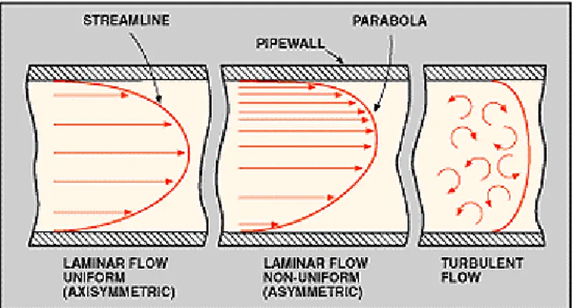
Figure 1: Laminar and turbulent flow are two types normally encountered in
liquid flow Measurement operations. Most applications involve turbulent flow, with R values above 3000. Viscous liquids usually exhibit laminar flow, with R values below 2000. The transition zone between the two levels may be either laminar or turbulent.
The equation is: R = 3160 x Q x Gt
D x h where:
R = Reynolds number Q = liquid's flow rate, gpm Gt = liquid's specific gravity D = inside pipe diameter, in. h = liquid's viscosity, cp
The flow rate and the specific gravity are inertia forces, and the pipe diameter and viscosity are drag forces. The pipe diameter and the specific gravity remain constant for most liquid
layers with the highest velocity at the center of the pipe and low velocities at the pipe wall where the viscous forces restrain it. This type of flow is called laminar flow. R values are below
approximately 2000. A characteristic of laminar flow is the parabolic shape of its velocity profile, Fig. 1.
However, most applications involve turbulent flow, with R values above 3000. Turbulent flow occurs at high velocities or low viscosities. The flow breaks up into turbulent eddies that flow through the pipe with the same average velocity. Fluid velocity is less significant, and the velocity profile is much more uniform in shape. A transition zone exists between turbulent and laminar flows. Depending on the piping configuration and other installation conditions, the flow may be either turbulent or laminar in this zone.
FLOWMETER TYPES
Differential Pressure Positive Displacement Velocity Mass Open-Channel
Orifice Plate Venturi Tube Flow Tube Flow Nozzle Pitot Tube Elbow Tap Target Variable-Area(Rotameter) Reciprocating Piston Oval Gear Nutating Disk Rotary Vane Turbine Vortex Shedding Swirl
Conada Effect & Momentum Exchange Electromagnetic Ultrasonic, Doppler Ultrasonic, Transit-Time Coriolis Thermal Weir Flume
Numerous types of flowmeters are available for closed-piping systems. In general, the equipment can be classified as differential pressure, positive displacement, velocity, and mass meters.
Differential pressure devices (also known as head meters) include orifices, venturi tubes, flow tubes, flow nozzles, pitot tubes, elbow-tap meters, target meters, and variable-area meters, Fig. 2.
Positive displacement meters include piston, oval-gear, nutating-disk, and rotary-vane types. Velocity meters consist of turbine, vortex shedding, electromagnetic, and sonic designs. Mass meters include Coriolis and thermal types. The measurement of liquid flows in open channels generally involves weirs and flumes.
Differential Pressure Meters
The use of differential pressure as an inferred measurement of a liquid's rate of flow is well known. Differential pressure
flowmeters are, by far, the most common units in use today. Estimates are that over 50 percent of all liquid flow measurement applications use this type of unit.
The basic operating principle of differential pressure flowmeters is based on the premise that the pressure drop across the meter is proportional to the square of the flow rate. The flow rate is obtained by measuring the pressure differential and extracting the square root.
Differential pressure flowmeters, like most flowmeters, have a primary and secondary element. The primary element causes a change in kinetic energy, which creates the differential pressure in the pipe. The unit must be properly matched to the pipe size, flow conditions, and the liquid's properties. And, the measurement accuracy of the element must be good over a reasonable range. The secondary element measures the differential pressure and provides the signal or read-out that is converted to the actual flow value.
Orifices are the most popular liquid flowmeters in use today. An orifice is simply a flat piece of metal with a specific-sized hole bored in it. Most orifices are of the concentric type, but
eccentric, conical (quadrant), and segmental designs are also available.
In practice, the orifice plate is installed in the pipe between two flanges. Acting as the primary device, the orifice constricts the flow of liquid to produce a differential pressure across the plate. Pressure taps on either side of the plate are used to detect the difference. Major advantages of orifices are that they have no moving parts and their cost does not increase significantly with pipe size.
Conical and quadrant orifices are relatively new. The units were developed primarily to measure liquids with low Reynolds numbers. Essentially constant flow coefficients can be maintained at R values below 5000. Conical orifice plates have an upstream bevel, the depth and angle of which must be calculated and machined for each application.
The segmental wedge is a variation of the segmental orifice. It is a restriction orifice primarily designed to measure the flow of liquids containing solids. The unit has the ability to measure flows at low Reynolds numbers and still maintain the desired square-root relationship. Its design is simple, and there is only one critical dimension the wedge gap. Pressure drop through the unit is only about half that of conventional orifices.
Integral wedge assemblies combine the wedge element and pressure taps into a one-piece pipe coupling bolted to a conventional pressure transmitter. No special piping or fittings are needed to install the device in a pipeline.
Metering accuracy of all orifice flowmeters depends on the installation conditions, the orifice area ratio, and the physical properties of the liquid being measured.
Venturi tubes have the advantage of being able to handle large flow volumes at low pressure drops. A venturi tube is essentially a section of pipe with a tapered entrance and a straight throat. As liquid passes through the throat, its velocity increases, causing a pressure differential between the inlet and outlet regions.
The flowmeters have no moving parts. They can be installed in large diameter pipes using
flanged, welded or threaded-end fittings. Four or more pressure taps are usually installed with the unit to average the measured pressure. Venturi tubes can be used with most liquids, including those having a high solids content.
Flow tubes are somewhat similar to venturi tubes except that they do not have the entrance cone. They have a tapered throat, but the exit is elongated and smooth. The distance between the front face and the tip is approximately half the pipe diameter. Pressure taps are located about one-half pipe diameter downstream and one pipe diameter upstream.
Flow Nozzles, at high velocities, can handle approximately 60 percent greater liquid flow than orifice plates having the same pressure drop. Liquids with suspended solids can also be metered. However, use of the units is not recommended for highly viscous liquids or those containing large amounts of sticky solids.
Pitot tubes sense two pressures simultaneously, impact and static. The impact unit consists of a tube with one end bent at right angles toward the flow direction. The static tube's end is closed, but a small slot is located in the side of the unit. The tubes can be mounted separately in a pipe or combined in a single casing.
Pitot tubes are generally installed by welding a coupling on a pipe and inserting the probe through the coupling. Use of most pitot tubes is limited to single point measurements. The units are susceptible to plugging by foreign material in the liquid. Advantages of pitot tubes are low cost, absence of moving parts, easy installation, and minimum pressure drop.
Elbow tap meters operate on the principle that when liquid travels in a circular path, centrifugal force is exerted along the outer edges. Thus, when liquid flows through a pipe elbow, the force on the elbow's interior surface is proportional to the density of the liquid times the square of its velocity. In addition, the force is inversely proportional to the elbow's radius.
Any 90 deg. pipe elbow can serve as a liquid flowmeter. All that is required is the placement of two small holes in the elbow's midpoint (45 deg. point) for piezometer taps. Pressure-sensing lines can be attached to the taps by using any convenient method. The difference in pressure on the outside and inside walls, caused by centrifugal force, can be measured with a differential pressure transducer. Figure 2 shows a typical installation.
Pressure measurements are obtained by placing taps at 45- degree angles on opposite sides of the elbow. The size of each of the two taps should not exceed one-eighth of the pipe diameter. Flow is calculated according to the following formula:
where W = flow in pounds per hour r = elbow radius (inches)
D = elbow diameter (inches)
h = differential pressure (inches H20)
p = density in lbs/ft3
Target meters sense and measure forces caused by liquid impacting on a target or drag-disk suspended in the liquid stream. A direct indication of the liquid flow rate is achieved by measuring the force exerted on the target. In its simplest form, the meter consists only of a hinged, swinging plate that moves outward, along with the liquid stream. In such cases, the device serves as a flow indicator.
A more sophisticated version uses a precision, low-level force transducer sensing element. The force of the target caused by the liquid flow is sensed by a strain gage. The output signal from the gage is indicative of the flow rate. Target meters are useful for measuring flows of dirty or
corrosive liquids.
Variable-area meters, often called rotameters, consist essentially of a tapered tube and a float, Fig. 3. Although classified as differential pressure units, they are, in reality, constant differential pressure devices. Flanged-end fittings provide an easy means for installing them in pipes. When there is no liquid flow, the float rests freely at the bottom of the tube. As liquid enters the bottom of the tube, the float begins to rise. The float is selected so as to have a density higher than that of the fluid and the position of the float varies directly with the flow rate. Its exact position is at the point where the differential pressure between the upper and lower surfaces balance the weight of the float.
Because the flow rate can be read directly on a scale mounted next to the tube, no secondary flow-reading devices are necessary. However, if desired, automatic sensing devices
can be used to sense the float's level and transmit a flow signal. Rotameter tubes are
manufactured from glass, metal, or plastic. Tube diameters vary from 1/4 to greater than 6 in. Positive-Displacement Meters
Operation of these units consists of separating liquids into accurately measured increments and moving them on. Each segment is counted by a connecting register. Because every increment represents a discrete volume, positive-displacement units are popular for automatic batching and accounting applications. Positive-displacement meters are good candidates for measuring the flows of viscous liquids or for use where a simple mechanical meter system is needed.
Reciprocating piston meters are of the single and multiple-piston types. The specific choice depends on the range of flow rates required in the particular application. Piston meters can be used to handle a wide variety of liquids. A magnetically driven, oscillating piston meter is shown in Fig. 4. Liquid never comes in contact with gears or other parts that might clog or corrode.
Oval-gear meters have two rotating, oval-shaped gears with synchronized, close fitting teeth. A fixed quantity of liquid passes through the meter for each revolution. Shaft rotation can be monitored to obtain specific flow rates.
Nutating-disk meters have a moveable disk mounted on a concentric sphere located in a spherical side-walled chamber. The pressure of the liquid passing through the measuring
chamber causes the disk to rock in a circulating path without rotating about its own axis. It is the only moving part in the measuring chamber.
A pin extending perpendicularly from the disk is connected to a mechanical counter that
monitors the disk's rocking motions. Each cycle is proportional to a specific quantity of flow. As is true with all positive-displacement meters, viscosity variations below a given threshold will affect measuring accuracies. Many sizes and capacities are available. The units can be made from a wide selection of construction materials.
Rotary-vane meters are available in several designs, but they all operate on the same principle. The basic unit consists of an equally divided, rotating impeller (containing two or more
compartments) mounted inside the meter's housing. The impeller is in continuous contact with the casing. A fixed volume of liquid is swept to the meter's outlet from each compartment as the impeller rotates. The revolutions of the impeller are counted and registered in volumetric units. Helix flowmeters consist of two radically pitched helical rotors geared together, with a small clearance between the rotors and the casing. The two rotors displace liquid axially from one end of the chamber to the other.
Velocity Meters
These instruments operate linearly with respect to the volume flow rate. Because there is no square-root relationship (as with differential pressure devices), their rangeability is greater. Velocity meters have minimum sensitivity to viscosity changes when used at Reynolds numbers above 10,000. Most velocity-type meter housings are equipped with flanges or fittings to permit them to be connected directly into pipelines.
Turbine meters have found widespread use for accurate liquid measurement applications. The unit consists of a multiple-bladed rotor mounted with a pipe, perpendicular to the liquid flow. The rotor spins as the liquid passes through the blades. The rotational speed is a direct function of flow rate and can be sensed by magnetic pick-up, photoelectric cell, or gears. Electrical pulses can be counted and totalized, Fig. 5.
The number of electrical pulses counted for a given period of time is directly proportional to flow volume. A tachometer can be added to measure the turbine's rotational speed and to
determine the liquid flow rate. Turbine meters, when properly specified and installed, have good accuracy, particularly with low-viscosity liquids.
A major concern with turbine meters is bearing wear. A "bearingless" design has been developed to avoid this problem. Liquid entering the meter travels through the spiraling vanes of a stator that imparts rotation to the liquid stream. The stream acts on a sphere, causing it to orbit in the space between the first stator and a similarly spiraled second stator. The orbiting movement of the sphere is detected electronically. The frequency of the resulting pulse output is proportional to flow rate.
Vortex meters make use of a natural phenomenon that occurs when a liquid flows around a bluff object. Eddies or vortices are shed alternately downstream of the object. The frequency of the vortex shedding is directly proportional to the velocity of the liquid flowing through the meter, Fig. 6.
The three major components of the flowmeter are a bluff body strut-mounted across the flowmeter bore, a sensor to detect the presence of the vortex and to generate an electrical impulse, and a signal amplification and conditioning transmitter whose output is proportional to the flow rate, Fig. 7. The meter is equally suitable for flow rate or flow totalization
Swirl Meter
The principle of operation of a swirl flowmeter is as follows. The meter body has a set of blades welded at the inlet, called the swirler. These blades impart a tangential velocity (or swirl) to liquids, gases or vapors. The fluid is then accelerated by a reduction in the meter body bore. A piezoelectric sensor is located in the center of the meter at the point of maximum fluid velocity. Flow is then decelerated as it approaches the meter outlet by an increase in meter body bore. A deswirler is welded to the meter body near the outlet. This deswirler eliminates the tangential velocity imparted to the fluid at the inlet so that other instrumentation downstream of the meter will not be affected by its operation.
A swirl flowmeter consists of the flowmeter body and an electronics housing (the electronics can be remote mounted for safety or convenience). Swirlmeters are only available with flanged meter bodies. A wafer option is not available, as there is for vortex meters. Swirlmeters use the same sensors and electronics as vortex meters, only the meter bodies differ in design.
Swirlmeters are most cost effective with stainless steel construction, although Hastelloy is also offered. Swirlmeters are available in sizes from 1 to 16 inches, and have options for ANSI 150, 300 or 600 mating flanges.
Conada Effect Flowmeter & Momentum Exchange Flowmeter.
While vortex shedding flowmeters are the most recognized types of oscillating flow measurement devices, less well known are meters based on the Coanda Effect, and the phenomenon known as momentum exchange.
The Coanda Effect is named after aerodynamicist Henri-Marie Coanda, who discovered that a free jet emerging from a nozzle or conduit will follow a nearby surface and attach to it. Fluid flowing through the meter body bends toward and attaches to a sidewall. A portion of the flow is diverted through a feedback passage, however, and pushes the stream toward a sidewall on the opposite side of the meter body, which also has a feedback passage through which a portion of the flow is diverted. The fluid from this feedback passage pushes the stream back toward the sidewall to which it was initially attached, and the self-initiating, self-sustaining process is repeated. A sensor, located in one of the two feedback passages, detects the presence and absence of flow. The frequency of the pulse signals is linear with volumetric flow rate. The momentum exchange flowmeter is similar to the Coanda model, but relies on a different mechanism to create oscillations. Unlike the Coanda meter, the momentum exchange meter does not have sidewalls. The shape of the meter body creates a main flow that passes through the nozzle and towards one side of the meter body or the other. This creates a flow pulse in a feedback passage, exerting a force on the main jet and deflecting it so it exerts a force on the fluid in the opposite passage. The pattern repeats continuously, creating a self-sustaining oscillation. Like the Coanda meter, it has a sensor in one of the feedback passages that detects the pulsing of fluids.
While most oscillating flowmeters -- including the Coanda fluidic flowmeter -- require turbulent flows to function, the momentum exchange meter does not, enabling its use with high-viscosity fluids.
Like other types of oscillating flowmeters, benefits include minimum maintenance, high stability and relatively inexpensive purchase cost. However, they are limited to use on pipes four inches in diameter or less. Use of larger pipes would create too few pulses per gallon for accurate measurement.
Electromagnetic meters can handle most liquids and slurries, providing that the material being metered is electrically conductive. Major components are the flow tube (primary element), Fig. 8. The flow tube mounts directly in the pipe. Pressure drop across the meter is the same as it is through an equivalent length of pipe because there are no moving parts or obstructions to the flow. The voltmeter can be attached directly to the flow tube or can be mounted remotely and connected to it by a shielded cable.
Electromagnetic flowmeters operate on Faraday's law of electromagnetic induction that states that a voltage will be induced when a conductor moves through a magnetic field. The liquid serves as the conductor; the magnetic field is created by energized coils outside the flow tube, Fig. 9. The amount of voltage produced is directly proportional to the flow rate. Two electrodes mounted in the pipe wall detect the voltage, which is measured by the secondary element. Electromagnetic flowmeters have major advantages: They can measure difficult and corrosive liquids and slurries; and they can measure forward as well as reverse flow with equal accuracy. Disadvantages of earlier designs were high power consumption, and the need to obtain a full pipe and no flow to initially set the meter to zero. Recent improvements have eliminated these
problems. Pulse-type excitation techniques have reduced power consumption, because excitation occurs only half the time in the unit. Zero settings are no longer required.
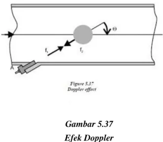
Ultrasonic flowmeters can be divided into Doppler meters and time-of-travel (or transit) meters.
Doppler meters measure the frequency shifts caused by liquid flow. Two transducers(one to transmit and the other to receive signal) are mounted in a case attached to one side of the pipe. A signal of known frequency is sent into the liquid to be measured. Solids, bubbles, or any
discontinuity in the liquid, cause the pulse to be reflected to the receiver element, Fig. 10. Because the liquid causing the reflection is moving, the frequency of the returned pulse is shifted. The frequency shift is proportional to the liquid's velocity.
A portable Doppler meter capable of being operated on AC power or from a rechargeable power pack has recently been developed. The sensing heads are simply clamped to the outside of the pipe, and the instrument is ready to be used. Total weight, including the case, is 22 lb. A set of 4 to 20 millampere output terminals permits the unit to be connected to a strip chart recorder or other remote device.
Because solids particles or entrained gases are required for measurement, Doppler meters are not appropriate for clean liquids. In general, Doppler flowmeters are less accurate than TOF
flowmeters, however, they are less expensive.
Time-of-travel(Transit-Time) meters have transducers mounted on each side of the pipe. The configuration is such that the sound waves traveling between the devices are at a 45 deg. angle to the direction of liquid flow. The speed of the signal traveling between the transducers increases or decreases with the direction of transmission and the velocity of the liquid being measured. A time-differential relationship proportional to the flow can be obtained by transmitting the signal alternately in both directions.
A limitation of time-of-travel meters is that the liquids being measured must be relatively free of entrained gas or solids to minimize signal scattering and absorption.
Mass Flowmeters
The continuing need for more accurate flow measurements in mass-related processes (chemical reactions, heat transfer, etc.) has resulted in the development of mass flowmeters. Various designs are available, but the one most commonly used for liquid flow applications is the
Coriolis meter. Its operation is based on the natural phenomenon called the Coriolis force, hence the name.
Coriolis meters are true mass meters that measure the mass rate of flow directly as opposed to volumetric flow. Because mass does not change, the meter is linear without having to be adjusted for variations in liquid properties. It also eliminates the need to compensate for changing
temperature and pressure conditions. The meter is especially useful for measuring liquids whose viscosity varies with velocity at given temperatures and pressures.
Coriolis meters are also available in various designs. A popular unit consists of a U-shaped flow tube enclosed in a sensor housing connected to an electronics unit. The sensing unit can be installed directly into any process. The electronics unit can be located up to 500 feet from the sensor.
Inside the sensor housing, the U-shaped flow tube is vibrated at its natural frequency by a magnetic device located at the bend of the tube. The vibration is similar to that of a tuning fork, covering less than 0.1 in. and completing a full cycle about 80 times/sec. As the liquid flows through the tube, it is forced to take on the vertical movement of the tube, Fig. 11. When the tube is moving upward during half of its cycle, the liquid flowing into the meter resists being forced up by pushing down on the tube.
Having been forced upward, the liquid flowing out of the meter resists having its vertical motion decreased by pushing up on the tube. This action causes the tube to twist. When the tube is moving downward during the second half of its vibration cycle, it twists in the opposite direction.
Having been forced upward, the liquid flowing out of the meter resists having its vertical motion decreased by pushing up on the tube. This action causes the tube to twist. When the tube is
moving downward during the second half of its vibration cycle, it twists in the opposite
direction. The amount of twist is directly proportional to the mass flow rate of the liquid flowing through the tube. Magnetic sensors located on each side of the flow tube measure the tube velocities, which change as the tube twists. The sensors feed this information to the electronics unit, where it is processed and converted to a voltage proportional to mass flow rate. The meter has a wide range of applications from adhesives and coatings to liquid nitrogen.
This meter has extremely high accuracy but can also cause a high pressure drop.
Thermal-type mass flowmeters have traditionally been used for gas measurements, but designs for liquid flow measurements are
available. These mass meters also operate independent of density, pressure, and viscosity. Thermal meters use a heated sensing element isolated from the fluid flow path. The flow stream conducts heat from the sensing element. The conducted heat is directly
proportional to the mass flow rate. The sensor never comes into direct contact with the liquid, Fig. 12. Through pre-existing built-in calibrations, the temperature differential is translated to mass flow. The accuracy of the thermal mass flow device is dependent on the reliability of the calibrations of the actual process gas or liquid and variations in the temperature, pressure, flow rate, heat capacity and viscosity of the fluid. The electronics package includes the flow analyzer, temperature compensator, and a signal conditioner that provides a linear output directly proportional to mass flow.
Open Channel Meters
The "open channel" refers to any conduit in which liquid flows with a free surface. Included are tunnels, nonpressurized sewers, partially filled pipes, canals, streams, and rivers. Of the many techniques available for monitoring open-channel flows, depth-related methods are the most common. These techniques presume that the instantaneous flow rate may be determined from a measurement of the water depth, or head. Weirs and flumes are the oldest and most widely used primary devices for measuring open-channel flows.
Weirs operate on the principle that an obstruction in a channel will cause water to back up, creating a high level (head) behind the barrier. The head is a function of flow velocity, and, therefore, the flow rate through the device. Weirs consist of vertical plates with sharp crests. The
top of the plate can be straight or notched. Weirs are classified in accordance with the shape of the notch. The basic types are V-notch, rectangular, and trapezoidal.
Flumes are generally used when head loss must be kept to a minimum, or if the flowing liquid contains large amounts of suspended solids. Flumes are to open channels what venturi tubes are to closed pipes. Popular flumes are the Parshall and Palmer-Bowlus designs.
The Parshall flume consists of a converging upstream section, a throat, and a diverging
downstream section. Flume walls are vertical and the floor of the throat is inclined downward. Head loss through Parshall flumes is lower than for other types of open-channel flow measuring devices. High flow velocities help make the flume self-cleaning. Flow can be measured
accurately under a wide range of conditions.
Palmer-Bowlus flumes have a trapezoidal throat of uniform cross section and a length about equal to the diameter of the pipe in which it is installed. It is comparable to a Parshall flume in accuracy and in ability to pass debris without cleaning. A principal advantage is the comparative ease with which it can be installed in existing circular conduits, because a rectangular approach section is not required.
Discharge through weirs and flumes are a function of level, so level measurement techniques must be used with the equipment to determine flow rates. Staff gages and float-operated units are the simplest devices used for this purpose. Various electronic sensing, totalizing, and recording systems are also available.
A more recent development consists of using ultrasonic pulses to measure liquid levels.
Measurements are made by sending sound pulses from a sensor to the surface of the liquid, and timing the echo return. Linearizing circuitry converts the height of the liquid into flow rate. A strip chart recorder logs the flow rate, and a digital totalizer registers the total gallons. Another recently introduced microprocessor-based system uses either ultrasonic or float sensors. A key-pad with an interactive liquid crystal display simplifies programming, control, and calibration tasks.
Flow measurement
From Wikipedia, the free encyclopedia
Flow measurement is the quantification of bulk fluid movement. Flow can be measured in a variety of ways. Positive-displacement flow meters accumulate a fixed volume of fluid and then count the number of times the volume is filled to measure flow. Other flow measurement
methods rely on forces produced by the flowing stream as it overcomes a known constriction, to indirectly calculate flow. Flow may be measured by measuring the velocity of fluid over a known area.
Contents
1 Units of measurement o 1.1 Gas
o 1.2 Liquid
2 Mechanical flow meters
o 2.1 Piston meter/Rotary piston o 2.2 Gear meter
2.2.1 Oval gear meter 2.2.2 Helical gear
2.2.3 Nutating disk meter o 2.3 Variable area meter
o 2.4 Turbine flow meter o 2.5 Woltmann meter o 2.6 Single jet meter o 2.7 Paddle wheel meter o 2.8 Multiple jet meter o 2.9 Pelton wheel o 2.10 Current meter 3 Pressure-based meters o 3.1 Venturi meter o 3.2 Orifice plate o 3.3 Dall tube o 3.4 Pitot tube
o 3.5 Multi-hole pressure probe o 3.6 Cone Meters
4 Optical flow meters
5 Open-channel flow measurement o 5.1 Level to flow
o 5.2 Area / velocity o 5.3 Dye testing
o 5.4 Acoustic Doppler velocimetry 6 Thermal mass flow meters
o 6.1 The MAF sensor 7 Vortex flow meters
8 Electromagnetic, ultrasonic and coriolis flow meters o 8.1 Magnetic flow meters
o 8.2 Non-contact electromagnetic flow meters o 8.3 Ultrasonic flow meters (Doppler, transit time) o 8.4 Coriolis flow meters
9 Laser Doppler flow measurement 10 Calibration
o 10.1 Transit time method o 10.2 Tracer dilution method 11 See also
12 References
Units of measurement
Both gas and liquid flow can be measured in volumetric or mass flow rates, such as liters per second or kilograms per second. These measurements are related by the material's density. The density of a liquid is almost independent of conditions. This is not the case for gasses, the
densities of which depend greatly upon pressure, temperature and to a lesser extent, composition. When gases or liquids are transferred for their energy content, as in the sale of natural gas, the flow rate may also be expressed in terms of energy flow, such as GJ/hour or BTU/day. The energy flow rate is the volumetric flow rate multiplied by the energy content per unit volume or mass flow rate multiplied by the energy content per unit mass. Energy flow rate is usually derived from mass or volumetric flow rate by the use of a flow computer.
In engineering contexts, the volumetric flow rate is usually given the symbol , and the mass flow rate, the symbol .
For a fluid having density , mass and volumetric flow rates may be related by .
Gas
Gases are compressible and change volume when placed under pressure, are heated or are cooled. A volume of gas under one set of pressure and temperature conditions is not equivalent to the same gas under different conditions. References will be made to "actual" flow rate through a meter and "standard" or "base" flow rate through a meter with units such as acm/h (actual cubic meters per hour), kscm/h (thousand standard cubic meters per hour), LFM (linear feet per
minute), or MSCFD (million standard cubic feet per day).
Gas mass flow rate can be directly measured, independent of pressure and temperature effects, with thermal mass flow meters, Coriolis mass flow meters, or mass flow controllers.
Liquid
For liquids, various units are used depending upon the application and industry, but might include gallons (U.S. liquid or imperial) per minute, liters per second, bushels per minute or, when describing river flows, cumecs (cubic metres per second) or acre-feet per day. In
oceanography a common unit to measure volume transport (volume of water transported by a current for example) is a sverdrup (Sv) equivalent to 106 m3/s.
Mechanical flow meters
A bucket and a stopwatch is an analogy for the operation of a positive displacement meter The stopwatch is started when the flow starts, and stopped when the bucket reaches its limit. The volume divided by the time gives the flow rate. For continuous measurements, we need a system of continually filling and emptying buckets to divide the flow without letting it out of the pipe. These continuously forming and collapsing volumetric displacements may take the form of pistons reciprocating in cylinders, gear teeth mating against the internal wall of a meter or through a progressive cavity created by rotating oval gears or a helical screw.
Piston meter/Rotary piston
Because they are used for domestic water measurement, piston meters, also known as rotary piston or semi-positive displacement meters, are the most common flow measurement devices in the UK and are used for almost all meter sizes up to and including 40 mm (1 1⁄2 in). The piston
meter operates on the principle of a piston rotating within a chamber of known volume. For each rotation, an amount of water passes through the piston chamber. Through a gear mechanism and, sometimes, a magnetic drive, a needle dial and odometer type display are advanced.
Gear meter
Oval gear meter
An oval gear meter is a positive displacement meter that uses two or more oblong gears configured to rotate at right angles to one another, forming a T shape. Such a meter has two sides, which can be called A and B. No fluid passes through the center of the meter, where the teeth of the two gears always mesh. On one side of the meter (A), the teeth of the gears close off the fluid flow because the elongated gear on side A is protruding into the measurement chamber, while on the other side of the meter (B), a cavity holds a fixed volume of fluid in a measurement chamber. As the fluid pushes the gears, it rotates them, allowing the fluid in the measurement chamber on side B to be released into the outlet port. Meanwhile, fluid entering the inlet port will be driven into the measurement chamber of side A, which is now open. The teeth on side B will now close off the fluid from entering side B. This cycle continues as the gears rotate and fluid is metered through alternating measurement chambers. Permanent magnets in the rotating gears can transmit a signal to an electric reed switch or current transducer for flow measurement. Though claims for high performance are made, they are generally not as precise as the sliding vane design.[1]
Helical gear
Helical gear flow meters get their name from the shape of their gears or rotors. These rotors resemble the shape of a helix, which is a spiral-shaped structure. As the fluid flows through the
meter, it enters the compartments in the rotors, causing the rotors to rotate. Flowrate is calculated from the speed of rotation.
Nutating disk meter
This is the most commonly used measurement system for measuring water supply in houses. The fluid, most commonly water, enters in one side of the meter and strikes the nutating disk, which is eccentrically mounted. The disk must then "wobble" or nutate about the vertical axis, since the bottom and the top of the disk remain in contact with the mounting chamber. A partition
separates the inlet and outlet chambers. As the disk nutates, it gives direct indication of the volume of the liquid that has passed through the meter as volumetric flow is indicated by a gearing and register arrangement, which is connected to the disk. It is reliable for flow measurements within 1 percent.[2]
Variable area meter
The variable area (VA) meter, also commonly called a rotameter, consists of a tapered tube, typically made of glass, with a float inside that is pushed up by fluid flow and pulled down by gravity. As flow rate increases, greater viscous and pressure forces on the float cause it to rise until it becomes stationary at a location in the tube that is wide enough for the forces to balance. Floats are made in many different shapes, with spheres and spherical ellipses being the most common. Some are designed to spin visibly in the fluid stream to aid the user in determining whether the float is stuck or not. Rotameters are available for a wide range of liquids but are most commonly used with water or air. They can be made to reliably measure flow down to 1% accuracy.
Turbine flow meter
The turbine flow meter (better described as an axial turbine) translates the mechanical action of the turbine rotating in the liquid flow around an axis into a user-readable rate of flow (gpm, lpm, etc.). The turbine tends to have all the flow traveling around it.
The turbine wheel is set in the path of a fluid stream. The flowing fluid impinges on the turbine blades, imparting a force to the blade surface and setting the rotor in motion. When a steady rotation speed has been reached, the speed is proportional to fluid velocity.
Turbine flow meters are used for the measurement of natural gas and liquid flow.[3] Turbine meters are less accurate than displacement and jet meters at low flow rates, but the measuring element does not occupy or severely restrict the entire path of flow. The flow direction is generally straight through the meter, allowing for higher flow rates and less pressure loss than displacement-type meters. They are the meter of choice for large commercial users, fire protection, and as master meters for the water distribution system. Strainers are generally required to be installed in front of the meter to protect the measuring element from gravel or other debris that could enter the water distribution system. Turbine meters are generally available for 4 to 30 cm (1 1⁄2–12 in) or higher pipe sizes. Turbine meter bodies are commonly made of
alloys. They are accurate in normal working conditions but are greatly affected by the flow profile and fluid conditions.
Fire meters are a specialized type of turbine meter with approvals for the high flow rates required in fire protection systems. They are often approved by Underwriters Laboratories (UL) or
Factory Mutual (FM) or similar authorities for use in fire protection. Portable turbine meters may be temporarily installed to measure water used from a fire hydrant. The meters are normally made of aluminum to be light weight, and are usually 7.5 cm (3 in) capacity. Water utilities often require them for measurement of water used in construction, pool filling, or where a permanent meter is not yet installed.
Woltmann meter
The Woltmann meter comprises a rotor with helical blades inserted axially in the flow, much like a ducted fan; it can be considered a type of turbine flow meter.[4] They are commonly referred to as helix meters, and are popular at larger sizes.
Single jet meter
A single jet meter consists of a simple impeller with radial vanes, impinged upon by a single jet. They are increasing in popularity in the UK at larger sizes and are commonplace in the EU.
Paddle wheel meter
This is similar to the single jet meter, except that the impeller is small with respect to the width of the pipe, and projects only partially into the flow, like the paddle wheel on a Mississippi riverboat.
Multiple jet meter
A multiple jet or multijet meter is a velocity type meter which has an impeller which rotates horizontally on a vertical shaft. The impeller element is in a housing in which multiple inlet ports direct the fluid flow at the impeller causing it to rotate in a specific direction in proportion to the flow velocity. This meter works mechanically much like a single jet meter except that the ports direct the flow at the impeller equally from several points around the circumference of the element, not just one point; this minimizes uneven wear on the impeller and its shaft.
Pelton wheel
The Pelton wheel turbine (better described as a radial turbine) translates the mechanical action of the Pelton wheel rotating in the liquid flow around an axis into a user-readable rate of flow (gpm, lpm, etc.). The Pelton wheel tends to have all the flow traveling around it with the inlet flow focused on the blades by a jet. The original Pelton wheels were used for the generation of power and consisted of a radial flow turbine with "reaction cups" which not only move with the force of the water on the face but return the flow in opposite direction using this change of fluid direction to further increase the efficiency of the turbine.
Current meter
A propeller-type current meter as used for hydroelectric turbine testing.
Flow through a large penstock such as used at a hydroelectric power plant can be measured by averaging the flow velocity over the entire area. Propeller-type current meters (similar to the purely mechanical Ekman current meter, but now with electronic data acquisition) can be traversed over the area of the penstock and velocities averaged to calculate total flow. This may be on the order of hundreds of cubic meters per second. The flow must be kept steady during the traverse of the current meters. Methods for testing hydroelectric turbines are given in IEC
standard 41. Such flow measurements are often commercially important when testing the efficiency of large turbines.
Pressure-based meters
There are several types of flow meter that rely on Bernoulli's principle, either by measuring the differential pressure within a constriction, or by measuring static and stagnation pressures to derive the dynamic pressure.
Venturi meter
A Venturi meter constricts the flow in some fashion, and pressure sensors measure the
differential pressure before and within the constriction. This method is widely used to measure flow rate in the transmission of gas through pipelines, and has been used since Roman Empire times.The coefficient of discharge of Venturi meter ranges from 0.93 to 0.97. The first large-scale Venturi meters to measure liquid flows were developed by Clemens Herschel who used them to measure small and large flows of water and wastewater beginning at the end of the 19th century.[5]
ISO 5167 Orifice Plate
Orifice plate
An orifice plate is a plate with a hole through it, placed in the flow; it constricts the flow, and measuring the pressure differential across the constriction gives the flow rate. It is basically a crude form of Venturi meter, but with higher energy losses. There are three type of orifice: concentric, eccentric, and segmental.[6][7]
Dall tube
The Dall tube is a shortened version of a Venturi meter, with a lower pressure drop than an orifice plate. As with these flow meters the flow rate in a Dall tube is determined by measuring the pressure drop caused by restriction in the conduit. The pressure differential is typically measured using diaphragm pressure transducers with digital readout. Since these meters have significantly lower permanent pressure losses than orifice meters, Dall tubes are widely used for measuring the flow rate of large pipeworks. Differential pressure produced by a dall tube higher than venturi tube and nozzle, all of them having same throat diameters.
Pitot tube
A Pitot tube is a pressure measuring instrument used to measure fluid flow velocity by determining the stagnation pressure. Bernoulli's equation is used to calculate the dynamic pressure and hence fluid velocity. Also see Air flow meter.
Multi-hole pressure probe
Multi-hole pressure probes (also called impact probes) extend the theory of pitot tube to more than one dimension. A typical impact probe consists of three or more holes (depending on the type of probe) on the measuring tip arranged in a specific pattern. More holes allow the instrument to measure the direction of the flow velocity in addition to its magnitude (after appropriate calibration). Three holes arranged in a line allow the pressure probes to measure the velocity vector in two dimensions. Introduction of more holes, e.g. five holes arranged in a "plus" formation, allow measurement of the three-dimensional velocity vector. Also see Annubar.
Cone Meters
8inch (200mm) V-Cone Flowmeter shown with ANSI 300# raised face weld neck flanges Cone meters are a newer differential pressure metering device first launched in 1985 by
McCrometer in Hemet, CA. While working with the same basic principles as Venturi and Orifice type DP meters, cone meters don’t require the same upstream and downstream piping. The cone acts as a conditioning device as well as a differential pressure producer. Upstream requirements are between 0-5 diameters compared to up to 44 diameters for an orifice plate or 22 diameters for a Venturi. Because cone meters are generally of welded construction, it is recommended they are always calibrated prior to service. Inevitably heat effects of welding cause distortions and other effects that prevent tabular data on discharge coefficients with respect to line size, beta ratio and operating Reynolds Numbers from being collected and published. Calibrated cone meters have an uncertainty up to +/-0.5%. Un-calibrated cone meters have an uncertainty of +/-5.0%. Optical flow meters
See also: Optical flow § Sensor
Optical flow meters use light to determine flow rate. Small particles which accompany natural and industrial gases pass through two laser beams focused a short distance apart in the flow path. in a pipe by illuminating optics. Laser light is scattered when a particle crosses the first beam. The detecting optics collects scattered light on a photodetector, which then generates a pulse signal. As the same particle crosses the second beam, the detecting optics collect scattered light on a second photodetector, which converts the incoming light into a second electrical pulse. By measuring the time interval between these pulses, the gas velocity is calculated as
where is the distance between the laser beams and is the time interval.
Laser-based optical flow meters measure the actual speed of particles, a property which is not dependent on thermal conductivity of gases, variations in gas flow or composition of gases. The operating principle enables optical laser technology to deliver highly accurate flow data, even in challenging environments which may include high temperature, low flow rates, high pressure, high humidity, pipe vibration and acoustic noise.
Optical flow meters are very stable with no moving parts and deliver a highly repeatable
measurement over the life of the product. Because distance between the two laser sheets does not change, optical flow meters do not require periodic calibration after their initial commissioning. Optical flow meters require only one installation point, instead of the two installation points typically required by other types of meters. A single installation point is simpler, requires less maintenance and is less prone to errors.
Commercially available optical flow meters are capable of measuring flow from 0.1 m/s to faster than 100 m/s (1000:1 turn down ratio) and have been demonstrated to be effective for the
measurement of flare gases from oil wells and refineries, a contributor to atmospheric pollution.[8]
Open-channel flow measurement
Level to flow
The level of the water is measured at a designated point behind weir or in flume a hydraulic structure using various secondary devices (bubblers, ultrasonic, float, and differential pressure are common methods). This depth is converted to a flow rate according to a theoretical formula of the form where is the flow rate, is a constant, is the water level, and is an exponent which varies with the device used; or it is converted according to empirically derived level/flow data points (a "flow curve"). The flow rate can then integrated over time into volumetric flow. Level to flow devices are commonly used to measure the flow of surface waters (springs, stream, and rivers), industrial discharges, and sewage. Of these, weirs are used on flow streams with low solids (typically surface waters), while flumes are used on flows containing low or high solids contents.[9]
Area / velocity
The cross-sectional area of the flow is calculated from a depth measurement and the average velocity of the flow is measured directly (Doppler and propeller methods are common). Velocity times the cross-sectional area yields a flow rate which can be integrated into volumetric flow.
Dye testing
A known amount of dye (or salt) per unit time is added to a flow stream. After complete mixing, the concentration is measured. The dilution rate equals the flow rates.
Acoustic Doppler velocimetry
Acoustic Doppler velocimetry (ADV) is designed to record instantaneous velocity components at a single point with a relatively high frequency. Measurements are performed by measuring the velocity of particles in a remote sampling volume based upon the Doppler shift effect.[10]
Thermal mass flow meters
Temperature at the sensors varies depending upon the mass flow
Thermal mass flow meters generally use combinations of heated elements and temperature sensors to measure the difference between static and flowing heat transfer to a fluid and infer its flow with a knowledge of the fluid's specific heat and density. The fluid temperature is also measured and compensated for. If the density and specific heat characteristics of the fluid are constant, the meter can provide a direct mass flow readout, and does not need any additional pressure temperature compensation over their specified range.
Technological progress has allowed the manufacture of thermal mass flow meters on a
microscopic scale as MEMSsensors; these flow devices can be used to measure flow rates in the range of nanolitres or microlitres per minute.
Thermal mass flow meter (also called thermal dispersion flowmeter) technology is used for compressed air, nitrogen, helium, argon, oxygen, and natural gas. In fact, most gases can be measured as long as they are fairly clean and non-corrosive. For more aggressive gases, the meter may be made out of special alloys (e.g. Hastelloy), and pre-drying the gas also helps to minimize corrosion.
Today, thermal mass flow meters are used to measure the flow of gases in a growing range of applications, such as chemical reactions or thermal transfer applications that are difficult for other flow metering technologies. This is because thermal mass flow meters monitor variations in one or more of the thermal characteristics (temperature, thermal conductivity, and/or specific heat) of gaseous media to define the mass flow rate.
The MAF sensor
In many late model automobiles, a mass airflow sensor (MAF sensor) is used to accurately determine the mass flowrate of intake air used in the internal combustion engine. Many such mass flow sensors utilize a heated element and a downstream temperature sensor to indicate the air flowrate. Other sensors use a spring-loaded vane. In either case, the vehicle's electronic control unit interprets the sensor signals as a real time indication of an engine's fuel requirement.