MODUL 1
Densitas, Viskositas, Gel Strength, dan Atmosfir Filtration Loss Water Based Mud
TUGAS PENDAHULUAN
Nama : Jordi Lokanata
NIM : 12212022
Kelompok : Rabu 2
Tanggal Praktikum : Rabu, 24 September 2014
Tanggal Penyerahan : Selasa, 23 September 2014
Dosen : Dr. Ing. Bonar Tua Halomoan Marbun
Asisten Modul : 1. Berman D. Sinaga 12211059
2. Yoshua Chrisanto Valentino 12211067
LABORATORIUM TEKNIK OPERASI PEMBORAN PROGRAM STUDI TEKNIK PERMINYAKAN
A New Mathematical Approach of Bottom Hole Flowing Pressure
and Annulus Fluid Flow Modelling During Underbalanced Drilling
Operation
R. K. Santoso, D. D. Salam, D. Setiawan, M. Y. Zachary, J. Lokanata, E. Immanuel, K. Wiradi, F. Octavius, A. P. Bagustama, M. A. Putra, Institut Teknologi Bandung
Copyright 2014, Institut Teknologi Bandung
This paper was created to fullfill the Drilling Engineering Experiment Task, 24 September 2014 Contents of the paper are subject to correction by author(s).
Abstract
Underbalanced drilling has several advantages compared to conventional drilling. These advantages include the elimination of formation damage, higher penetreation rate, reducing circulation loss and the possibility of actually producing hydrocarbons during the drilling process. UBD technology and applications have recently been applied while drilling challenging wells in several fields in the world, for instance Iranian fields, Brazilian fields, etc.
It is generally accepted that the success of underbalanced drilling is dependant on maintaining the wellbore pressure in an operational window determined by the formation pressure, wellbore stability, and the capacity of surface equipment. The composition of the drilling fluids also gives a significant impact to the drilling operation.
This paper presents a new improved model to accurately simulate the behaviour of the drilling fluid during the UBD operation, which mostly determines the bottom hole pressure and annulus fluid flow. The model also used two phase flow analysis, which can determine the flow regime during in the annuli. As the result, this new model can determine the depth limit when drilling operation uses different composition of drilling fluid so that drilling engineer can decides to use the most suitable composition to optimize the depth limit. This model can also uses to predict the pressure loss along the annulus so that drilling engineer can arrange the suitable surface facilities to support the drilling operation.
INSTITUT TEKNOLOGI
3
1. Introduction
Underbalanced drilling was first developed in the United States and Canada. The mid to late
1980s surge in horizontal drilling encountered operational problems which were not solvable
with conventional overbalanced techniques.1 In older, depleted zones, where considerable
volumes of recoverable hydrocarbons are yet to be accessed, lost circulation, and differential
sticking were possible. With these problems encountered, installation of conventional
overbalanced drilling wells facilities were not economically convincing. Those drilling
problems urges drilling operators to choose underbalanced drilling (UBD) as the operation
method. With underbalanced drilling, the amount of drilling fluid lost to a depleted or
underpressured reservoir is dependent on the pressure difference between the wellbore and
the formation, lower pressure equals lower losses. The risk of differential sticking is also
lessened as the differential pressure is reduced or eliminated as the wellhead pressure is made
to be less than or at least equal to reservoir pressure. Higher penetration rates are achievable
with minimum or negative wellbore-to-reservoir pressure differentials.
Underbalanced drilling (UBD) is a drilling technique in which the hydrostatic pressure on a
circulating bottom hole fluid system is maintained below the formation pressure, which
allows reservoir fluids to enter the wellbore.2 UBD is usually done with using low density
fluids as the circulating fluid to decrease the effective hydrostatic density, with high natural
pressure exist in the formation which commonly referred to as flow drilling. Underbalanced
condition is generated artificially by the injection of non-condensable gas with the circulating
system to reduce the effective hydrostatic density. Underbalanced condition done by a
process known as drill string injection. In this process the non-condensable gas is injected to
the drill string on the surface, reducing the density of entire circulating system (inside drill
string and in annular space outside drill string).
Underbalanced drilling often used in horizontal wells, where formation damage concerns
occurs due to longer fluid contact times and a greater prevalence of open hole completions in
horizontal vs. vertical wells.2
Specialized surface equipment for pressurized flow, solids separation, cuttings sampling and
Generally underbalanced drilling fluids are selected according to their ability to clean the
well, prevent downhole fires and ability to carry produced fluid to the surface.4 The lowest
desirable bottomhole pressure can be achieved by utilization of air, natural gas, nitrogen or
other gases as underbalanced drilling fluid. This kind of fluid can increase the penetration
rate higher than other underbalanced drilling fluid. The more effectiveness hole cleaning will
be achieved by foam utilization rather than other fluids. Its structure and viscosity make
better carrying capacity in underbalanced drilling. Large water production can be tolerated by
using foam.
Foam is a gas-liquid dispersion in which the liquid is the continuous phase and the gas is the
discontinuous phase. Apparently some foams exhibit a gel strength or yield value and so the
possibility exists that they may be Bingham plastic fluids. In the analysis of rheological data
proposed by Mooney, the logarithm of the shear stress is plotted versus the logarithm of the
shear rate. The slope of the resultant line is indicative of the type of flow in the corresponding
range of shear stresses and shear rates.11 A slope of unity indicates a parabolic velocity
distribution characteristic of Newtonian fluids, whereas a slope of less than unity is indicative
of the semi-plug like type of flow. Pseudo plastic fluids usually are represented by a line with
slope of unity at low shear rates followed by a transition to another line of slope less than
unity. Since foam is a two-phase system possessing a considerable amount of interracial area,
5
two constituent phases results in a decrease of this surface free energy and hence is a
spontaneous process.4
Since during UBD process, the net pressure difference is from the formation to the wellbore
(negative pressure) , there is little bridging and sealing filter cake formed.3 If positive
pressure difference is formed by borehole bottom pressure fluctuation, even for short periods
of time, very rapid invasion of damaging fluids and associated solids may occur by the
positive pressure difference. Great formation damage happened because the protective ability
is also lost for no filter cake to act as a barrier to prevent the invasion of damaging fluids and
solids at a significant depth into the formation.
Modern drill-in fluid was made by adding an elastic fiber-shaped additive, calcium carbonate
particles into the past UBD drilling fluid (base mud). The sizes of the fibers and particles are
determined by the distribution of the pore diameters and/or fracture widths of the target
formation. When overbalanced situation is happening, the fibers and particles can bridge and
form a thin plugging layer in the pores or fractures in the borehole wall in
0.5 to 2.0 min, which is not more than 1 cm. This plugging layer can stop further fluid invasion into the formation. If the underbalanced situation is resumed, almost all fibers and particles can be pushed back into well from the pores or fractures by the underbalance pressure. So, this drill-in fluid can minimize the possible formation damage.3
There are some aspects which should be carefully consider before using underbalanced
method. The main consideration is about maintaining the underbalanced condition througout
the project.3 This is very important as the unmaintain condition would give frequent slight
overbalanced condition which would damage the formation. The operator also has to consider
the local depletion case which would make the formation pressure decrease under the
maintained wellbore pressure. The second is the composition of fluid used. As the lower
density drilling fluid is mostly composed of gasses such nitrogen or oxygen, it will increase
the risk of sudden flame ignition. And as for the long term, the fluid may increase the
corrosion rate. The third is the poor hole cleansing which often occured in underbalanced
condition. Due to the low density gas based fluid, the cleansing process depend on the
velocity of flow rather than density of fluid. This often resulted in high gas content of the
disposal and turbulent flow of cutting. In some case, a significant lost circulation may also
An underbalanced condition can be achieved by varying a number of parameters.5 Numerous
choices exist in well bore geometry, injection fluid types, fluid ratios, surface control
procedures, and injection methods. The optimum choice depends upon site-specific reservoir
conditions, such as type, drive mechanism, quality, formation depth, pressure, target
drawdown, and the particular requirements of the operator.
Injection liquid and gas types and ratios are most commonly manipulated to control bottom
hole pressure. Because most operators have specified the hole and tubular size, the prescribed
geometry is investigated first. It must be recognized, however, that the hole/tubular sizes
specified possibly may not allow or may severely limit the drilling and successful unloading
of drilled solids and produced and injected fluids.5
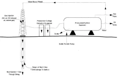
Proper fluids handling procedures are critical during underbalanced drilling operations.5 The
closed system must allow for sample catching and safe venting of produced gases and must
allow rig personnel both to flow and kill the well under all operating conditions (drilling,
tripping, circulating, making connections, etc.).
The closed system should initially contain all liquids and gases.5 Well bore effluent must pass
through a properly sized and constructed separator vessel. Gas exits the vessel to a flare stack
equipped with an automatic ignition system and flame propagation blocks. Oil and water are
separated within the vessel and pumped to independent fluid gauging and storage facilities on
site.
Air, liquid nitrogen, on site-generated nitrogen, cleaned exhaust gas, or locally produced
methane can be used for injection with the liquid phase. Each alternative has physical and
economic constraints which must be analyzed to determine the appropriate injection gas for a
project. Any one gas source does not immediately preclude the use of any other gas source.5
Air. The use of air as a means to lower bottom hole pressure and therefore increase rate of penetration is well documented technology with a long history of success. It is important
to recognize, however, that air drilling technology is limited to drilling essentially "dry"
wells and does not accommodate the unloading of large volumes of oil or water from a
horizontal section.
7
inert properties and ready availability. Field experience has shown invoice costs for liquid
nitrogen to be as high as 25% of total drilling costs. Typically, high daily cost, including
volume used and associated pumping charges, often precludes the use of bulk nitrogen,
given the alternatives available in the market.
On site generated nitrogen. A very economical alternative to liquid nitrogen is the use of on site nitrogen-generation equipment. The economic affect of increased nitrogen rates no
longer exists, because nitrogen consumption and cost are no longer related. On
site-generated nitrogen is typically charged at a flat rate per day, up to the capacity of the unit.
Past experience using on site nitrogen generators has shown this level to be safe.
Corrosion has been observed due to oxygen in the presence of produced water. Detailed
corrosion studies complete with treatment programs should be performed where wells are
to be drilled in the presence of connate water.
Cleaned exhaust gas. Compression is required at the rig site to supply sufficient volumes of injection gas at standpipe pressure. After an effective filtration process,
exhaust gas from the compressor prime movers can be used as an inert injection gas.
This new technology appears to be a highly economic alternative to other sources of
injection gas.
Methane. Methane gas can be a viable alternative to inert gases. Economics are a function of predicted injection rates, location of gas source, and predicted time of use.
The operator must consider the cost of linking an existing sales line into a drilling
operation as well as the direct costs of burning sales gas at a flare.
Typically, low injection rates or short-duration drilling operations may preclude the use of
sales gas. Some advantages of using sales gas include its relative compatibility with
indigenous hydrocarbons and lack of corrosion concerns.5
2. Bottom Hole Flowing Pressure Model
9
Thus, from the model, the minimum backpressure given from the surface to circulate the drilling fluid can be modelled5
It happens when the GLR reaches the maximum value
For the maximum allowable pressure, it can be modelled as
Then, the ECD equation will be
3. Annulus Fluid Flow Model
Underbalanced drilling (UBD) has several advantages compared to conventional drilling. These advantages include the elimination of formation damage, higher penetration rate, reducing circulation loss and the possibility of actually producing hydrocarbons during the drilling process.7 It is generally accepted that the success of underbalanced drilling is dependent on maintaining the wellbore pressure in an operational window determined by the formation pressure, wellbore stability, and the capacity of the surface equipment. By using the model developed by Mousavi et al.7 , this paper provide an improve, comprehensive, mechanistic model for pressure prediction through a well during UBD operations.
11
incorporates the fluid properties and pipe size and thus is free of the limitations associated with empirical correlations.7
In underbalanced drilling conditions, the pattern of flow depends on the flow rate, fluid properties and annulus size.
Where:
; ;
;
In this work we consider five different patterns: dispersed bubble, bubble, slug, churn, and annular. Then we present models for prediction of pressure drop in bubbly and slug (churn) flow regime:7
1. Bubble to Slug Transition
Bubble flow is characterized by a gas phase distributed as small bubbles in continuous liquid phase. The drift flux approach provides a simple and accurate method for modeling the in-situ velocity of the gas phase relative to that of mixture. The density difference between the phases can give rise to a drift flux, which adds a drift velocity equal to the terminal rise velocity of the bubbles.
And ; then we have
or
When the rise velocity of discrete bubble is larger than the rise velocity of the Taylor bubble, bubble flow does not take place. This condition establishes a geometrical limitation for existence of bubble flow in the annuli;
Thus, transition of bubble to slug occurs by two criteria, which are: dan
2. Transition Dispersed-Bubble Flow
At high flow rates, shear stress caused by turbulence tends to break up the larger bubbles inhibiting the transition to slug flow even when the void fraction exceeds the value of 0.25. The dispersed bubble flow, resulting from such dispersion of larger bubbles:
In the equation above, if the right terms show a larger value than the left term then the flow would be a dispersed bubble flow.
The second condition for this transition is presented here:
and
3. Slug to Churn Transition
13
Where Vd is the drift-flux velocity or the Taylor bubble rise velocity and is given by Bendiksen as:
Where . If then the flow would be in churn pattern. Owen model stated that:
4. Transition from Annular to Churn or Slug
Although annular regime is not likely to happen in the annuli, there are some specific conditions in which gas velocity needs to be increased in order to keep the underbalanced conditions. This model considers three conditions for transformation to annular regime:
Instability in the film occurs when:
Where
Ansari et al. has found the correlation to find
The model above is used for low gas velocities condition. For high gas velocities region, we use:
To predict the fluid flow behavior in the annuli, we will use the following models:6
1) Bubble Flow Model
Assuming a turbulence velocity profile for the mixture with rising bubbles concentrated more at the center than along the pipe wall, the slip velocity can be expressed as
If bubble swarm and inclination angle effects are considered rigorously, the following slip-velocity expression can be obtained:
Then, after obtaining we can estimate the mixture properties
15
Where is Moody friction factor obtained from :
2) Slug Flow Model
Generally, liquid mass balance can be written as
Applying a mixture volumetric balance over the cross section in the liquid slug and assuming constant phase densities, the following expression can be obtained:
The amount of liquid that moves upstream relative to the bubble nose is the same as the liquid that is overrun by the liquid slug. The exchange can be expressed in volumetric terms as
The translational velocity is generally considered as the sum of the velocity of a single elongated bubble in a stagnant liquid and the centerline velocity in the liquid slug
For inclined pipe flow, Bendiksen has proposed the following drift velocity correlation:
The following equation is used to estimate the gas velocity in the liquid slug:
Based on the overall gas mass balance, the closure relationship has been modified for deviated wells and given as:
Therefore the total pressure gradient over the entire unit is given by:
The liquid slug density is given by:
4. Result and Discussion
Bottom Hole Model
Formation damage and heavy circulation losses represent critical factors for drilling, testing and completion of depleted reservoir.11 In mature fields like belayim oil field in Egypt operating under depletion zones that exists between high pressurized shale causes a serious drilling problems such as differential sticking, drilling fluid loss to the formation and hole packed off due to shale movements.
A complete study was made prior to drilling the horizontal section 6” diameter in zone III of
well 122-78H, while maintaning under-balanced conditions in the wellbore. The sandstone pressure of zone III was estimated to be 3000-3500 psi which was suitable for UBD application. Zone III is an oil bearing sandstone reservoir lying at approximately 2350 mVD,
it’s approximately 3m thick.
The primary objectives of applying the UBD technique in Belayim field were to:11 1. minimize formation damage caused by fluid invasion in the near wellbore zone
2.eliminate conventional drilling problems such as differential pipe sticking and drilling fluid loss to the formation.
17
Bottom hole pressure measurement from two wells drilled with stable foams in the Parana Basin, Brazil, are compared with results given by model based on mechanical energy equation6. The first well is Well FR-1 located in the Alta Tres Pinheiros in Santa Catarina sate. A 12-1/4” hole section was drilled with jointed drill pipe. Bottom hole pressure measurements from 860 to 884 meters were reported. With a 130 gpm of mud rate and 380 scfm nitrogen injection rate, the measured bottom hole pressures are equivalent to 5.6 to 5.8 ppg of ECD at depth from 868 to 870 meters. The equation gives and ECD 5.72 ppg for this condition. The difference is 2.1%.
The second well is Well BB-1, which also has a 12-1/4” hole section drilled with nitrogen foam from 152 to 1300 meters. The average flow rate of gas and liquid varied as the well got deeper from 350 scfm of N2 and 200 gpm of fresh water at 152 meters to 700 scfm of N2 and 200 gpm of fresh water at 1300 meters. A reported ECD value is 5.0 ppg in average. The equation gives an ECD range from 4.05 to 5.46 ppg. The maximum difference is 9.2%.
Based on the comparison of those two wells, the newly developed model believed to be valid for foam drilling hydraulics calculation. Further validation of the model is definitely desirable if more pressure measurements are available in the future.
The Annulus Fluid Flow Model has been used for 20 wells drilled in condensate reservoirs. Since the downhole pressure data has been available, Ansari, Hasan and Kabir and couple of the traditional models were tested in compare to the new model. The error analysis results indicate that the present model decreases the error in pressure prediction through the annuli.
As one can find in previous works, modified Ansari method has been accepted as the most accurate and most general approach. However, the modified Ansari model fails for high velocity gas flow. In this work the drawback of Ansari Model has been removed by presenting another correlation for estimating the minimum dimensionless film thickness. The errors associated with the modified Ansari model were in some cases seen higher than the tolerance accepted for UBD control. It is speculated that the work presented here in is more accurate and can be applied with more confidence inside the operating window.
19
Real data of downhole pressure was plotted against our model results in Fig. 16 and 17 for 7 and 13 wells respectively and as it shows a good agreement between the model and the field data. The new model could be used for these and other similar oil and gas reservoirs.
Flow Annulus Model
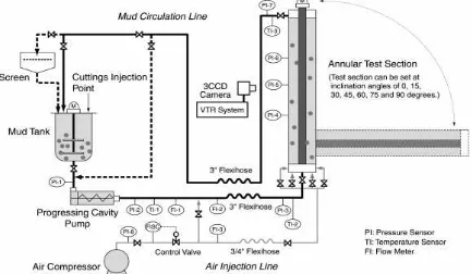
The Numerical model was run to generate results for a variety of hydrodynamic conditions, including fluid rheology, mud rate and viscosity, and cuttings size9.The result were analyzed and compared to experimental data obtained from a cutting transport flow loop system
(CTFLS) at TRC/JNOC’s Kashiwazaki Test Facility in Japan. Masuda et al7. Provided a comprehensive description of the experimental apparatus and procedure to determine the cuttings velocity and concentration values inside the test section. Fig. 2 is a schematic drawing of the flow loop. The annular test section was 9 m long, and consisted of a 5-in. (127.0 mm) ID transparent acrylic outer pipe ( borehole or casing). A 2.063 –in. (52.4 mm) or 2.875-in (73.0 mm ) OD steel inner pipe (drill pipe) was used. The test section was mounted on a movable frame, and the inclination of test section could be set an angle ranging from 0 (horizontal) to 90o (vertical) in 15o increments. Drillpipe eccentricity could be changed from 0 to 100%. Inner drillpipe could rotate at speeds ranging from 0 to 80 rpm.Q.T. Doan et al9
21
electromagnetic flow-meter. The mud flowed through the annulus in the transparent test section and returned to the mud tank. The mud circulation lines were made of 3-in. (7.62 mm) fixed and flexible pipes. Four pressure transducers and one temperatur sensor were mountd along the test section. Other Pressure and temperature sensors and flow meters were positioned at different points in the loop. Water and polyacrylamide solutions wew used to simulate drilling mud, and ceramic beads with average diameter of either 0.732 cm (~0.25 in.) or 0.366 cm (~0.125 in.) were used to simulate drilled cuttings. The moving behavior of cuttings at both steady-state and unsteady-state flow conditions was recorded by a CCD video camera system. The captured images were analyzed to obtain the velocity profile, cross-sectional distribution, and average velocity of cuttings in the annulus. Table 1 provides a summary of the experimental conditions, as well as data used in the simulation runs. Q.T. Doan et al 8The simulation was run for duration of 201 seconds of simulated time. The mud flow rat was 40 m3/hour, and drill cuttings were introduced into the test loop at a rate of 2.148 l/min (corresponding worked out to be approximately 0.3 % (volume). Initially, there was no deposit bed inside the annulus, and the cuttings were fully suspended at the inlet. The following is offerd to explain the phenomena associated with the behavior observed in the simulation results. A stationary bed formed locally as friction forces (owing to increased wall contact) coutered the momentum of a growing deposit bed. The onset of a stationary bed developed at a stagnation point. At this point, the friction forces were greater than the local driving forces (from interfacial stress, bulk momentum transfer, and pressure gradient). Bed particles accumulated locally as a result of particles decelerations. Q.T. Doan et al 9
Average Percent Error
The evaluation of the model has been carried out based on the following statistical parameters:6
E1 indicates the overall trend of the performance.
Absolute Average Percent Error
5. Conclusion
1. The new model is accurate enough for planning underbalanced drilling. The maximum difference between model-predicted and field-measured bottom hole pressure is 9.2% 2. Injection GLR is a dominating factor affecting depth limit and ECD for underbalanced
drilling fluid using gas mixture.
3. A new mechanistic model has been developed for UBD modeling in the annulus for vertical and diretional wells. In addition, the newly presented model corrects the transition from churn to annular regime to become more accurate and effective.
References
1) Regen, N. van. “Horizontal Underbalanced Drilling”. PETSOC-97-08-GE1, Petroleum Society of Canada. 1997
2) Bennion,D.B., Thomas, F.B., Bietz, R.F., Bennion, D.W., “Underbalanced Drillng,
Praises and Perils”, Paper SPE 35242, this paper was presented for presentation at the
SPE Permian Basin Oil &Gas Recovery Conference, March 27-29, 1996, Midland, Texas. 3) Luo, Shiying,. “A New Drill-In Fluid Used for Successful Underbalanced Drilling”, SPE
58800 Exploration Bureau, China, 2008.
4) David, Amiel, et al.”The Rheology of foam”, SPE 2544, this paper was prepared for the 44th annual fall meeting of the SPE of AIME, to be held in Denver, Colo., 28 October 1969.
5) Boyun Guo, “A Closed FormHydraulics Equation for Predicting Bottom Hole Pressure in
UBD with Foam”. IADC/SPE 81640 MS presented at IADC/SPE Underbalanced
Techmology Conference and Exhibition, March 25 – 26, 2003, Houston, Texas
6) Mousavi, H, and Mostafavi, V,. “Modeling of Three-Phase Flow in the Annuli During
UBD Operations”, SPE 112679 presented at the International Symposium and Exhibition
on Formation Damage Control held in Lafayette, Lousiana, U.S.A., 13-15 February 2008. 7) Masuda, Y. et all.: “Experimental Study to Determined Critical Flow Rate of Cuttings
Transport During Underbalanced Drilling,” paper IADC/SPE 62737 presented at he 2000
IADC/SPE Asia Pacific Drilling Technology Conference, Kuala Lumpur, 11-13 September.
8) Gregory, G. A. : “Foam Flow Modelling for UBD Applications”. PETSOC-03-05-DAS 9) Q.T. Doan., et all,.: “Modelling of Transient Cuttings Transport in Underbalanced
Drilling (UBD)”
10) Emam,M., Mohsen,A., and Romani,S. “Well 112-78H UBD operations case history”, OMC 2003-055, this paper was presented for presentation at the Offshore Mediterranean Conference and Exhibition, March 26-28,2003, Ravenna , Italy
11) Marbun, B. T. H. et al. “A Methodology of underbalanced drilling design in depleted