MOBILE
TELECOMMUNICATIONS
PROTOCOLS FOR
DATA NETWORKS
MOBILE
TELECOMMUNICATIONS
PROTOCOLS FOR
DATA NETWORKS
Anna Ha´
c
West Sussex PO19 8SQ, England Telephone (+44) 1243 779777
Email (for orders and customer service enquiries): [email protected] Visit our Home Page on www.wileyeurope.com or www.wiley.com
All Rights Reserved. No part of this publication may be reproduced, stored in a retrieval system or transmitted in any form or by any means, electronic, mechanical, photocopying, recording, scanning or otherwise, except under the terms of the Copyright, Designs and Patents Act 1988 or under the terms of a licence issued by the Copyright Licensing Agency Ltd, 90 Tottenham Court Road, London W1T 4LP, UK, without the permission in writing of the Publisher. Requests to the Publisher should be addressed to the Permissions Department, John Wiley & Sons Ltd, The Atrium, Southern Gate, Chichester, West Sussex PO19 8SQ, England, or emailed to [email protected], or faxed to (+44) 1243 770571. This publication is designed to provide accurate and authoritative information in regard to the subject matter covered. It is sold on the understanding that the Publisher is not engaged in rendering professional services. If professional advice or other expert assistance is required, the services of a competent professional should be sought.
Other Wiley Editorial Offices
John Wiley & Sons Inc., 111 River Street, Hoboken, NJ 07030, USA Jossey-Bass, 989 Market Street, San Francisco, CA 94103-1741, USA Wiley-VCH Verlag GmbH, Boschstr. 12, D-69469 Weinheim, Germany
John Wiley & Sons Australia Ltd, 33 Park Road, Milton, Queensland 4064, Australia
John Wiley & Sons (Asia) Pte Ltd, 2 Clementi Loop #02-01, Jin Xing Distripark, Singapore 129809 John Wiley & Sons Canada Ltd, 22 Worcester Road, Etobicoke, Ontario, Canada M9W 1L1
British Library Cataloguing in Publication Data
A catalogue record for this book is available from the British Library ISBN 0-470-85056-6
Typeset in 10/12pt Times by Laserwords Private Limited, Chennai, India Printed and bound in Great Britain by TJ International, Padstow, Cornwall
Contents
Preface ix
About the Author xiii
1 Mobile Agent Platforms and Systems 1
1.1 Mobile Agent Platforms 1
1.1.1 Grasshopper 2
1.1.2 Aglets 2
1.1.3 Concordia 3
1.1.4 Voyager 3
1.1.5 Odyssey 3
1.2 Multiagent Systems 3
1.2.1 Agent-based load control strategies 5
1.3 Summary 9
Problems to Chapter 1 10
2 Mobile Agent-based Service Implementation, Middleware,
and Configuration 11
2.1 Agent-based Service Implementation 11
2.2 Agent-based Middleware 17
2.3 Mobile Agent-based Service Configuration 23
2.4 Mobile Agent Implementation 28
2.5 Summary 29
Problems to Chapter 2 29
3 Wireless Local Area Networks 33
3.1 Virtual LANs 33
3.1.1 Workgroup management 35
3.1.2 Multicast groups 36
3.2 Wideband Wireless Local Access 37
3.2.1 Wideband wireless data access based on OFDM
and dynamic packet assignment 37
3.2.2 Wireless services support in local multipoint distribution
3.2.3 Media Access Control (MAC) protocols for wideband
wireless local access 41
3.2.4 IEEE 802.11 41
3.2.5 ETSI HIPERLAN 44
3.2.6 Dynamic slot assignment 46
3.3 Summary 50
Problems to Chapter 3 51
4 Wireless Protocols 55
4.1 Wireless Protocol Requirements 56
4.2 MAC Protocol 56
4.3 Broadband Radio Access Integrated Network 58
4.4 Hybrid and Adaptive MAC Protocol 59
4.5 Adaptive Request Channel Multiple Access Protocol 60
4.6 Request/Acknowledgement Phase 61
4.7 Permission/Transmission Phase 62
4.8 Performance Analysis 65
4.9 Performance Measures 67
4.10 Summary 69
Problems to Chapter 4 70
5 Protocols for Wireless Applications 73
5.1 Wireless Applications and Devices 73
5.2 Mobile Access 79
5.3 XML Protocol 80
5.4 Data Encapsulation and Evolvability 82
5.5 Wireless Application Protocol (WAP) 85
5.6 Summary 88
Problems to Chapter 5 89
6 Network Architecture Supporting Wireless Applications 93
6.1 WAE Architecture 93
6.2 WTA Architecture 98
6.3 WAP Push Architecture 105
6.4 Summary 109
Problems to Chapter 6 109
7 XML, RDF, and CC/PP 111
7.1 XML Document 111
7.2 Resource Description Framework (RDF) 114
7.3 CC/PP – User Side Framework for Content Negotiation 119
7.4 CC/PP Exchange Protocol based on the HTTP Extension
Framework 129
7.6 Summary 135
Problems to Chapter 7 135
8 Architecture of Wireless LANs 139
8.1 Radio Frequency Systems 140
8.2 Infrared Systems 141
8.3 Spread Spectrum Implementation 141
8.3.1 Direct sequence spread spectrum 141
8.3.2 Frequency hopping spread spectrum 142
8.3.3 WLAN industry standard 142
8.4 IEEE 802.11 WLAN Architecture 143
8.4.1 IEEE 802.11a and IEEE 802.11b 145
8.5 Bluetooth 146
8.5.1 Bluetooth architecture 147
8.5.2 Bluetooth applications 152
8.5.3 Bluetooth devices 154
8.6 Summary 157
Problems to Chapter 8 158
9 Routing Protocols in Mobile and Wireless Networks 163
9.1 Table-driven Routing Protocols 164
9.1.1 Destination-sequenced distance-vector routing 164
9.1.2 The wireless routing protocol 166
9.1.3 Global state routing 166
9.1.4 Fisheye state routing 167
9.1.5 Hierarchical state routing 167
9.1.6 Zone-based hierarchical link state routing protocol 168
9.1.7 Cluster-head gateway switch routing protocol 168
9.2 On-demand Routing Protocols 169
9.2.1 Temporally ordered routing algorithm 169
9.2.2 Dynamic source routing protocol 171
9.2.3 Cluster-based routing protocol 173
9.2.4 Ad hocon-demand distance-vector routing 174
9.2.5 Signal stability-based adaptive routing 175
9.2.6 Associativity-based routing 176
9.2.7 Optimized link state routing 177
9.2.8 Zone routing protocol 177
9.2.9 Virtual subnets protocol 178
9.3 Summary 179
Problems to Chapter 9 179
10 Handoff in Mobile and Wireless Networks 181
10.1 Signaling Handoff Protocol in WATM Networks 184
10.3 Rerouting Methods 187
10.4 Optimized COS Discovery through Connection Grouping 188
10.5 Schedule-assisted Handoffs 189
10.6 Handoff in Low Earth Orbit (LEO) Satellite Networks 189
10.7 Predictive Reservation Policy 190
10.8 Chaining Approaches 191
10.8.1 Hop-limited handoff scheme 191
10.8.2 Chaining followed by make-break 191
10.9 Analysis of Chaining Handoff Approaches 193
10.10 Summary 194
Problems to Chapter 10 194
11 Signaling Traffic in Wireless ATM Networks 197
11.1 A Model of WATM Network 197
11.2 Chain Routing Algorithm 199
11.3 Implementation of the Handoff Scheme 202
11.4 Analysis of the Chain Routing Algorithm 203
11.4.1 Comparison of chain routing algorithm with hop-limited
method 203
11.4.2 Analysis of the signaling traffic cost 205
11.4.3 Handoff latency 207
11.5 Summary 210
Problems to Chapter 11 210
12 Two-phase Combined QoS-based Handoff Scheme 213
12.1 Wireless ATM Architecture 214
12.2 Mobility Support in Wireless ATM 217
12.3 Comparison of Rerouting Schemes 222
12.4 Maintaining the Cell Sequence During Path Optimization 224
12.5 Combined QoS-based Path Optimization Scheme 227
12.6 Summary 230
Problems to Chapter 12 230
References 233
Preface
Mobile telecommunications emerged as a technological marvel allowing for access to personal and other services, devices, computation and communication, in any place and at any time through effortless plug and play. This brilliant idea became possible as the result of new technologies developed in the areas of computers and communications that were made available and accessible to the user.
This book describes the recent advances in mobile telecommunications and their pro-tocols. Wireless technologies that expanded to a wide spectrum and short-range access allow a large number of customers to use the frequency spectrum when they need it. Devices are used to communicate with the expanded network. Software systems evolved to include mobile agents that carry service information that is compact enough to be implemented in the end user devices.
The area of mobile telecommunications has been growing rapidly as new technologies emerge. Mobile users are demanding fast and efficient connections that support data applications. Extending wireless access to the applications requires creating mobile agents, systems, and platforms to implement service configuration. Wireless Local Area Networks (LANs) supporting a growing number of users and applications require wideband wireless local access, wireless protocols, and virtual LANs. Wireless applications require protocols and architecture supporting these applications. Wireless connection has to be provided by the networks and protocols. Mobile networks must function efficiently by using their protocols, performing routing and handoff for mobile users.
This book focuses on the newest technology for mobile telecommunications support-ing data applications. The book provides a real application-oriented approach to solvsupport-ing mobile communications and networking problems. The book addresses a broad range of topics from mobile agents and wireless LANs to wireless application protocols, wireless architecture, and mobile networks.
The goal of this book is to explain how to support modern mobile telecommunications, which evolve toward value-added, on-demand services, in which the need for communica-tion becomes frequent and ongoing, and the nature of the communicacommunica-tion becomes more complex. Mobile agents are used to enable on-demand provision of customized services. Examples of mobile agent-based service implementation, middleware, and configuration are introduced.
Mobile applications are supported by wireless LANs. Virtual LANs provide support for workgroups that share the same servers and other resources over the network.
Orthogonal Frequency Division Multiplex (OFDM) allows individual channels to main-tain their orthogonality, or distance, to adjacent channels. This technique allows data symbols to be reliably extracted and multiple subchannels to overlap in the frequency domain for increased spectral efficiency. The IEEE 802.11 standards group chose OFDM modulation for wireless LANs operating at bit rates up to 54 Mb s−1 at 5 GHz.
Wideband Code Division Multiple Access (WCDMA) uses 5-MHz channels and sup-ports circuit and packet data access at 384 kb s−1 nominal data rates for macrocellular wireless access. WCDMA provides simultaneous voice and data services. WCDMA is the radio interface technology for Universal Mobile Telecommunications System (UMTS) networks.
Mobile applications and wireless LANs use wireless protocols. A Media Access Control (MAC) protocol for a wireless LAN provides two types of data-transfer Service Access Points (SAP): network and native. The network SAP offers an access to legacy network protocols [e.g., IP (Internet Protocol)]. The native SAP provides an extended service interface that may be used by custom network protocols or user applications capable of fully exploiting the protocol-specific QoS parameters within the service area.
Limitations of power, available spectrum, and mobility cause wireless data networks to have less bandwidth and more latency than traditional networks, as well as less connection stability than other network technologies, and less predictable availability.
Mobile devices have a unique set of features that must be exposed into the World Wide Web (WWW) in order to enable the creation of advanced telephony services such as location-based services, intelligent network functionality, including integration into the voice network, and voice/data integration.
The Wireless Application Protocol (WAP) architecture provides a scalable and exten-sible environment for application development for mobile communication devices. The WAP protocol stack has a layered design, and each layer is accessible by the layers above and by other services and applications. The WAP layered architecture enables other ser-vices and applications to use the features of the WAP stack through a set of well-defined interfaces. External applications can access the session, transaction, security, and transport layers directly.
The network architecture supporting wireless applications includes Wireless Appli-cations Environment (WAE), Wireless Telephony Application (WTA), and WAP Push framework. The WAE architecture is designed to support mobile terminals and network applications using different languages and character sets.
The WAP Push framework introduces a means within the WAP effort to transmit information to a device without a previous user action. In the client/server model, a client requests a service or information from a server, which transmits information to the client. In this pull technology, the client pulls information from the server.
Extensible Markup Language (XML) is an application profile or restricted form of the Standard Generalized Markup Language (SGML). XML describes a class of data objects called XML documents and partially describes the behavior of computer programs that process them. Resource Description Framework (RDF) can be used to create a general, yet extensible, framework for describing user preferences and device capabilities. This information can be provided by the user to servers and content providers. The servers can use this information describing the user’s preferences to customize the service or content provided.
A Composite Capability/Preference Profile (CC/PP) is a collection of the capabilities and preferences associated with the user and the agents used by the user to access the World Wide Web (WWW). These user agents include the hardware platform, system software, and applications used by the user.
In a wireless LAN, the connection between the client and the user exists through the use of a wireless medium such as Radio Frequency (RF) or Infrared (IR) communications. The wireless connection is most usually accomplished by the user having a handheld terminal or a laptop computer that has an RF interface card installed inside the terminal or through the PC (personal computer) card slot of the laptop. The client connection from the wired LAN to the user is made through an Access Point (AP) that can support multiple users simultaneously. The AP can reside at any node on the wired network and performs as a gateway for wireless users’ data to be routed onto the wired network.
A wireless LAN is capable of operating at speeds in the range of 1 or 2, or 11 Mbps depending on the actual system. These speeds are supported by the standard for wireless LAN networks defined by the international body, the IEEE.
The network communications use a part of the radio spectrum that is designated as license-free. In this band, of 2.4 to 2.5 GHz, the users can operate without a license when they use equipment that has been approved for use in this license-free band. The 2.4-GHz band has been designated as license-free by the International Telecommunications Union (ITU) and is available for use, license-free in most countries in the world.
The ability to build a dynamically scalable network is critical to the viability of a wireless LAN as it will inevitably be used in this mode. The interference rejection of each node will be the limiting factor to the expandability of the network and its user density in a given environment.
In ad hoc networks, all nodes are mobile and can be connected dynamically in an arbitrary manner. All nodes of these networks behave as routers and take part in discovery and maintenance of routes to other nodes in the network.
An ad hoc network is a collection of mobile nodes forming a temporary network without the aid of any centralized administration or standard support services available in conventional networks.
join the network or existing nodes may leave or be turned off.Ad hoc routing protocols must minimize the time required to converge after the topology changes.
The ad hoc routing protocols can be divided into two classes: table-driven and on-demand routing on the basis of when and how the routes are discovered. In table-driven routing protocols, consistent and up-to-date routing information to all nodes is maintained at each node, whereas in on-demand routing, the routes are created only when desired by the source host.
When the mobile end user moves from one AP to another AP, a handoff is required. When the handoff occurs, the current QoS may not be supported by the new data path. In this case, a negotiation is required to set up new QoS. Since a mobile user may be in the access range of several APs, it will select the AP that provides the best QoS. During the handoff, an old path is released and then a new path is established. Connection rerouting schemes must exhibit low handoff latency, maintain efficient routes, and limit disruption to continuous media traffic while minimizing reroute updates to the network switches and nodes.
Basically, there are three connection rerouting approaches: full connection establish-ment, partial connection re-establishestablish-ment, and multicast connection re-establishment.
In the wireless Asynchronous Transfer Mode (ATM) network, a radio access layer provides high-bandwidth wireless transmission with appropriate medium access control and data link control. A mobile ATM network provides base stations (access points) with appropriate support of mobility-related functions, such as handoff and location management.
QoS-based rerouting algorithm is designed for the two-phase interswitch handoff scheme for wireless ATM networks. Path extension is used for each inter-switch handoff, and path optimization is invoked when the handoff path exceeds the delay constraint or maximum path extension hops constraint. The path optimization schemes include combined QoS-based, delay-QoS-based, and hop-based path rerouting schemes.
The content of the book is organized into 12 chapters as follows:
Chapter 1 introduces mobile agents and presents platforms and systems to imple-ment agent-based services in the network. Chapter 2 describes mobile agent-based service implementation. Mobile agent-based middleware and service configuration are introduced. Mobile agent implementation is discussed.
Chapter 3 describes wireless LANs, introduces virtual LANs, and presents wideband wireless local access. Chapter 4 describes wireless protocols.
Protocols for wireless applications are studied in Chapter 5. Wireless applications and devices are discussed and wireless application protocol is introduced. Network architecture supporting wireless applications is presented in Chapter 6. Extensible markup language, resource description framework, and composite capability/preference profile are described in Chapter 7.
Architecture of wireless LANs is studied in Chapter 8. The protocols supporting mobile communications, IEEE 802.11 and Bluetooth, are described.
About the Author
Anna Ha´c received her M.S. and Ph.D. degrees in Computer Science from the Department of Electronics, Warsaw University of Technology, Poland, in 1977 and 1982, respectively. She is a professor in the Department of Electrical Engineering, University of Hawaii at Manoa, Honolulu. During her long and successful academic career, she has been a visiting scientist at Imperial College, University of London, England, a postdoctoral fellow at the University of California at Berkeley, an assistant professor of electrical engineering and computer science at The Johns Hopkins University, a member of the technical staff at AT&T Bell Laboratories, and a senior summer faculty fellow at the Naval Research Laboratory.
Her research contributions include system and workload modeling, performance anal-ysis, reliability, modeling process synchronization mechanisms for distributed systems, distributed file systems, distributed algorithms, congestion control in high-speed networks, reliable software architecture for switching systems, multimedia systems, and wireless networks.
She has published more than 130 papers in archival journals and international con-ference proceedings and is the author of a textbookMultimedia Applications Support for Wireless ATM Networks (2000).
1
Mobile agent platforms
and systems
Advanced service provisioning allows for rapid, cost-effective service deployment. Mod-ern mobile telecommunications evolve towards value-added, on-demand services in which the need for communication becomes frequent and ongoing, and the nature of the commu-nication becomes more complex. The services of the future will be available ‘a la carte’, allowing subscribers to receive content and applications when they want it.
Introducing Mobile Agents (MAs) within the network devices, Mobile Stations (MSs), and Mobile Switching Centers (MSCs) provides the necessary flexibility into the network and enhanced service delivery. MAs enable on-demand provision of customized services via dynamic agent downloading from the provider system to the customer system or directly to the network resources. MAs have the capability to migrate between networks, to customize for the network, and to decentralize service control and management software by bringing control and managements agents as close as possible to the resources.
MAs can be used in mobile networks to support advanced service provisioning, as well as for personal communication, for mobility, and to support Virtual Home Environment (VHE). The VHE agent enables individually subscribed and customized services to follow their associated users to wherever they roam.
1.1 MOBILE AGENT PLATFORMS
Mobile Agent Technology (MAT) uses interworking between Mobile Agent Platforms (MAPs). Several MAPs are based on Java. These platforms are Grasshopper, Aglets, Concordia, Voyager, and Odyssey.
Each MAP has a class library that allows the user to develop agents and applications. The core abstractions are common to most platforms since they are inherent in the MA paradigm. These abstractions include agents, hosts, entry points, and proxies.
• Agents: In each platform, a base class provides the fundamental agent capability. In some platforms this base class is used for all agents (static and mobile) while in others there are two separate classes.
• Hosts: The termshosts,environments,agencies,contexts,servers, andAgentPlacesare used to refer to the components of the framework that must be installed at a computer node and that provide the necessary runtime environment for the agents to execute. • Entry points: The agents have to save the necessary state information to member
variables, allowing the entry point method to proceed depending on the state of the computation. Platforms may have one or multiple entry points.
• Proxies: The proxy is a representative that an MA leaves when migrating from a node, and it can be used to forward messages or method invocations to an MA in a location-independent manner. Platforms may implement proxies in different ways. A significant difference is whether the arbitrary methods of an agent can be called remotely through the proxy. Platforms that support this functionality provide a utility that parses a MA’s class and creates a corresponding proxy. In platforms where arbitrary Remote Method Invocation (RMI) through a proxy is not supported, the proxy object provides only a uniform, generic method to send messages, and therefore no proxy-generation utility is required.
1.1.1 Grasshopper
The Grasshopper platform consists of a number of agencies (hosts) and a Region Registry (a network-wide database of host and agent information) remotely connectedviaan Object Request Broker (ORB). Agencies represent the runtime environments for MAs. Several agencies can be grouped into one region represented by a region registry.
Remote interactions between the components of the Distributed Agent Environment (DAE) are performedviaan ORB. The Grasshopper’s Communication Service is a part of each agency and region registry. The Grasshopper supports the following protocols: plain sockets (with or without Secure Socket Layer, SSL), Common Object Request Broker Architecture (CORBA) Internet Inter – ORB Protocol (IIOP), and RMI – with or without SSL. Support for more protocols can be integrated into the communication service.
The Grasshopper platform conforms to the Object Management Group’s (OMG) Mobile Agent System Interoperability Facility (MASIF) standard.
1.1.2 Aglets
Aglets (Agent applets) were developed by the IBM Tokyo Research Laboratory. The Aglets class library provides an Application Programming Interface (API) that facilitates the encoding of complex agent behavior. Particularly, the way the behavior of the base Aglet class is extended resembles the way Web applets are programmed. Aglets can cooperate with web browsers and Java applets.
reside. The core Aglet runtime is independent of the transport protocol and accesses ATP through a well-defined interface. Aglets use an interface, derived from MASIF standard, for the internal communication between the runtime core and the communication system, but do not export this interface as an external CORBA interface. The latest version of Aglets supports ATP and RMI. A CORBA IIOP –based transport layer will be provided in the future release of Aglets.
1.1.3 Concordia
Concordia was developed by Mitsubishi Electric Information Technology Center, USA. The main component of the Concordia system is the Concordia server that provides for the necessary runtime support. The server consists of components integrated to create MA framework.
Concordia uses TCP/IP communication services. The communication among agents and their migration employs Java’s RMI, where standard sockets are replaced by secure sockets (SSL).
1.1.4 Voyager
Voyager developed by ObjectSpace is a Java-based MA system. Voyager relies exclu-sively on the services of its supporting ORB. The core functionality of an ORB is to facilitate interobject communication by shuttling messages to and from remote objects and instantiating persistent distributed objects. Voyager’s ORB can facilitate only Java objects, and this is not an OMG-compatible ORB.
Features supported by the Voyager’s ORB include migration of both agents and arbi-trary Java object (a feature that does not exist in other MAPs), the ability to remote-enable (instantiate) a class, remote execution of static methods, multicast messaging, synchronous messages, and time-dependent garbage collection. ObjectSpace has implemented hooks in the Voyager to support interworking with other ORBs.
1.1.5 Odyssey
Odyssey is a Java-based MAP implemented by General Magic. Odyssey uses Java’s RMI for communication between Agents. The transport mechanism used for Agent migration can be CORBA IIOP, Distributed Component Object Model (DCOM), or RMI. Agents cannot call remotely the methods of other Agents but can engage with them in a meeting.
1.2 MULTIAGENT SYSTEMS
The Intelligent Network (IN) was developed to introduce, control, and manage services rapidly, cost effectively, and in a manner not dependent on equipment and software from particular equipment manufactures. The architecture of an IN consists of the following node types: Service Switching Points (SSPs), Service Control Points (SCPs), Service Data Points (SDPs), and Intelligent Peripherals (IP). These nodes communicate with each other by using a Signaling System No. 7 (SS7) network. SSPs facilitate end user access to services by using trigger points for detection of service access codes. SCPs form the core of the architecture; they receive service requests from SSPs and execute the service logic. SCPs are assisted by SDPs, which store service/customer related data, and by IPs, which provide services for interaction with end users (e.g., automated announcements or data collection).
IN overloads occur when the load offered to one or more network resources (e.g., SCP processors) exceeds the resource’s maximum capacity. Because of the central role played by the SCP, the overall goal of most IN load control mechanisms is to protect SCP processors from overload. The goal is to provide customers with high service availability and acceptable network response times, even during periods of high network loading. Load control mechanisms are designed to be
• efficient– keeping SCP utilization high at all times;
• scalable– suited to all networks, regardless of their size and topology;
• responsive– reacting quickly to changes in the network or offered traffic levels; • fair– distributing system capacity among network users and service providers in a
manner deemed fair by the network operator;
• stable– avoiding fluctuations or oscillations in resources utilization; • simple– in terms of ease of implementation.
The majority of IN load control mechanisms are node-based, focusing on protect-ing individual nodes in the network (typically SCPs) from overload. Jennprotect-ings et al. argue that node-based mechanisms cannot alone guarantee that desired Quality of Ser-vice (QoS) levels are consistently achieved. The following observations support this viewpoint:
• Most currently deployed node-based mechanisms were designed for standard telephony traffic patterns. Present and future INs support a large number of heterogeneous services, each exhibiting changing traffic characteristics that cannot be effectively controlled by using node-based techniques.
• Existing node-based overload protection mechanisms serve to protect individual nodes only and may cause the propagation of traffic congestion, resulting in adverse effects on the service completion rates of the network as a whole.
• Typically node-based mechanisms do not interact effectively with the protection mech-anisms that are incorporated into the signaling networks that carry information between the nodes in a network.
• Node-based controls typically focus on SCP protection only.
While flexible and adaptable network-based load control mechanisms can be imple-mented by using standard software engineering techniques, Jenningset al. argue that there are many advantages of adopting an agent-based approach:
• Methodology: The agent paradigm encourages an information-centered approach to application development; thus it provides a useful methodology for the development of control mechanisms that require manipulation of large amounts of data collected throughout the network.
• Agent communication languages: Advanced communication languages allow agents to negotiate in advance the semantics of future communications. This is not present in traditional communications protocols and can be used in mechanisms that adapt to dynamic network environments in which, for instance, traffic patterns change as a result of the introduction or withdrawal of services.
• Adaptivity: The agents adaptive behavior allows them to learn about the normal state of the network and better-judge their choice of future actions.
• Openness: Agents can exchange data and apply it in different ways to achieve a common goal. This means that equipment manufacturers can develop load control agents for their own equipment, but these agents can still communicate with agents residing in other equipment types.
• Scalability: The agent approach allows for increased scalability to larger networks. For instance, an agent associated with a recently introduced piece of equipment can easily incorporate itself into the agent community and learn from the other agents the range of parameters that it should use for its load control algorithm.
• Robustness: Agents typically communicate asynchronously with each other and thus are not dependent on the prompt delivery of interagent messages. The ability to act even during interrupted communications (e.g., due to overload or network failures) is a desirable attribute of a load control mechanism.
1.2.1 Agent-based load control strategies
The goal of the agent-based load control strategies is to allocate resources to the arriving user service requests in an optimal way. There are three classes of agents that carry out the tasks necessary to allocate IN resources in this optimal way:
• QUANTIFIERagents that monitor and predict the load and performance of SCP proces-sors (and possibly other IN resources) and report this information to the other agents; • DISTRIBUTOR agents that maintain an overview of the load and resource status in the entire network and can play a controlling and supervisory role in resource allocation; • ALLOCATOR agents that are associated with SSPs. They form a view of the load
situation in the network and the possibility of resource overload, based on their own predictive algorithms and information received from the other agents. If these agents perceive a danger of overload of resources, they throttle service requests on a prior-ity basis.
Q
Q Q
D
A A A
SS7 network SCP2
SCP1 SCPN
SSP2
SSP1 SSPM
• • • • • •
Q
A
D
Quantifier
Allocator
Distributor
Figure 1.1 Agent-based load control strategy.
SCPs, each supporting all service types, is shown in Figure 1.1 and is used to describe agent-based load control strategies.
Computational markets, as applied to resource allocation problems, are generally imple-mentations of the General Equilibrium Theory, developed in the field of microeconomics, whereby agents in the market set prices and create bids for resources, on the basis of demand-and-supply functions. Once equilibrium has been computed from the bids of all the agents, the resources are allocated in accordance with the bids and the equilibrium prices. The search for the market equilibrium can be implemented so that the customer and producer submit bids to an auctioneer. From these bids, the auctioneer updates its information and requests new bids in an iterative fashion. Once the market equilibrium has been found, the allocation of goods is performed in accordance with the bids and market prices.
In the market strategy, load control is carried out by means of tokens, which are sold by MB-QUANTIFIER agents (MB indicates that the agent implements part of a market-based strategy) of providers (SCP) and bought by MB-ALLOCATOR agents of customers (SSP). The amount of tokens sold by an SCP controls the load offered to it, and the amount of tokens bought by an SSP determines how many IN service requests it can accept. Trading of tokens in an auction is carried out so that the common benefit is maximized.
MB-QUANTIFIER bids consist of the unclaimed processing capability for the coming interval and the processing requirements for each service class. MB-ALLOCATOR bids consist of the number of expected IN service requests over the next interval for each service class. These values are set to the numbers that arrived in the previous interval as they are assumed to be reasonably accurate estimates.
The objective of the auction process is to maximize expected network profit over the next interval by maximizing the increase in expected marginal utility, measured as marginal gain over cost, for every token issued. The expected marginal gain associ-ated with allocating an additional token to an MB-ALLOCATOR is defined as the profit associated with consuming it times the probability that it will be consumed over the auction interval. The expected marginal cost associated with issuing a token from an MB-QUANTIFIER is defined as the ratio between the processing time consumed and the remaining processing time. On the basis of these values, the MB-DISTRIBUTOR imple-ments a maximization algorithm that is iterated to allocate all the available tokens. Tokens are typically allocated to MB-ALLOCATORS with higher bids (i.e., those that expect greater number of requests for service sessions that result in high profits) in preference to those with lower bids.
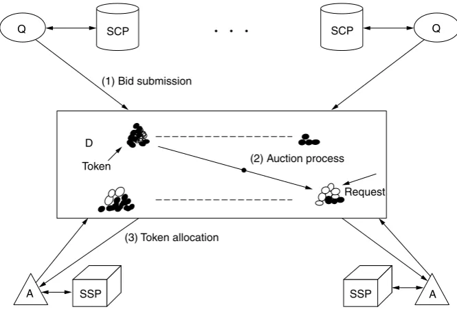
The operation of the auction algorithm in which there is only one service class sup-ported by the network is shown in Figure 1.2. In the first step, that is, Bid Submission, MB-QUANTIFIERS and MB-ALLOCATORS submit their bids to the MB-DISTRIBUTOR, which then executes the second step, that is, Auction Process. In this figure, dark circles represent tokens, whereas light circles represent token requests; the auction algorithm assigns tokens to token requests. Once the auction is completed, in the third step the
SCP
Q • • • SCP Q
(2) Auction process
(3) Token allocation (1) Bid submission
Request Token
D
A SSP SSP A
values of token assignments are reported to the MB-ALLOCATORS, which use them to admit service requests in the next time period.
The result of the auction process is that tokens are allocated to balance the arriving traffic load across all SCPs, subject to maximizing the overall network profit.
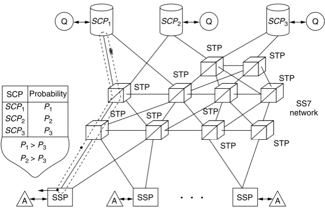
The following load control strategy is based on Ant Colony Optimization, which is the application of approaches based on the behavior of real ant colonies to optimization problems. The operation of ant-based IN load control strategy is shown in Figure 1.3.
At intervals of length T, a mobile agent AB-ANT, where AB indicates ant-based strategy, is generated for every service type at every SSP in the network and sent to a selected SCP. Each SSP maintains pheromone tables for each service type, which contain entries for all the SCPs in the network. These entries are the normalized probabilities,Pi for choosing SCPi as the destination for an ANT. The destination SCP of an AB-ANT is selected using the information in the pheromone table following either the normal scheme or the exploration scheme. The scheme used is selected at random, but with the probability of using the normal scheme much higher than the exploration scheme.
In the normal scheme, the SCP is selected randomly, the probability of picking SCPi being the probabilityPi indicated in the pheromone table. In the exploration scheme, the SCP is also selected randomly, and the probabilities of selecting all the SCPs are equal. The purpose of the exploration scheme is to introduce an element of noise into the system so that more performant SCPs can be found.
ANTS travel to the designated SCP, where they interact with the local AB-QUANTIFIER agent and then return to their originating SSP. They also keep track of the time they have spent traversing the network. AB-ANTS arriving at the SCP request information from the AB-QUANTIFIER on the currently expected average processing
STP
SCP1 SCP2 SCP3
P1
P1 > P3 P2 > P3 P2 P3
SCP1 SCP2 SCP3
STP STP
STP
STP
STP STP
STP STP
STP
A A A
Q Q
Q
SSP SSP SSP
SS7 network SCP
• •
•
• • Probability
times for the service type of interest. Processing times reported are the processing time for the initial message of the service session and the sum of the processing times for all other messages. The separation between the processing times for the initial and subse-quent messages is used to highlight the importance of the time spent processing the initial message, by which time the service user would not have received any response from the network. Reported processing times include those incurred in accessing information from databases, which may be held in SDPs in other parts of the network.
Upon return to the SSP, the ANT passes its gathered information to the AB-ALLOCATOR, which then updates the pheromone table entries for its service type, using the following formula.
Pi =
Pi+p 1+p
wherei indicates the visited SCP, andPi is the probability of choosing SCPi. The prob-abilityPj of choosing SCPj is
Pj=
Pj
1+p, j ∈[1, N], j =i
with
p= a
t1 + b t2 +
c t3 +
d t4 +e
where a, b, c, d, and e are constants; t1 is time-elapsed traveling SSP→SCP; t2 is
expected mean SCP processing time for initial message; t3 is expected mean SCP pro-cessing time for subsequent messages;t4 is time-elapsed traveling SCP→SSP.
The values of a, b, c, andd represent the relative importance the AB-ALLOCATOR gives to each of the four measurements. Requests for service are routed to the SCP that has the current highest priority value in the service’s pheromone table. Figure 1.3 illustrates that in normal load conditions the operation of the strategy will mean that SCPs with closer proximity to a source are more likely to be chosen as the destination for service requests, the reason being that the delays AB-ANTS experience in traveling to and from them are lower than for other SCPs.
1.3 SUMMARY
Each MAP has a class library that allows the user to develop agents and applications. The core abstractions are common to most platforms since they are inherent in the MA paradigm. These abstractions include agents, hosts, entry points, and proxies.
Agent-based technology offers a solution to the problem of designing efficient and flexible network management strategies. The OMG has produced the MASIF standard, which focuses on MA (object) technology, in particular, allowing for the transfer of agents code and state between heterogeneous agent platforms.
The majority of IN load control mechanisms are node-based, focusing on protecting individual nodes in the network (typically SCPs) from overload. Node-based mechanisms cannot alone guarantee that desired QoS levels are consistently achieved.
Flexible and adaptable network-based load control mechanisms can be implemented by using standard software engineering techniques. There are many advantages of adopting an agent-based approach, which include methodology, agent communication languages, adaptivity, openness, scalability, and robustness.
PROBLEMS TO CHAPTER 1
Mobile agent platforms and systems
Learning objectives
After completing this chapter, you are able to
• demonstrate an understanding of MAs; • discuss what is meant by MA platforms; • explain what agent-based technology is;
• demonstrate an improvement to network load control mechanisms; • explain what an intelligent network is;
• discuss the node-based and agent-based approach.
Practice problems
1.1: What are the core abstractions common to most platforms in the mobile agent paradigm?
1.2: What are the requirements for the load control mechanisms?
1.3: What are the advantages of using an agent-based approach to load control?
Practice problem solutions
1.1: The core abstractions common to most platforms in the mobile agent paradigm include agents, hosts, entry points, and proxies.
1.2: Load control mechanisms are designed to be efficient, scalable, responsive, fair, stable, and simple.
2
Mobile agent-based service
implementation, middleware,
and configuration
There are two agents groups: Intelligent Agents and Mobile Agents (MAs). Intelligent Agents have the ability to learn and react. MAs can migrate between different hosts, execute certain tasks, and collaborate with other agents.
In the Intelligent Network (IN) architecture, the control of the network resources is performed by the signaling plane, whereas the service creation, deployment, and provi-sioning is performed by the service plane. This separation allows introduction of new services and service features without changing the basic functionality of the network for the establishment and the release of resources such as calls and connections.
Traffic in the signaling network is reduced by moving services closer to the cus-tomers, and the messages related to service control are handled locally. The overhead of downloading service programs is done off-line and does not impact signaling performance. MAs enable both temporal distribution (i.e., distribution over time) and spatial distri-bution (i.e., distridistri-bution over different network nodes) of service logic.
MAs can be implemented in Java programming language. Additional features and mechanisms supported and envisioned in Jini programming language allow for imple-mentation of mobile devices in practical systems.
2.1 AGENT-BASED SERVICE IMPLEMENTATION
by the Telecommunications Information Networking Architecture (TINA) Consortium as the basis for the distributed architecture.
Mobile Agent Technology (MAT) uses the capabilities provided by machine-indepen-dent, interpreted languages like Java to deploy a framework in which applications can roam between network nodes maintaining their execution status. MAT platforms are often based on a CORBA DPE layer that allows distributed applications to dynamically recon-figure their layout according, for instance, to processing needs. This way certain MAs may have a CORBA interface enabling them to exploit the facilities offered by the distributed objects communication infrastructure.
This framework provides service designers with additional flexibility by using CORBA object location and object interfacing facilities, and by using code migration capabilities to dynamically upgrade network nodes with new applications.
The application of DOT and MAT to the IN architecture provides benefits to the service provisioning process as shown in Figure 2.1, with maintaining the basic principle of IN related to call and service separation.
The introduction of DOT and MAT at the service design and deployment level allows for reusability for easy and rapid deployment of services, extensibility towards new and updated services, and flexibility of service design. The adoption of DOT and MAT within the Service Switching Points (SSPs) allows for services distribution among the switches with faster handling of service requests, more reliable service execution, and network scalability.
In the IN architecture, the control of the network resources is performed by the signaling plane, whereas the service creation, deployment, and provisioning is performed by the service plane. This separation allows introduction of new services and service features
Intrinsic bottlenecks in
traditional IN can lead to poor
performances
New technologies for network unaware of distributed applications
High expenses in switching
design and maintenance
Mobile code supports dynamically reconfigurable network structures Adaptive broadband service provisioning architecture Open switching platforms able to accommodate mobile code
without changing the basic functionality of the network for the establishment and the release of resources such as calls and connections.
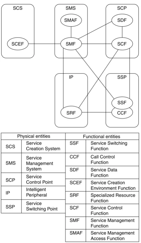
In the IN architecture, the intelligence is kept inside the core network that reduces the need to update the equipment of the Access Network (AN) representing the most widespread and expensive portion of the overall network. The IN architecture shown in Figure 2.2 comprises functional entities mapped into physical elements.
The communication between network entities is done through Signaling System No. 7 (SS7). The Intelligent Network Application Protocol (INAP) also uses SS7 for the IN
SCS SCEF SMS SMAF SMF SCP SDF SCF SSP SSF CCF IP SRF
Physical entities Functional entities
SCS SMS SCP IP Service Creation System Service Management System Service Control Point Intelligent Peripheral
SSP ServiceSwitching Point
SSF CCF SDF SCEF SRF SCF SMF SMAF Service Switching Function Call Control Function Service Data Function Service Creation Environment Function Specialized Resource Function Service Control Function Service Management Function Service Management Access Function
SMS SCE
SSP
TE TE TE TE
SSP
MAP 1
3 . . .n 2
ORB MAP
SCP SCP SCP
MAP MAP MAP
Signaling system #7
• • • • • •
Figure 2.3 Introduction of DOT and MAT in the IN for service design, deployment, and maintenance.
messages. IN architecture can support third-generation mobile systems and has the capacity of the third-party call setup between IN and the Internet.
Figure 2.3 illustrates how DOT and MAT are introduced at the service design, deploy-ment, and maintenance level. Services are designed as Java-based MAs in Service Creation Environments (SCEs) and then transferred to the Service Control Points (SCPs) by using capabilities provided by Mobile Agent Platforms (MAPs). In this architecture, SCPs contain CORBA and MAT in their design. Service providers benefit from a flexible service-provisioning environment by adopting object-oriented techniques for software design and by using MAT facilities to apply immediate and sophisticated policies for release distribution, update, and maintenance. Service Management System (SMS) stores and distributes services and manages the running service instances.
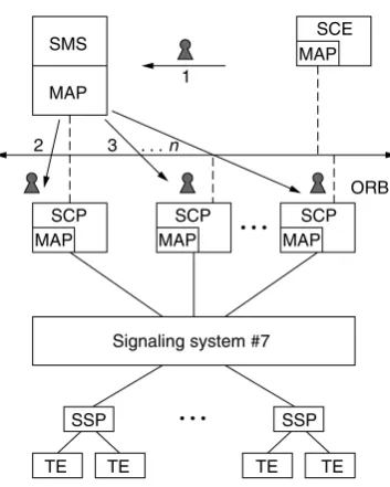
MAPs are introduced in the switching nodes. CORBA method invocations are used between SSPs and SCPs as an alternative to INAP as shown in Figure 2.4. The service logic (arrow 1) can be duplicated and distributed to the SCPs (arrows 2, 3,n), and directly to the SSPs. In this case, SS7 is only used for communication between SSPs.
This architecture with service distribution to the switches allows for faster handling of service requests, higher reliability in handing the services, scalability, and reduction of traffic in the signaling network.
SMS SCE
MAP 1
3 . . .n 2
ORB MAP
SCP SCP SCP
MAP MAP
TE TE
SSP MAP
TE TE
SSP MAP MAP
Signaling system #7
• • •
Figure 2.4 Introduction of MAPs in the IN switches.
The impact of network faults on the behavior of service is reduced since the network is accessed mainly to download the service logic. Network errors can occur during download-ing Service Location Protocols (SLPs) (i.e., agent migration) or durdownload-ing a Remote Method Invocation (RMI) (through CORBA infrastructure). These situations can be handled by using persistent mechanisms. Most MATs offer persistent agent facilities and, for CORBA objects, the Persistent Object Service (POS) can be used. This way service performance degradation is reduced.
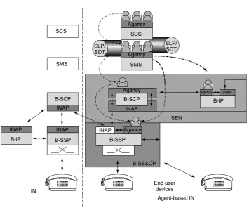
The problem of having centralized points is solved by distributing the service code across the network, which has a larger number of switches than SCPs. Dynamic SLP/SDT (Service Description Table) distribution allows IN services to be spread across the network to satisfy higher demand for those services. The distribution is performed dynamically when it is needed. In a distributed IN, the SLPs of the first IN calls are downloaded from the SMS to the SCP and then executed in the SCP. When the capacity of IN calls in SCP is exceeded, the SLPs are downloaded to the SSP, which must have the processing power and infrastructure to accomplish the new tasks (i.e., the SSP must also provide SCP functionality). This way the SCP can accommodate a higher number of calls and is restricted to the user interaction functionality [Broadband Special Resource Function (B-SRF) capability]. The distribution of the SLP to the attached SSPs can sustain the additional processing required per call.
7 F 89 R
45 6 1 0*2#3
7 F 89 R
45 6 1 0*2#3
7 F 89 R
45 6 1 0*2#3
Agency Agency SCS B-SCP SEN B-IP SLP/ SDT SMS SCS SMS INAP INAP INAP B-IP B-SCP B-SSP Agency Agency Agency INAP INAP B-SSP B-SS&CP INAP End user devices IN Agent-based IN SLP/ SDT
Figure 2.5 Distributed IN architecture.
between SSF and SCF, which is based on CORBA principles. Backward compatibility with traditional IN can be achieved by using IN/CORBA gateways, which allow for gradual introduction of distributed IN as advanced service islands. The distributed IN architecture is shown in Figure 2.5. In this figure, prefix B- is used with the IN functional entities to indicate the application of IN concepts to a broadband environment.
Broadband infrastructure is not a mandatory requirement and the benefits of MAT/DOT techniques to IN apply also to a narrowband architecture.
The following network elements are used in the network architecture: Service Creation System (SCS), SMS, Service Execution Node (SEN), Broadband Service Switching and Control Point (B-SS & CP), and Customer Premises Equipment. For broadband multime-dia services, the terminals need to have support to access switched broadband network (e.g., ATM). They need to have specialized hardware (e.g., ATM cards) and firmware (e.g., User to Network Interface – UNI signaling stack). MAT and CORBA can be applied to network physical entities including terminals.
has the capability to locally execute services downloaded from the network and is named B-SS & CP.
In distributed IN where CORBA can be used for message exchange, generic program-ming interfaces are available for developers. In this architecture, B-SCF, B-SDF, and B-SRF are implemented as CORBA-based software components allowing DPE’s location transparency and direct method invocation.
There are several benefits of distributed IN architecture. The network elements can communicate in a homogeneous way. The SEN can be the contact point between the users and the network. The operator can choose a distributed, centralized service or mixed service.
Interactive Multimedia Retrieval (IMR) is an integrated multimedia service within the framework of broadband IN. Broadband Video Telephone (BVT), is a real-time, multime-dia, two-party service that provides two geographically separated users with the capability of exchanging quality voice information, together with the transmission of high-quality video data. BVT is offered by Broadband-Integrated Services Digital Network (B-ISDN), which supports the facilities requested by the new generation of multimedia workstations.
The BVT service uses mobility management procedures to enable users to register at different (fixed) terminals. In a manner similar to the IMR and BVT services, the realization of these procedures is based on DOT and MAT.
MAs enable both temporal distribution (i.e., distribution over time) and spatial dis-tribution (i.e., disdis-tribution over different network nodes) of service logic. In multimedia services, the porting of services usually occurs between IN elements of different types (SSPs and SCPs), whereas in mobility services, the porting of services is usually between modules of the same type (SCPs). These two approaches are not alternative and can be combined; therefore, if multimedia services are offered to mobile users, then MAT can be widespread in the IN architecture in the most effective way.
2.2 AGENT-BASED MIDDLEWARE
Terminal and user mobility are important aspects of communications systems. Laptop com-puters, Personal Digital Assistants (PDAs), and mobile phones are the elements of mobile office. The Agent-based Mobile Access to Multimedia Information Services (AMASE) supports agent mobility.
A mobility system that can be accessed by a user from any kind of terminal must have an appropriate device support and must be scalable, that is, the mobility system can be installed on different kinds of devices, especially mobile devices with strict resource constraints such as PDAs and mobile phones. A mobility system can be sized from a full-fledged system to a subsystem until it reaches a size and complexity that matches the constraints set by the devices involved and still provides all the required services.
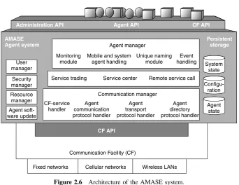
Administration API Agent API CF API CF API AMASE Agent system Persistent storage Agent manager Communication manager Monitoring module User manager
Fixed networks Cellular networks Wireless LANs Communication Facility (CF)
Security manager Resource manager Agent soft-ware update System state Configu-ration Agent state Mobile and system
agent handling
Unique naming module
Event handling
Service trading Service center Remote service call
CF-service handler Agent communication protocol handler Agent transport protocol handler Agent directory protocol handler
Figure 2.6 Architecture of the AMASE system.
facilities provide access to a broad range of underlying networks and handle the roaming between different kinds of networks.
The AS layer provides a runtime environment for cooperative MAs. This layer allows agents to migrate from one AS to another, to access services available in the network, and to communicate with other agents. The Service Center of the Agent System is a fundamental component for mobile agent management and user mobility and is used for locating and accessing services and agents.
The AMASE system and its supported agents are developed in Java. An agent system launcher supports loading a scaled version of the AS into a mobile device and executing it on different Java Virtual Machines (JVM). The launcher closely cooperates with a unit for agent system software update allowing for upgrading the AS’s software at least at start-up or upon request. An agent launcher is used for application allowing for more convenient and browser-like launching of agent-based applications by hiding all the Java and agent system specifics.
The Persistent Storage area is either located in the persistent memory area of the underlying device, or on a magnetic medium. This area is needed to save agents and the agent system state and configuration.
The CM comprises user and security managers that establish a user management and allow for the enforcement of access policies. An additional resource manager provides information about device utilization, for example, memory or agent population. A com-ponent for dynamic updates of the agents’ software allows for versioning and updates of agent classes.
The AM is responsible for controlling the agent population of the agent system. AM allows for launching and termination of agents and provides them with the functionality needed for migration, communication, service access, and so on. In AMASE environment, there are MAs and system agents. MAs are created by application and they can roam within the network. They are not allowed to access system resources for security reasons. Usually these agents interact with the user for an initial configuration before they are launched into the network. They allow the user to perform remote operations without a constant network connection.
MAs and system agents are supported by the AS. System agents can access system resources and become a mediator between the MAs and the system resources and the services they need to access.
The AM cooperates with the user manager and the resource manager, which permits them to assign detailed access rights to agents. Both agent types are maintained separately by the AM, which supports a clearly defined type-dependent handling, for example, in case of a shutdown. Agents are registered with the local AM, and MAs are also automatically registered with the Service Center’s AD.
In Figure 2.6, the CM connects the entire agent system to the communication facilities, which connect a device to the available networks. The CM surveys preconfigured ports on sockets provided by the communication facilities to receive incoming messages. Agents can be dispatched and handled by the AM. Each CM has access either to a local or remote router provided by the agent-related directories. This router helps CM to find and address the other agent systems. The CM is responsible for converting Java objects into byte streams and is involved in synchronous communication, which requires temporal suspension of agents.
CM and communication facilities optimize communication and connection handling. The protocols consider network and device characteristics, and Quality of Service (QoS) information. Connections are physically closed during timeouts but kept open virtually. These operations that are transparent to the agents save connection costs and support disconnected operations and user mobility. The following communications mechanisms are provided by using the agent system communication manager, its protocol handlers, and the underlying communication facilities:
• asynchronous one-way agent-to-agent messages;
• blackboards for local agent communication within agent systems – a blackboard is a data area where agents can leave information that may be read and removed by other agents under configurable access restrictions;
• postbox messages for specified agents; this is a message queue that belongs to a single agent and which is located at a well-known location in the network that is known to both the message senders and the postbox owner; the owner agent can only read the box contents and remove the messages, and all other agents can drop messages.
MAs are capable of migrating, which can occur at any time; thus, a mechanism is needed to determine an agent’s current location. This mechanism is not necessary for asynchronous communication and communication based on blackboards and postboxes; it is inevitable for direct communication of agents. The Mobile Agent System Interoperabil-ity FacilInteroperabil-ity (MASIF) specifies a Mobile Agent FacilInteroperabil-ity (MAF) component MAFFinder, which is an abstract facility for mobile agent localization. MAFFinder is abstract because it does not specify how the agents are to be localized – only that a presence of such facility is required. Concepts for mobile agent localization include broadcast, forwarding, and directory service/home registry.
AMASE system introduces a Service Center based on a directory service using general mobile agent execution cycle. MAs are restricted in their size and complexity owing to the costs of agent migration. MAs use services to execute the tasks required. The agents contact a facility in the agent system that provides a naming or trading service and passes information on the location of the requested services. This Service Center in AMASE system is based on the concept introduced by the Java Agent Environment (JAE).
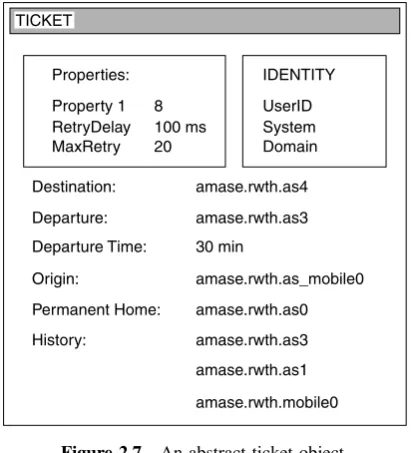
AMASE system introduces a ticket concept to pass information to MAs while keeping the actual migration and location information transparent. Mobile agent requesting a service from the Service Center receives a ticket shown in Figure 2.7. By calling useSer-vice (ticket), the MA uses the seruseSer-vice provided, migrating to the respective agent system if it is not located in the same agent system. In addition to the information about home loca-tion, destinaloca-tion, and migration history, it is possible to store additional data in the ticket object, for instance, departure time, maximum number of connection retries, and priority information. The origin entry provides details about the creation and the starting point of the MA that is needed if the agent returns after having accomplished its task. Because of the user mobility and the disconnected operations, the originating device might be turned off and may become unreachable for the mobile agent. In this case, the permanent home entry gives an alternative address. The permanent home is an agent system at the service provider or the agent enabled home computer.
The architecture of the Service Center shown in Figure 2.8 introduces a new mechanism for localizing MAs by using the AD. Whenever a MA requests a new service or migrates to another host, its position is updated in the Service Center. The agent location is stored in the AD. This is implemented as a Lightweight Directory Access Protocol (LDAP) server, with the Service Center holding an LDAP client for accessing the AD.
Destination:
Departure:
Departure Time:
Origin:
Permanent Home:
History:
amase.rwth.as4
amase.rwth.as3
30 min
amase.rwth.as_mobile0
amase.rwth.as0
amase.rwth.as3
amase.rwth.as1
amase.rwth.mobile0
Properties: IDENTITY
Property 1 UserID
RetryDelay System
MaxRetry 8 100 ms
20 Domain
TICKET
Figure 2.7 An abstract ticket object.
LDAP AD
Other service centers LDAP
client Trader
Service center
SC management
and remote service
call Local
services
Mobile agents
SC − API
Figure 2.8 Architecture of the service center.
There are no message bursts caused by agent localization. The AD concept allows a seam-less integration into the facilities required for localization services for mobile agent use.
AD. A user profile contains information about the user’s preferences and data, display and security settings, and scheduling information and address books. The profile directory is a generic database for maintaining user information, which includes application-specific data. Customized agents adapted to application-specific needs can be created on the device the user is currently deploying. The user can specify types of services to be used without having to be aware of their location or current availability.
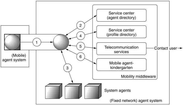
The mobility middleware system is presented in Figure 2.9. The mobile agent, equipped with the service description and a specification of the preferred mechanism to return results, contacts the AD to localize the appropriate system agents that provide the required services. The agent obtains the ticket and migrates to the appropriate system agents and uses their services. Once the results are generated, the profile directory is used. If the user specified a type of terminal to deliver the results, the MA obtains the address from the profile directory and returns the resultsviathe respective telecommunication service. On the other hand, if the user does not specify a method for returning the results, the MA decides which method to use. User and terminal profiles used with MAT create a flexible and device-independent user mobility.
The users can become temporarily unreachable when the results are available. MAs allow the users to disconnect after specifying the service. If the method specified for returning the result is an asynchronous message (e.g., e-mail, fax), no feedback is required by the MAs. On the other hand, if the agent’s execution depends on the user’s feedback or if the return method is selected by the user after an initial notification, the MA can-not be terminated and must wait for user input to continue execution. The AMASE system introduces the kindergarten concept for an MA, which recognized that the tar-get user is currently unavailable, or, if the execution of the notification method failed
Service center (agent directory)
Service center (profile directory)
Telecommunication services
Mobile agent-kindergarten
Mobility middleware
(Fixed network) agent system System agents
Contact user
(Mobile) agent system
3 6 5 4 2
1
2
Storage
Coordinator
Persistent storage
Mobile agent kindergarten 1
Figure 2.10 The mobile agent kindergarten concept.
or timed out, to contact a kindergarten coordinator that checks if the system having last served the MA is capable of holding this agent until the user becomes available. In this case, the agent is suspended until further notice. The agent is instructed to migrate to a host providing a kindergarten storage. This server suspends the MA and resumes it when the user reconnects. The MA can also be moved to persistent stor-age until being resumed, which allows for managing a large number of MAs. The kindergarten concept shown in Figure 2.10 provides a mechanism for handling MAs belonging to disconnected users and forms the basis of mobility support deploying user and terminal profiles.
2.3 MOBILE AGENT-BASED SERVICE
CONFIGURATION
MAT allows for object migration and supports Virtual Home Environment (VHE) in the Universal Mobile Telecommunications System (UMTS). VHE uses MAs in service subscription and configuration.
UMTS supports QoS, the Personal Communication Support (PCS), and VHE. The VHE allows for service mobility and roaming for the user, which carries subscribed and customized services while roaming. During the registration procedure, the VHE enables the visited network to obtain the information about the user’s service provider, the user’s personalized service profile, and the identification about service capabilities to execute specific services.
Provider systems End
systems
Applications (subscribed services)
Virtual home environment
Transport networks
Figure 2.11 Virtual home environment.
mobility. The enhancements of service control intelligence during service execution and dynamic subscription of a new third-party services should be allowed in the system.
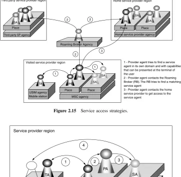
The UMTS environment shown in Figure 2.12 consists of a terminal, the AN, the SC & MMP, and the third-party service provider. A user registers at the terminal that presents services to the user. The user’s identification and authentication is handled by the UMTS Subscriber Identity Module (USIM). The network access of the terminal is managed by the access network. Fixed or mobile terminals are linked by the AN to the SC & MMP. The SC & MMP contains service logic and is responsible for the mobility management. Third-party service provides support supplementary services. A third-party service provider has a connection to one or more SC & MMPs and does not have its own mobility management facilities.
A middleware layer is introduced in UMTS architecture in Figure 2.13. The middleware consists of Distributed Agent Environment (DAE), for example, Grasshopper, which is built on the top of DPE, for example, CORBA, and spans all potential end user systems and provider systems. The nodes provide agent environments through middleware system
SC&MMP
SC&MMP
AN AN
Mobile station USIM
SC&MMP
Third party SP
Third party SP
Third party SP
End user system Home provider system Other provider system Third party provider system
AN Mobile station
USIM
Visited MSC Gateway MSC Third party service provider Agency
Agency Agency
Agents
DPE/DAE
Core network Agency
Figure 2.13 The distributed agent environment spanning across UMTS end user and provider systems.
to enable downloading and migration of MAs. MAs contain intelligence related to mobility management and service control (VHE control) and the end user application between the involved system nodes, including the Mobile Stations (MSs).
In agent-based UMTS, a VHE-agent realizes the VHE concept; a Service Agent (SA) represents a provided service; a Terminal Agent (TA) allows the terminal to inform the provider system about its capabilities; and a Provider Agent (PA) realizes a trader within the provider system, which manages all supported services (SA), that is, maintains an overview of all available services within the provider domain.
The VHE allows individually subscribed and customized services to follow their associ-ated users wherever they roam. The VHE-agent follows the user to the domain to which the user is roaming. At every domain, the VHE-agent provides the user’s subscribed services and configurations.
Agencies in the MS allow dynamic distribution of mobility management and service control intelligence to be downloaded dynamically from the MS into the (visited) provider system and from the (visited) provider system onto the MS, to be distributed within one provider system at the most appropriate location and to be distributed between different provider systems. The end systems through the USIM can take an active part in mobility management and service control.
The PA residing in every provider domain contains the knowledge of all services provided by this domain. The PA is designed as a trader in MASIF. The PA is the initial contact point of the VHE-agent after the user is roamed to a new domain. The PA is designated as a stationary agent since its task makes the migration of this agent not necessary.
USIM agency
Service agents
Service provider agency
Third party service agents
Converter agents SA
SA SA
PA VHE
TA
Outgoing (access)
Incoming
Figure 2.14 Basic agent relationships.
present the service such as reading out a fax or e-mail on a telephone. The knowledge of the terminal capabilities is maintained by the TA. Different types of agents and their communication relation