C
H A P T E R1
T
HE
O
RIGINS OF
F
IBER
O
PTIC
C
OMMUNICATIONS
J E F F H E C H T
Optical communication systems date back two centuries, to the “optical tele-graph” invented by French engineer Claude Chappe in the 1790s. His system was a series of semaphores mounted on towers, where human operators relayed mes-sages from one tower to the next. It beat hand-carried mesmes-sages hands down, but by the mid-19th century it was replaced by the electric telegraph, leaving a scat-tering of “telegraph hills” as its most visible legacy.
Alexander Graham Bell patented an optical telephone system, which he called the Photophone, in 1880, but his earlier invention, the telephone, proved far more practical. He dreamed of sending signals through the air, but the atmosphere did not transmit light as reliably as wires carried electricity. In the decades that followed, light was used for a few special applications, such as sig-naling between ships, but otherwise optical communications, such as the experi-mental Photophone Bell donated to the Smithsonian Institution, languished on the shelf.
1
In the intervening years, a new technology that would ultimately solve the problem of optical transmission slowly took root, although it was a long time before it was adapted for communications. This technology depended on the phe-nomenon of total internal reflection, which can confine light in a material sur-rounded by other materials with lower refractive index, such as glass in air.
In the 1840s, Swiss physicist Daniel Collodon and French physicist Jacques Babinet showed that light could be guided along jets of water for fountain dis-plays. British physicist John Tyndall popularized light guiding in a demonstration he first used in 1854, guiding light in a jet of water flowing from a tank. By the turn of the century, inventors realized that bent quartz rods could carry light and patented them as dental illuminators. By the 1940s, many doctors used illumi-nated Plexiglas tongue depressors.
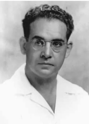
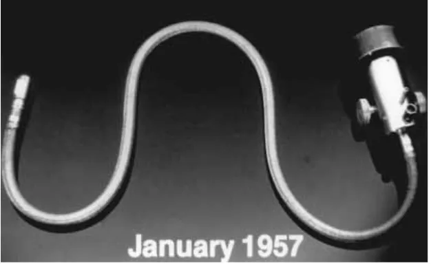
Optical fibers went a step further. They are essentially transparent rods of glass or plastic stretched to be long and flexible. During the 1920s, John Logie Baird in England and Clarence W. Hansell in the United States patented the idea of using arrays of hollow pipes or transparent rods to transmit images for televi-sion or facsimile systems. However, the first person known to have demonstrated image transmission through a bundle of optical fibers was Heinrich Lamm (Fig-ure 1-1), then a medical student in Munich. His goal was to look inside inaccessi-2 CHAPTER 1 — THE ORIGINS OF FIBER OPTIC COMMUNICATIONS
ble parts of the body, and in a 1930 paper he reported transmitting the image of a light bulb filament through a short bundle. However, the unclad fibers trans-mitted images poorly, and the rise of the Nazis forced Lamm, a Jew, to move to America and abandon his dreams of becoming a professor of medicine.
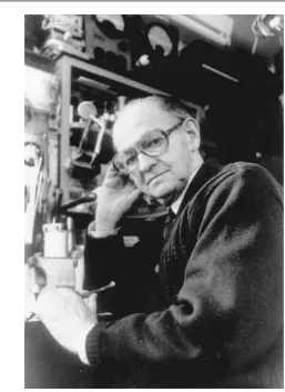
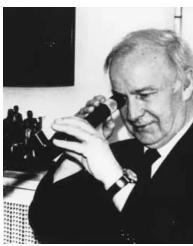
In 1951, Holger Møller Hansen (Figure 1-2) applied for a Danish patent on fiber optic imaging. However, the Danish patent office denied his application, cit-ing the Baird and Hansell patents, and Møller Hansen was unable to interest companies in his invention. Nothing more was reported on fiber bundles until 1954, when Abraham van Heel (Figure 1-3), of the Technical University of Delft CHAPTER 1 — THE ORIGINS OF FIBER OPTIC COMMUNICATIONS 3
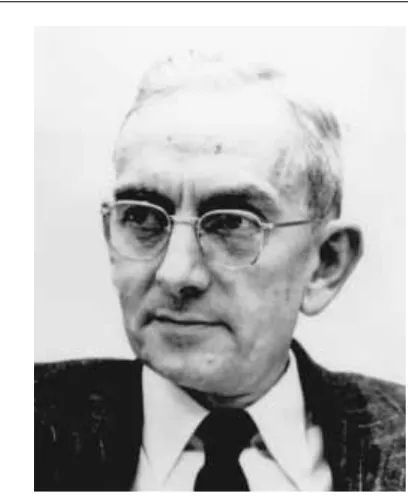
in Holland, and Harold H. Hopkins (Figure 1-4) and Narinder Kapany, of Impe-rial College in London, separately announced imaging bundles in the prestigious British journal Nature.
Neither van Heel nor Hopkins and Kapany made bundles that could carry light far, but their reports began the fiber optics revolution. The crucial innova-tion was made by van Heel, stimulated by a conversainnova-tion with the American opti-cal physicist Brian O’Brien (Figure 1-5). All earlier fibers were bare, with total internal reflection at a glass-air interface. Van Heel covered a bare fiber of glass or plastic with a transparent cladding of lower refractive index. This protected the total-reflection surface from contamination and greatly reduced crosstalk between fibers. The next key step was development of glass-clad fibers by Lawrence Curtiss (Figure 1-6), then an undergraduate at the University of Michi-gan working part-time on a project with physician Basil Hirschowitz (Figure 1-7) and physicist C. Wilbur Peters to develop an endoscope to examine the inside of the stomach (Figure 1-8). Will Hicks, then working at the American Optical Co., 4 CHAPTER 1 — THE ORIGINS OF FIBER OPTIC COMMUNICATIONS
Figure 1-3 Abraham C. S. van Heel, who made clad fibers at the Technical University of Delft. Courtesy H. J. Frankena, Faculty of Applied Physics, Technical University of Delft
made glass-clad fibers at about the same time, but his group lost a bitterly con-tested patent battle. By 1960, glass-clad fibers had attenuation of about one deci-bel per meter, fine for medical imaging, but much too high for communications. Meanwhile, telecommunications engineers were seeking more transmission bandwidth. Radio and microwave frequencies were in heavy use, so engineers looked to higher frequencies to carry the increased loads they expected with the growth of television and telephone traffic. Telephone companies thought video telephones lurked just around the corner and would escalate bandwidth demands even further. On the cutting edge of communications research were millimeter-wave systems, in which hollow pipes served as millimeter-waveguides to circumvent poor atmospheric transmission at tens of gigahertz, where wavelengths were in the millimeter range.
Even higher optical frequencies seemed a logical next step in 1958 to Alec Reeves, the forward-looking engineer at Britain’s Standard Telecommunications Laboratories, who invented digital pulse-code modulation before World War II. Other people climbed on the optical communications bandwagon when the laser CHAPTER 1 — THE ORIGINS OF FIBER OPTIC COMMUNICATIONS 5
6 CHAPTER 1 — THE ORIGINS OF FIBER OPTIC COMMUNICATIONS
CHAPTER 1 — THE ORIGINS OF FIBER OPTIC COMMUNICATIONS 7
Figure 1-7 Basil Hirschowitz about the time he helped to develop the first fiber optic endoscope. Courtesy Basil Hirschowitz
was invented in 1960. The July 22, 1960, issue of Electronics introduced its report on Theodore Maiman’s demonstration of the first laser by saying, “Usable communications channels in the electromagnetic spectrum may be extended by development of an experimental optical-frequency amplifier.”
Serious work on optical communications had to wait for the CW helium-neon laser. While air is far more transparent to light at optical wavelengths than to millimeter waves, researchers soon found that rain, haze, clouds, and atmos-pheric turbulence limited the reliability of long-distance atmosatmos-pheric laser links. By 1965, it was clear that major technical barriers remained for both millimeter-wave and laser telecommunications. Millimeter millimeter-waveguides had low loss, although only if they were kept precisely straight; developers thought the biggest problem was the lack of adequate repeaters. Optical waveguides were proving to be a problem. Stewart Miller’s group at Bell Telephone Laboratories was work-ing on a system of gas lenses to focus laser beams along hollow waveguides for long-distance telecommunications. However, most of the telecommunications industry thought the future belonged to millimeter waveguides.
Optical fibers had attracted some attention because they were analogous in theory to plastic dielectric waveguides used in certain microwave applications. In 1961, Elias Snitzer at American Optical, working with Hicks at Mosaic Fabrica-tions (now Galileo Electro-Optics), demonstrated the similarity by drawing fibers with cores so small they carried light in only one waveguide mode. However, vir-tually everyone considered fibers too lossy for communications; attenuation of a decibel per meter was fine for looking inside the body, but communications oper-ated over much longer distances and required loss of no more than 10 or 20 deci-bels per kilometer.
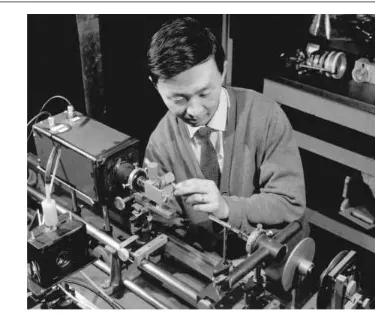
One small group did not dismiss fibers so easily—a team at Standard Telecommunications Laboratories (STL), initially headed by Antoni E. Kar-bowiak, that worked under Reeves to study optical waveguides for communica-tions. Karbowiak soon was joined by a young engineer born in Shanghai, Charles K. Kao (Figure 1-9).
Kao took a long, hard look at fiber attenuation. He collected samples from fiber makers, and carefully investigated the properties of bulk glasses. His research convinced him that the high losses of early fibers were due to impurities, not to silica glass itself. In the midst of this research, in December 1964, Kar-bowiak left STL to become chair of electrical engineering at the University of New South Wales in Australia, and Kao succeeded him as manager of optical communications research. With George Hockham (Figure 1-10), another young STL engineer who specialized in antenna theory, Kao worked out a proposal for long-distance communications over singlemode fibers. Convinced that fiber loss should be reducible below 20 decibels per kilometer, they presented a paper at a London meeting of the Institution of Electrical Engineers (IEE). The April 1, 1966, issue of Laser Focusnoted Kao’s proposal:
At the IEE meeting in London last month, Dr. C. K. Kao observed that short-distance runs have shown that the experimental optical waveguide developed by Standard Telecommunications Laboratories has an infor-mation-carrying capacity . . . of one gigacycle, or equivalent to about 200 tv channels or more than 200,000 telephone channels. He described STL’s device as consisting of a glass core about three or four microns in diameter, clad with a coaxial layer of another glass having a refractive index about one percent smaller than that of the core. Total diameter of the waveguide is between 300 and 400 microns. Surface optical waves are propagated along the interface between the two types of glass.
According to Dr. Kao, the fiber is relatively strong and can be easily supported. Also, the guidance surface is protected from external influ-ences. . . . the waveguide has a mechanical bending radius low enough to
CHAPTER 1 — THE ORIGINS OF FIBER OPTIC COMMUNICATIONS 9
make the fiber almost completely flexible. Despite the fact that the best readily available low-loss material has a loss of about 1000 dB/km, STL believes that materials having losses of only tens of decibels per kilome-ter will eventually be developed.
Kao and Hockham’s detailed analysis was published in the July 1966, Pro-ceedings of the Institution of Electrical Engineers. Their daring forecast that fiber loss could be reduced below 20 dB/km attracted the interest of the British Post Office, which then operated the British telephone network. F.F. Roberts, an engi-neering manager at the Post Office Research Laboratory (then at Dollis Hill in London), saw the possibilities and persuaded others at the Post Office. His boss, Jack Tillman, tapped a new research fund of 12 million pounds to study ways to decrease fiber loss.
With Kao almost evangelically promoting the prospects of fiber communica-tions, and the Post Office interested in applicacommunica-tions, laboratories around the world began trying to reduce fiber loss. It took four years to reach Kao’s goal of 20 dB/km, and the route to success proved different than many had expected. Most groups tried to purify the compound glasses used for standard optics, which are easy to melt and draw into fibers. At the Corning Glass Works (now 10 CHAPTER 1 — THE ORIGINS OF FIBER OPTIC COMMUNICATIONS
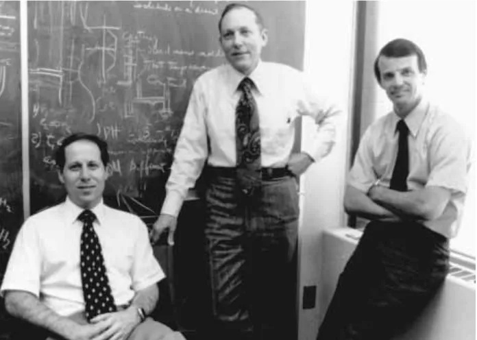
Corning, Inc.), Robert Maurer, Donald Keck, and Peter Schultz (Figure 1-11) started with fused silica, a material that can be made extremely pure, but has a high melting point and a low refractive index. They made cylindrical preforms by depositing purified materials from the vapor phase, adding carefully controlled levels of dopants to make the refractive index of the core slightly higher than that of the cladding, without raising attenuation dramatically. In September 1970, they announced they had made singlemode fibers with attenuation at the 633-nanometer (nm) helium neon line below 20 dB/km. The fibers were fragile, but tests at the new British Post Office Research Laboratories facility in Martlesham Heath confirmed the low loss.
The Corning breakthrough was among the most dramatic of many develop-ments that opened the door to fiber optic communications. In the same year, Bell Labs and a team at the Loffe Physical Institute in Leningrad (now St. Petersburg) made the first semiconductor diode lasers able to emit carrier waves (CW) at room temperature. Over the next several years, fiber losses dropped dramatically, aided both by improved fabrication methods and by the shift to longer wave-lengths where fibers have inherently lower attenuation.
CHAPTER 1 — THE ORIGINS OF FIBER OPTIC COMMUNICATIONS 11
Early singlemode fibers had cores several micrometers in diameter and in the early 1970s that bothered developers. They doubted it would be possible to achieve the micrometer-scale tolerances needed to couple light efficiently into the tiny cores from light sources or in splices or connectors. Not satisfied with the low bandwidth of step-index multimode fiber, they concentrated on multimode fibers with a refractive-index gradient between core and cladding, and core diam-eters of 50 or 62.5 micromdiam-eters. The first generation of telephone field trials in 1977 used such fibers to transmit light at 850 nm from gallium-aluminum-arsenide laser diodes.
Those first-generation systems could transmit light several kilometers with-out repeaters, but were limited by loss of abwith-out 2 dB/km in the fiber. A second generation soon appeared, using new indium gallium arsenide phosphide (InGaAsP) lasers that emitted at 1.3 micrometers, where fiber attenuation was as low as 0.5 dB/km, and pulse dispersion was somewhat lower than at 850 nm. Development of hardware for the first transatlantic fiber cable showed that sin-glemode systems were feasible, so when deregulation opened the long-distance phone market in the early 1980s, the carriers built national backbone systems of singlemode fiber with 1300-nm sources. That technology has spread into other telecom applications and remains the standard for most fiber systems.
However, a new generation of singlemode systems is now beginning to find applications in submarine cables and systems serving large numbers of sub-scribers. They operate at 1.55 micrometers, where fiber loss is 0.2 to 0.3 dB/km, allowing even longer repeater spacings. More important, erbium-doped optical fibers can serve as optical amplifiers at that wavelength, avoiding the need for electro-optic regenerators. Submarine cables with optical amplifiers can operate at speeds to 5 gigabits per second and can be upgraded from lower speeds simply by changing terminal electronics. Optical amplifiers also are attractive for fiber systems delivering the same signals to many terminals, because the fiber ampli-fiers can compensate for losses in dividing the signals among many terminals.
The biggest challenge remaining for fiber optics is economic. Today tele-phone and cable television companies can cost justify installing fiber links to remote sites serving tens to a few hundreds of customers. However, terminal equipment remains too expensive to justify installing fibers all the way to homes, at least for present services. Instead, cable and phone companies run twisted wire pairs or coaxial cables from optical network units to individual homes. Time will see how long that lasts.
REVIEW QUESTIONS
1. Confining light in a material by surrounding it by another material with lower refractive index is the phenomenon of _____________
a. cladding.
b. total internal reflection. c. total internal refraction. d. transmission.
2. Abraham van Heel, in order to increase the total internal reflection, cov-ered bare fiber with transparent cladding of _____________
a. higher refractive index. b. lower refractive index.
c. higher numerical aperture. d. lower numerical aperture.
3. The high loss of early optical fiber was mainly due to _____________ a. impurities.
b. silica. c. wave guides. d. small cores.
4. _____________, using fused silica, made the first low loss (<20 dB/Km) singlemode optical fiber.
a. Standard Telecommunications Laboratory b. The Post Office Research Laboratory
c. Corning Glass Works d. Dr. Charles K. Kao
5. Erbium-doped optical fiber can serve as _____________ a. cladding.
b. a pulse suppresor. c. a regenerator. d. an amplifier.
C
H A P T E R2
B
ASICS OF
F
IBER
O
PTICS
E L I A S A. A W A D
INTRODUCTION
Optical fiber is the medium in which communication signals are transmitted from one location to another in the form of light guided through thin fibers of glass or plastic. These signals are digital pulses or continuously modulated analog streams of light representing information. These can be voice information, data informa-tion, computer informainforma-tion, video informainforma-tion, or any other type of information. These same types of information can be sent on metallic wires such as twisted pair and coax and through the air on microwave frequencies. The reason to use optical fiber is because it offers advantages not available in any metallic conduc-tor or microwaves.
The main advantage of optical fiber is that it can transport more information longer distances in less time than any other communications medium. In addition, it is unaffected by the interference of electromagnetic radiation, making it possible to transmit information and data with less noise and less error. There are also many other applications for optical fiber that are simply not possible with metal-lic conductors. These include sensors/scientific appmetal-lications, medical/surgical applications, industrial applications, subject illumination, and image transport.
Most optical fibers are made of glass, although some are made of plastic. For mechanical protection, optical fiber is housed inside cables. There are many types
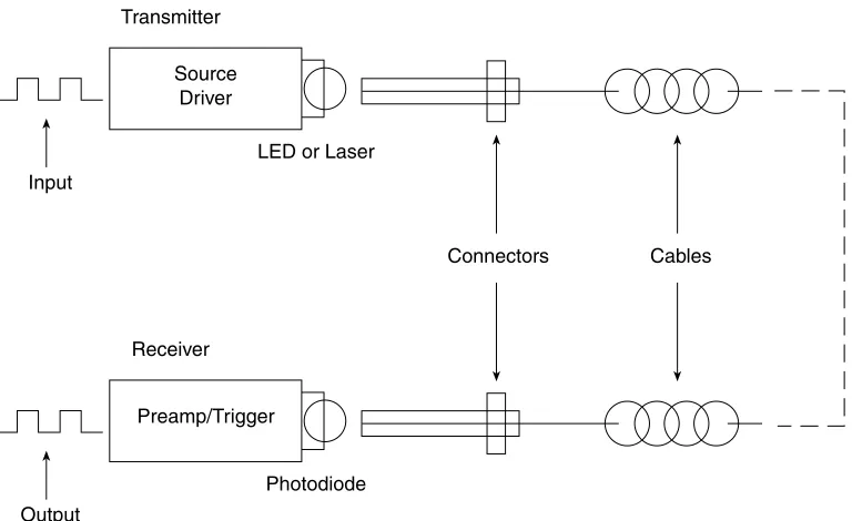
Figure 2-1 A typical fiber optic data link.
and configurations of cables, each for a specific application: indoor, outdoor, in the ground, underwater, deep ocean, overhead, and others.
An optical fiber data link is made up of three elements (Figure 2-1):
1. A light source at one end (laser or light-emitting diode [LED]), including a connector or other alignment mechanism to connect to the fiber. The light source will receive its signal from the support electronics to convert the electrical information to optical information.
2. The fiber (and its cable, connectors, or splices) from point to point. The fiber transports this light to its destination.
3. The light detector on the other end with a connector interface to the fiber. The detector converts the incoming light back to an electrical sig-nal, producing a copy of the original electrical input. The support elec-tronics will process that signal to perform its intended communications function.
The source and detector with their necessary support electronics are called the transmitter and receiver, respectively.
16 CHAPTER 2 — BASICS OF FIBER OPTICS
Transmitter Source
Driver
Input
LED or Laser
Receiver
Output
Photodiode Preamp/Trigger
Figure 2-3 Optical fiber construction.
Figure 2-2 Long distance data links require repeaters to regenerate signals.
In long-distance systems (Figure 2-2) the use of intermediate amplifiers may be necessary to compensate for the signal loss over the long run of the fiber. Therefore, long-distance networks will be comprised of a number of identical links connected together. Each repeater consists of a receiver, transmitter, and support electronics.
OPTICAL FIBER
Optical fiber (Figure 2-3) is comprised of a light-carrying core surrounded by a cladding that traps the light in the core by the principle of total internal reflec-tion. By making the core of the fiber of a material with a higher refractive index, we can cause the light in the core to be totally reflected at the boundary of the cladding for all light that strikes at greater than a critical angle. The critical angle is determined by the difference in the composition of the materials used in the core and cladding. Most optical fibers are made of glass, although some are made of plastic. The core and cladding are usually fused silica glass covered by a plas-tic coating, called the buffer, that protects the glass fiber from physical damage and moisture. Some all-plastic fibers are used for specific applications.
Glass optical fibers are the most common type used in communication appli-cations. Glass optical fibers can be singlemode or multimode. Most of today’s telecom and community antenna television (CATV) systems use singlemode fibers, whereas local area networks (LANs) use multimode graded-index fibers. CHAPTER 2 — BASICS OF FIBER OPTICS 17
Repeater Repeater Repeater Repeater Fiber Fiber Fiber
Core
Cladding
Multimode Step Index
Core
Cladding
Multimode Graded Index
Core
Cladding
Singlemode
Core
Cladding
Figure 2-4 The three types of optical fiber.
Singlemode fibers are smaller in core diameter than multimode fibers and offer much greater bandwidth, but the larger core size of multimode fiber makes cou-pling to low cost sources such as LEDs much easier. Multimode fibers may be of the step-index or graded-index design.
Plastic optical fibers are large core step-index multimode fibers, although graded-index plastic fiber is under development. Because plastic fibers have a large diameter and can be cut with simple tools, they are easy to work with and can use low-cost connectors. Plastic fiber is not used for long distance because it has high attenuation and lower bandwidth than glass fibers. However, plastic optical fiber may be useful in the short runs from the street to the home or office and within the home or office.
the numerical aperture (NA). Two types of multimode fiber exist, distinguished by the index profile of their cores and how light travels in them (Table 2-1).
Step-index multimode fiber has a core composed completely of one type of glass. Light travels in straight lines in the fiber, reflecting off the core/cladding interface. The NA is determined by the difference in the indices of refraction of the core and cladding and can be calculated by Snell’s law. Since each mode or angle of light travels a different path, a pulse of light is dispersed while traveling through the fiber, limiting the bandwidth of step-index fiber.
In graded-index multimode fiber, the core is composed of many different lay-ers of glass, chosen with indices of refraction to produce an index profile approx-imating a parabola, where from the center of the core the index of refraction gets lower toward the cladding. Since light travels faster in the lower index of refrac-tion glass, the light will travel faster as it approaches the outside of the core. Like-wise, the light traveling closest to the core center will travel the slowest. A properly constructed index profile will compensate for the different path lengths of each mode, increasing the bandwidth capacity of the fiber by as much as 100 times over that of step-index fiber.
Singlemode fiber just shrinks the core size to a dimension about six times the wavelength of light traveling in the fiber and it has a smaller difference in the refractive index of the core and cladding, causing all the light to travel in only one mode. Thus modal dispersion disappears and the bandwidth of the fiber increases tremendously over graded-index fiber.
FIBER MANUFACTURE
Three methods are used today to fabricate moderate-to-low loss waveguide fibers: modified chemical vapor deposition (MCVD), outside vapor deposition (OVD), and vapor axial deposition (VAD).
CHAPTER 2 — BASICS OF FIBER OPTICS 19
Table 2-1 Fiber Types and Typical Specifications
Core/Cladding Attenuation Coefficient (dBkm) Bandwidth Fiber Type Diameter(m) 850 nm 1300 nm 1550 nm (MHz-km)
Multimode/Plastic 1 mm (1 dB/m @665 nm) Low
Multimode/Step Index 200/240 6 50 @ 850 nm
Multimode/Graded Index 50/125 3 1 600 @1300 nm
62.5/125 3 1 500 @1300 nm
85/125 3 1 500 @1300 nm
100/140 3 1 300 @1300 nm
Figure 2-5 Modified chemical vapor deposition (MCVD).
Modified Chemical Vapor Deposition (MCVD)
In MCVD a hollow glass tube, approximately 3 feet long and 1 inch in diameter (1 m long by 2.5 cm diameter), is placed in a horizontal or vertical lathe and spun rapidly. A computer-controlled mixture of gases is passed through the inside of the tube. On the outside of the tube, a heat source (oxygen/hydrogen torch) passes up and down as illustrated in Figure 2-5.
Each pass of the heat source fuses a small amount of the precipitated gas mixture to the surface of the tube. Most of the gas is vaporized silicon dioxide (glass), but there are carefully controlled remounts of impurities (dopants) that cause changes in the index of refraction of the glass. As the torch moves and the preform spins, a layer of glass is formed inside the hollow preform. The dopant (mixture of gases) can be changed for each layer so that the index may be varied across the diameter.
After sufficient layers are built up, the tube is collapsed into a solid glass rod referred to as a preform. It is now a scale model of the desired fiber, but much shorter and thicker. The preform is then taken to the drawing tower, where it is pulled into a length of fiber up to 10 kilometers long.
Outside Vapor Deposition (OVD)
The OVD method utilizes a glass target rod that is placed in a chamber and spun rapidly on a lathe. A computer-controlled mixture of gases is then passed between the target rod and the heat source as illustrated in Figure 2-6. On each pass of the heat source, a small amount of the gas reacts and fuses to the outer surface of the rod. After enough layers are built up, the target rod is removed and the remaining soot preform is collapsed into a solid rod. The preform is then taken to the tower and pulled into fiber.
20 CHAPTER 2 — BASICS OF FIBER OPTICS
Figure 2-6 Outside vapor deposition (OVD).
Figure 2-7 Vapor axial deposition (VAD). Vapor Axial Deposition (VAD)
The VAD process utilizes a very short glass target rod suspended by one end. A computer-controlled mixture of gases is applied between the end of the rod and the heat source as shown in Figure 2-7. The heat source is slowly backed off as the preform lengthens due to tile soot buildup caused by gases reacting to the heat and fusing to the end of the rod. After sufficient length is formed, the target rod is removed from the end, leaving the soot preform. The preform is then taken to the drawing tower to be heated and pulled into the required fiber length.
CHAPTER 2 — BASICS OF FIBER OPTICS 21
Rotating
Flame Gases
Soot Preform
Heat Source Moving Back and Forth
Target Rod
Gases
Target Rod
Soot Preform
Figure 2-8 Drawing the fiber from the preform and coating the fiber. Coating the Fiber for Protection
After the fiber is pulled from the preform, a protective coating is applied very quickly after the formation of the hair-thin fiber (Figure 2-8). The coating is nec-essary to provide mechanical protection and prevent the ingress of water into any fiber surface cracks. The coating typically is made up of two parts, a soft inner coating and a harder outer coating. The overall thickness of the coating varies between 62.5 and 187.5 µm, depending on fiber applications.
22 CHAPTER 2 — BASICS OF FIBER OPTICS
Moveable Blank Holder
Furnace
Fiber Drawing
Diameter Monitor
Coating Applicator
Ultraviolet Lamps
CHAPTER 2 — BASICS OF FIBER OPTICS 23
Figure 2-9 Total internal reflection in an optical fiber.
Critical angle
These coatings are typically strippable by mechanical means and must be removed before fibers can be spliced or connectorized.
ADVANCED STUDY
What Is the Index of Refraction?
The index of refraction of a material is the ratio of the speed of light in vac-uum to that in the material. In other words, the index of refraction is a measure of how much the speed of light slows down after it enters the material. Since light has its highest speed in vacuum, and since light slows down whenever it enters any medium (water, plastic, glass, crystal, oil, etc.), the index of refraction of all media is greater than one. For exam-ple, the index of refraction in a vacuum is 1, that of glass and plastic opti-cal fibers is approximately 1.5, and water has an index of refraction of approximately 1.3
When light goes from one material to another of a different index of refraction, its path will bend, causing an illusion similar to the “bent” stick stuck into water. At its limits, this phenomenon is used to reflect the light at the core/cladding boundary of the fiber and trap it in the core (Figure 2-9). By choosing the material differences between the core and cladding, one can select the angle of light at which this light trapping, called total internal reflection, occurs. This angle defines a primary fiber specification, the numerical aperture.
FIBER APPLICATIONS
radiation is a concern, since it can be made with a pure silica core that is not read-ily affected by radiation.
Graded-index multimode fiber is used for data communications systems where the transmitter sources are LEDs. While four graded-index multimode fibers have been used over the history of fiber optic communications, one fiber now is by far the most widely used by virtually all multimode datacom networks—62.5/125 µm.
The telephone companies use singlemode fiber for its better performance at higher bit rates and its lower loss, allowing faster and longer unrepeated links for long-distance telecommunications. It is also used in CATV, since today’s analog CATV networks use laser sources designed for singlemode fiber and future CATV networks will use compressed digital video signals. Almost all other high-speed networks are using singlemode fiber, either to support gigabit data rates or long-distance links.
FIBER PERFORMANCE
Purity of the medium is very important for best transmission of an optical signal inside the fiber. Perfect vacuum is the purest medium we can have in which to transmit light. Since all optical fibers are made of solid, not hollow, cores, we have to settle for second best in terms of purity. Technology makes it possible for us to make glass very pure, however.
Impurities are the unwanted things that can get into the fiber and become a part of its structure. Dirt and impurities are two different things. Dirt comes to the fiber from dirty hands and a dirty work environment. This can be cleaned off with alcohol wipes. Impurities, on the other hand, are built into the fiber at the time of manufacture; they cannot be cleaned off. These impurities will cause parts of optical signal to be lost due to scattering or absorption causing attenuation of the signal. If we have too many impurities in the fiber, too much of the optical signal will be lost and what is left over at the output of the fiber will not be enough for reliable communications.
Much of the early research and development of optical fiber centered on methods to make the fiber purity higher to reduce optical losses. Today’s fibers are so pure that as a point of comparison, if water in the ocean was as pure, we would be able to see the bottom on a sunny day.
Optical glass fiber has another layer (or two) that surrounds the cladding, known as the buffer. The buffer is a plastic coating(s) that provides scratch pro-tection for the glass below. It also adds to the mechanical strength of the fiber and protects it from moisture damage. On straight pulling (tension), glass optical fiber is five times stronger than some steel. But when it comes to twisting and bending, glass must not be stressed beyond its limits or it will fracture.
Figure 2-10 Fiber loss mechanisms. Fiber Attenuation
The attenuation of the optical fiber is a result of two factors—absorption and scattering (Figure 2-10). Absorption is caused by the absorption of the light and conversion to heat by molecules in the glass. Primary absorbers are residual OH+ and dopants used to modify the refractive index of the glass. This absorption occurs at discrete wavelengths, determined by the elements absorbing the light. The OH+absorption is predominant, and occurs most strongly around 1000 nm, 1400 nm, and above 1600 nm.
The largest cause of attenuation is scattering. Scattering occurs when light collides with individual atoms in the glass and is anisotrophic. Light that is scat-tered at angles outside the critical angle of the fiber will be absorbed into the cladding or scattered in all directions, even transmitted back toward the source. Scattering is also a function of wavelength, proportional to the inverse fourth power of the wavelength of the light. Thus, if you double the wavelength of the light, you reduce the scattering losses by 24 or 16 times. Therefore, for long-distance transmission, it is advantageous to use the longest practical wavelength for minimal attenuation and maximum distance between repeaters. Together, absorption and scattering produce the attenuation curve for a typical glass opti-cal fiber shown in Figure 2-10.
Fiber optic systems transmit in the windows created between the absorption bands at 850 nm, 1300 nm, and 1550 nm, where physics also allows one to fab-ricate lasers and detectors easily. Plastic fiber has a more limited wavelength band that limits practical use to 660-nm LED sources.
CHAPTER 2 — BASICS OF FIBER OPTICS 25
Atten
uation
Scattering
Absorption
Figure 2-11 Modal dispersion, caused by different path lengths in the fiber, is corrected in graded-index fiber.
Fiber Bandwidth
Fiber’s information transmission capacity is limited by two separate components of dispersion: modal (Figure 2-11) and chromatic (Figure 2-12). Modal dispersion occurs in step-index multimode fiber where the paths of different modes are of varying lengths. Modal dispersion also comes from the fact that the index profile of graded-index multimode fiber is not perfect. The graded-index profile was chosen to theoretically allow all modes to have the same group velocity or transit speed along the length of the fiber. By making the outer parts of the core a lower index of refraction than the inner parts of the core, the higher order modes speed up as they go away from the center of the core, compensating for their longer path lengths. 26 CHAPTER 2 — BASICS OF FIBER OPTICS
Multimode Step Index
Core
Cladding
Multimode Graded Index
Core
Cladding
Figure 2-12 Chromatic dispersion occurs because light of different colors (wavelengths) travels at different speeds in the core of the fiber.
In an idealized graded-index fiber, all modes have the same group velocity and no modal dispersion occurs. But in real fibers, the index profile is a piecewise approximation and all modes are not perfectly transmitted, allowing some modal dispersion. Since the higher-order modes have greater deviations, the modal dis-persion of a fiber (and therefore its laser bandwidth) tends to be very sensitive to modal conditions in the fiber. Thus the bandwidth of longer fibers degrades non-linearly as the higher-order modes are attenuated more strongly.
The second factor in fiber bandwidth is chromatic dispersion. Remember, a prism spreads out the spectrum of incident light since the light travels at different speeds according to its color and is therefore refracted at different angles. The usual way of stating this is the index of refraction of the glass is wavelength dependent. Thus, a carefully manufactured graded-index multimode fiber can only be optimized for a single wavelength, usually near 1300 nm, and light of other colors will suffer from chromatic dispersion. Even light in the same mode will be dispersed if it is of different wavelengths.
Chromatic dispersion is a bigger problem with LEDs, which have broad spec-tral outputs, unlike lasers that concentrate most of their light in a narrow specspec-tral range. Chromatic dispersion occurs with LEDs because much of the power is away from the zero dispersion wavelength of the fiber. High-speed systems such as Fiber Distributed Data Interface (FDDI), based on broad output surface emit-ter LEDs, suffer such intense chromatic dispersion that transmission over only 2 kilometer of 62.5/125 fiber can be risky.
Modal Effects on Attenuation and Bandwidth
The way light travels in modes in multimode fiber can affect attenuation and bandwidth of the fiber. In order to model a network or test multimode fiber optic cables accurately and reproducibly, it is necessary to understand modal distribu-tion, mode control, and attenuation correction factors. Modal distribution in multimode fiber is important to measurement reproducibility and accuracy.
CHAPTER 2 — BASICS OF FIBER OPTICS 27
ADVANCED STUDY
What Is Modal Distribution?
28 CHAPTER 2 — BASICS OF FIBER OPTICS
back and forth from core/cladding boundaries as they are transmitted down the fiber. Since these higher-order modes travel a longer distance than the axial ray, they are responsible for the dispersion that limits the fiber’s bandwidth.
In graded-index fiber, the reduction of the index of refraction of the core as one approaches the cladding causes the higher-order modes to fol-low a curved path that is longer than the axial ray (the “zero-order mode”). However, by virtue of the lower index of refraction away from the axis, light speeds up as it approaches the cladding, thus taking approximately the same time to travel through the fiber. Therefore the “dispersion,” or varia-tions in transit time for various modes, is minimized and bandwidth of the fiber is maximized.
However, the fact that the higher-order modes travel farther in the glass core means that they have a greater likelihood of being scattered or absorbed, the two primary causes of attenuation in optical fibers. There-fore, the higher-order modes will have greater attenuation than lower-order modes, and a long length of fiber that was fully filled (all modes had the same power level launched into them) will have a lower amount of power in the higher-order modes than will a short length of the same fiber.
This change in modal distribution between long and short fibers can be described as a “transient loss,” and can make big differences in the measurements one makes with the fiber. It not only changes the modal distribution, it also changes the effective core diameter and apparent numerical aperture.
The term “equilibrium modal distribution” (EMD) is used to describe the modal distribution in a long fiber that has lost the higher-order modes. A “long” fiber is one in EMD, while a “short” fiber has all its initially launched higher-order modes.
In the laboratory, a critical optical system is used to fully fill the fiber modes and a “mode filter,” usually a mandrel wrap that stresses the fiber and increases loss for the higher-order modes, is used to simulate EMD conditions. A “mode scrambler,” made by fusion splicing a step-index fiber into the graded-index fiber near the source, can also be used to fill all modes equally.
Mode Conditioners
There are three basic “gadgets” used to condition the modal distribution in mul-timode fibers: mode strippers that remove unwanted cladding mode light, mode scramblers that mix modes to equalize power in all the modes, and mode filters that remove the higher-order modes to simulate EMD or steady-state conditions. These are discussed in Chapter 17.
REVIEW QUESTIONS
1. The main advantage(s) of optical is (are) its ability to ________________ than other communications media.
a. transport more information b. transport information faster c. transport information farther d. all of the above
2. A fiber optic data link is made up of three elements: 1. ________________
2. ________________ 3. ________________
3. Plastic optical fibers are ________________ fibers. a. singlemode
b. large core step-index c. large core graded-index d. either a or b
4. Optical fiber is comprised of three layers: 1. ________________
2. ________________ 3. ________________
5. What does 62.5 refer to when written 62.5/125? a. diameter of the core
b. diameter of the cladding c. numerical aperture d. index profile
6. In graded-index optical fiber, the index profile approximates a parabola. The benefit of this is ________________
a. reduced bandwidth. b. reduced cross-talk.
c. increased modal dispersion. d. reduced modal dispersion.
7. Three methods used to fabricate optical fiber: 1. ________________
2. ________________ 3. ________________
8. Match the following fibers to the application they are best suited for: ______ Graded-index multimode a. long-distance telecommunications ______ Step-index multimode b. data communications
______ Singlemode c. efficient source power coupling 9. The largest cause of attenuation is ________________
a. dopants. b. absorption.
c. moisture. d. scattering.
10. Optical fiber’s bandwidth, or information transmission capacity, is limited by two factors:
C
H A P T E R3
F
IBER
O
PTIC
N
ETWORKS
J I M H AY E S A N D P H I L S H E C K L E R
One often sees articles written about fiber optic communications networks that imply that fiber optics is “new.” That is hardly the case. The first fiber optic tele-phone network was installed in Chicago in 1976, and by 1979, commercial fiber optic computer datalinks were available. Since then, fiber has become common-place in the communications infrastructure.
If you make a long-distance call today, your voice is undoubtedly being transmitted on fiber optic cable, since it has replaced over 90 percent of all voice circuits for long-distance communications. Transoceanic links are being con-verted to fiber optics at a very high rate, since all new undersea cables are fiber optics. Phone company offices are being interconnected with fiber, and most large office buildings have fiber optic telephone connections into the buildings themselves. Only the last links to the home, office, and phone are not fiber.
CATV also uses fiber optics via a unique analog transmission scheme, but they are already planning on fiber moving to compressed digital video. Most large city CATV systems are being converted to fiber optics for reliability and in order to offer new services such as Internet connections and phone service. Only fiber offers the bandwidth necessary for carrying voice, data, and video simultaneously. The LAN backbone also has become predominately fiber-based. The back-end of mainframe computers is also primarily fiber. The desktop is the only hold-out, currently a battlefield between the copper and fiber contingents.
Figure 3-1 Telephone fiber optic architecture.
Security, building management, audio, process control, and almost any other system that requires communications cabling have become available on fiber optics. Fiber optics really is the medium of choice for all high bandwidth and/or long-distance communications. Let us look at why it is, how to evaluate the eco-nomics of copper versus fiber, and how to design fiber networks with the best availability of options for upgradeability in the future.
IT IS REALLY ALL A MATTER OF ECONOMICS
The use of fiber optics is entirely an issue of economics. Widespread use occurred when the cost declined to a point that fiber optics became less expensive than transmission over copper wires, radio, or satellite links. However, for each appli-cation, the turnover point has been reached for somewhat different reasons. Telephony
Fiber optics has become widely used in telephone systems because of its enor-mous bandwidth and distance advantages over copper wires. The application for fiber in telephony is simply connecting switches over fiber optic links (Figure 3-1). Commercial systems today carry more phone conversations over a single pair of fibers than could be carried over thousands of copper pairs. Material costs, 32 CHAPTER 3 — FIBER OPTIC NETWORKS
Long Distance
Local Loop (City)
Subscriber Loop
(Fiber to the Curb—FTTC)
installation, and splicing labor and reliability are all in fiber’s favor, not to men-tion space consideramen-tions. In major cities today, insufficient space exists in cur-rent conduit to provide communications needs over copper wire.
While fiber carries over 90 percent of all long-distance communications and 50 percent of local communications, the penetration of fiber to the curb (FTTC) and fiber to the home (FTTH) has been hindered by a lack of cost-effectiveness. These two final frontiers for fiber in the phone systems hinge on fiber becoming less expensive and customer demand for high bandwidth services that would be impossible over current copper telephone wires. Digital subscriber loop (DSL) technology has enhanced the capacity of the current copper wire home connec-tions so as to postpone implementation of FTTH for perhaps another decade.
Telecommunications led the change to fiber optic technology. The initial use of fiber optics was simply to build adapters that took input from traditional tele-phone equipment’s electrical signals on copper cables, multiplexed many signals to take advantage of the higher bit-rate capability of fiber, and used high-power laser sources to allow maximum transmission distances.
After many years of all these adapters using transmission protocols propri-etary to each vendor, Bellcore (now Telcordia) began working on a standard net-work called SONET, for Synchronous Optical NETnet-work. SONET would allow interoperability between various manufacturers’ transmission equipment.
However, the telephone companies’ (telco’s) transition to SONET was slow, a result of reluctance to make obsolete recently installed fiber optic transmission equipment and the slow development of the details of the standards. Progress has been somewhat faster overseas, where the equivalent network standard Synchro-nous Digital Hierarchy (SDH) is being used for first-generation fiber optic sys-tems. SONET is now threatened by Internet protocol (IP) networks, since data traffic has surpassed voice traffic in volume and is growing many times faster, mostly due to the popularity of the Internet and World Wide Web.
CATV
In CATV, fiber initially paid for itself in enhanced reliability. The enormous bandwidth requirements of broadcast TV require frequent repeaters. The large number of repeaters used in a broadcast cable network are a big source of failure. And CATV systems’ tree-and-branch architecture means upstream failure causes failure for all downstream users. Reliability is a big issue since viewers are a vocal lot if programming is interrupted!
CATV experimented with fiber optics for years, but it was too expensive until the development of the AM analog systems. By simply converting the signal from electrical to optical, the advantages of fiber optics became cost-effective. Now CATV has adopted a network architecture (Figure 3-2) that overbuilds the normal coax network with fiber optic links.
Figure 3-2 CATV architectures before and after fiber overbuild.
Fiber is easy to install in an overbuild, either by lashing lightweight fiber optic cable to the installed aerial coax or by pulling in underground ducts. The technology, all singlemode with laser sources, is easily updated to future digital systems when compressed digital video becomes available. The connection to the user remains coaxial cable, which has as much as 1 GHz bandwidth.
The installed cable plant also offers the opportunity to install data and voice services in areas where it is legal and economically feasible. Extra fibers can be easily configured for a return path. The breakthrough came with the develop-ment of the cable modem, which multiplexes Ethernet onto the frequency spec-trum of a CATV system. CATV systems can literally put the subscriber on a Ethernet LAN and connect them to the Internet at much higher speeds than a dial-up phone connection. Adding voice service is relatively easy for the CATV operator as well.
Local Area Networks
For LANs and other datacom applications, the economics of fiber optics are less clear today. For low bit-rate applications over short distances, copper wire is undoubtedly more economical, but as distances go over the 100 meters called for 34 CHAPTER 3 — FIBER OPTIC NETWORKS
Headend
Coax Network
Fiber Overbuild
in industry standards and speeds get above 100 Mb/s, fiber begins to look more attractive since copper requires more local network electronics and there are many problems installing and testing copper wire to high speed standards. Abil-ity to upgrade usually tilts the decision to fiber since copper must be handled very carefully to operate at speeds where fiber is just cruising along.
Fiber penetration in LANs is very high in long-distance or high bit-rate back-bones in large LANs, connecting local hubs or routers, but still very low in con-nections to the desktop. The rapidly declining costs of the installed fiber optic cable plant and adapter electronics combined with needs for higher bandwidth at the desktop are making fiber to the desk more viable, especially using centralized fiber architectures.
There are a large number of LAN standards today. The most widely used, called Ethernet or IEEE802.3 after its standards committee, is a 10, 100 MB/s or 1 GB/s LAN that operates with a protocol that lets any station broadcast if the network if free. Token ring (most often referred to as IBM Token Ring after its developer) is a 4 or 16 MB/s LAN that has a ring architecture, where each station has a chance to transmit in turn, when a digital “token” passes to that station. These two networks were developed originally based on copper wire standards. Fiber optic adapters or repeaters have been developed for these networks to allow using fiber optic cable for transmission where distance or electrical interference justifies the extra cost of the fiber optic interfaces for the equipment.
Most LANs have been designed from the beginning to offer the option of both copper wiring and fiber optics. Several of these networks were optimized for fiber. All share the common specification of speed: they are high-speed networks designed to move massive quantities of data rapidly between workstations or mainframe computers.
Fiber Distributed Data Interface (FDDI) is a high-speed LAN standard that was developed specifically for fiber optics by the ANSI X3T9.5 committee, and products are readily available. FDDI has a dual counter-rotating ring topology ( Figure 3-3) with dual-attached stations on the backbone that are attached to both rings, and single-attached stations that are attached to only one of the rings through a concentrator. It has a token passing media access protocol and a 100-Mbit/s data rate. FDDIs dual ring architecture makes it very fault tolerant, as the loss of a cable or station will not prevent the rest of the network from operating properly.
ESCON (Figure 3-4) is an IBM-developed network that connects peripherals to the mainframe, replacing “bus and tag” systems. ESCON stands for Enterprise System Connection architecture. The network is a switched star architecture, using ESCON directors to switch various equipment to the mainframe comput-ers. Data transfer rate started at 4.5 megabytes/second but was increased to 10 Mbytes/second. With an 8B/10B conding scheme, ESCON runs at about 200 Mbits/sec.
Figure 3-4 Enterprise system connection (ESCON) architecture.
36 CHAPTER 3 — FIBER OPTIC NETWORKS
Director
Director
Director
Director Director
Peripheral Peripheral
Director
Mainframe
Figure 3-3 Fiber distributed data interface (FDDI).
Counter Rotating
Primary Node (DAS)
Concentrator (DAC)
Optically, ESCON and FDDI are similar. They use 1300-nm transmission for the higher bandwidth necessary with high-speed data transfer rates. Both single-mode and multisingle-mode cable plants are supported and distances up to 20 kilome-ters between directors.
Fibre Channel and High Performance Parallel Interface (HIPPI) are both speed links, not networks, that are designed to be used to interconnect high-speed data devices. The link protocol supports most fiber types and even copper cables for some short runs.
FIBER OR COPPER? TECHNOLOGY SAYS GO FIBER, BUT . . .
Fiber’s performance advantages over copper result from the physics of transmit-ting with photons instead of electrons. Fiber optic transmission neither radiates radio frequency interference (RFI) nor is susceptible to interference, unlike cop-per wires that radiate signals capable of interfering with other electronic equip-ment. Because it is unaffected by electrical fields, utility companies even run power lines with fibers imbedded in the wires!
The bandwidth/distance issue is what usually convinces the user to switch to fiber. For today’s applications, fiber is used at 100–200 Mb/s for datacom appli-cations on multimode fiber, and telcos and CATV use singlemode fiber in the gigahertz range. Multimode fiber has a larger light-carrying core that is compati-ble with less expensive LED sources, but the light travels in many rays, called modes, that limit the bandwidth of the fiber. Singlemode fiber has a smaller core that requires laser sources, but light travels in only one mode, offering almost unlimited bandwidth.
In either fiber type, you can transmit at many different wavelengths of light simultaneously without interference; this process is called wavelength division multiplexing (WDM). WDM is much easier with singlemode fiber, since lasers have much better defined spectral outputs. Telephone networks using dense wave-length division multiplexing (DWDM) have systems now operating at greater than 80 MB/s. IBM developed a prototype system that uses this technique to pro-vide a potential of 300 Gb/s on a LAN!
Which LANs Support Fiber?
That’s easy, all of them. Some, such as FDDI or ESCON, were designed around fiber optics, whereas others, such as Ethernet or token ring, use fiber optic adapters to change from copper cable to fiber optics. In the computer room, you can get fiber optic channel extenders or ESCON equipment with fiber built in. Where Is the Future of Fiber?
The future of fiber optics is the future of communications. What fiber optic offers is bandwidth and the ability to upgrade. Applications such as multimedia and
video conferencing are driving networks to higher bandwidth at a furious pace. Over wide area networks, the installed fiber optic infrastructure can be expanded to accommodate almost unlimited traffic. Only the electronic switches need to be upgraded to provide orders of magnitude greater capacity. CATV operators are installing fiber as fast as possible since advanced digital TV will thrive in a fiber-based environment. Datacom applications can benefit from fiber optics also, as graphics and multimedia require more LAN bandwidth. Even wireless communi-cations need fiber, connecting local low-power cellular or personal communica-tion systems (PCS) transceivers to the switching matrix.
The Copper Versus Fiber Debate
Over the past few years, the datacom arena has been the site of a fierce battle between the fiberpeople and the copperpeople. First, almost 10 years ago, fiber offered the only solution to high-speed or long-distance datacom backbones. Although fiber was hard to install then and electrical/optical interfaces were expensive, when available at all, fiber was really the only reliable solution. This led to the development of the FDDI standard for a 100 Mb/s token ring LAN and the IBM ESCON system to replace bus and tag cables.
By 1989, FDDI was a reality, with demonstration networks operating at con-ferences to show that it really worked and that various vendors’ hardware was interoperable. In 1990, IBM introduced ESCON as part of the System 390 intro-duction and fiber had become an integral part of their mainframe hardware. Everybody thought fiber had arrived.
However, at the same time, the copper wire manufacturers had developed new design cables that had much better attenuation characteristics at high fre-quencies. Armed with data that their Category 5 unshielded twisted pair (UTP) cables could transmit 100–150 Mb/s signals over 100 meters and surveys that showed that most desktop connections are less than that distance, they made a major frontal assault on the high-speed LAN marketplace. Simultaneously, other high-speed LAN standards, high-speed Ethernet and asynchronous transfer mode (ATM), which deliver FDDI speeds on copper wire, became popular. Now cop-per manufacturers are offering proprietary designs for copcop-per cables that promise 250 MHz bandwidth, although the designs are years away from standardization. Many potential users continue to postpone making the decision to go to fiber. So How Do You Decide Between Fiber and Copper?
good sense. If you already have a mainframe in the computer room and are using channel connections, you probably will use bus and tag cables for connections. But if you are extending those connections outside the computer room or buying a new mainframe, you will be getting fiber optic channel extenders or ESCON.
If either media will work in your application, it really comes down to eco-nomics—which solution is more cost-effective. But cost is a combination of fac-tors, including system architecture, material cost, installation, testing, and “opportunity cost.”
More end users are realizing that in a proper comparison, fiber right to the desktop can actually be significantly cheaper than a copper network. Look at the networks (Figure 3-5), and you will see what we mean.
The Traditional UTP LAN
The UTP copper LAN has a maximum cable length of 90 meters (about 290 ft.), so each desktop is connected by a unique UTP cable to a network hub located in a nearby “telecom closet.” The backbone of the network can be UTP if the clos-ets are close enough, or fiber optics if the distances are larger or the backbone runs a higher bandwidth network than can be supported on copper. Every hub connects to the main telecom closet with one cable per hub.
CHAPTER 3 — FIBER OPTIC NETWORKS 39
Figure 3-5 Fiber and copper use different network architectures.
Main
Cross-Connect Backbone Telecom Closets (Hub, power, UPC, interconnections)
Cat 5 Copper Fiber Optics
In the telecom closet, every hub requires conditioned, uninterruptable power, since the network depends on every hub being able to survive a power outage. A data quality ground should be installed to prevent ground loops and noise prob-lems. It will probably also have a rack to mount everything in (and the rack must be grounded properly.) Cables will be terminated in patch panels and patch cords will be used to connect cables to hubs.
The Fiber to the Desk LAN
Fiber optics is not limited in distance as is UTP cable. It can go as far as 2 kilo-meters (over 6,000 ft.), making it possible to bypass the local hubs and cable straight to the main telecom closet. It is likely there will be a small patch panel or wall box connecting desktop cables (probably zipcord) to a large fiber count backbone cable. At least 72 desktops can be connected on one backbone cable, which is hardly larger than one UTP cable.
So an “all-fiber” fiber network only has electronics in the main telecom closet and at the desktop—nothing in between. That means we do not need power or a UPS in the telecom closet—we do not even need a closet! Managing the net-work becomes much easier since all the electronics are in one location. Trouble-shooting is simpler as well.
The Myth That Fiber Is More Expensive
The myth that fiber is more expensive has been copper’s best defense against fiber optics. In a typical cost comparison, the architecture chosen is the typical copper one, and the cost of a link from the telecom closet to the desk, including elec-tronics, is always higher for fiber—although by less and less each year.
But that is not a fair comparison! In a real comparison, we would price the complete networks shown in Figure 3-5. It would look more like Table 3-1.
So what happens if we total up the costs with this comparison? One estimate on a bank with no building construction costs had fiber costing only about $9 more per desktop. Another estimate had fiber costing only two-thirds as much as UTP. Several new construction projects claimed saving millions of dollars by eliminating all but one telecom closet in a large campus and thereby saving large amounts in building construction costs.
Fiber also saves money on testing. For fiber, it is a simple matter of testing the optical loss of the installed cable plant, including all interconnections to worldwide standards. The test equipment costs less than $1,000 and testing takes a few minutes per fiber.
Testing Category 5 or 6 UTP requires $3,000 to $50,000 in equipment and very careful control of testing conditions. Standards for testing are still continu-ously developed to keep up with new product development. If you consider the cost of testing, copper will probably cost a lot more than fiber!
FUTURE-PROOFING THE INSTALLATION