DEVELOPMENT OF A MODEL TO CORRECT MULTI-VIEW ANGLE ABOVE
WATER MEASUREMENTS FOR THE ANALYSIS OF THE BIDIRECTIONAL
REFLECTANCE OF CORAL AND OTHER REEF SUBSTRATES
I. Millera, B.C. Forsterb *, S.W Laffana
a
School of Biological, Earth and Environment Sciences, and b School of Surveying and Spatial Information Systems
University of NSW, Sydney, Australia, (i.miller, b.forster, shawn.laffan) @unsw.edu.au
Commission VII, WG VII/1
KEY WORDS: Correction, Algorithms, Model, Theory, Marine, Radiometry, Optical, Hyperspectral
ABSTRACT:
Spectral reflectance characteristics of substrates in a coral reef environment are often measured in the field by viewing a substrate at nadir. However, viewing a substrate from multiple angles would likely result in different spectral characteristics for most coral reef substrates and provide valuable information on structural properties. To understand the relationship between the morphology of a substrate and its spectral response it is necessary to correct the observed above-water radiance for the effects of atmosphere and water attenuation, at a number of view and azimuth angles. In this way the actual surface reflectance can be determined. This research examines the air-water surface interaction for two hypothetical atmospheric conditions (clear Rayleigh scattering and totally cloud- covered) and the global irradiance reaching the benthic surface. It accounts for both water scattering and absorption, with simplifications for shallow water conditions, as well as the additive effect of background reflectance being reflected at the water-air surface at angles greater than the critical refraction angle (~48°). A model was developed to correct measured above-water radiance along the refracted view angle for its decrease due to path attenuation and the “n squared law of radiance” and the additive surface reflectance. This allows bidirectional benthic surface reflectance and nadir-normalised reflectance to be determined. These theoretical models were adapted to incorporate above-water measures relative to a standard, diffuse, white reference panel. The derived spectral signatures of a number of coral and non-coral benthic surfaces compared well with other published results, and the signatures and nadir normalised reflectance of the corals and other benthic surface classes indicate good class separation.
1. INTRODUCTION
The spectral reflectance characteristics of corals, algae and other coral reef substrates are often measured in the field under water, for individual branches or leaves. To view all the structural parts of the canopy, it may be necessary to obtain spectral reflectance measurements from above water. Reflectance measurements obtained at the canopy spatial scale and from multiple angles may provide valuable information on substrate structure based on the bidirectional reflectance distribution function (BRDF). However, in order to obtain the actual BRDF of the substrate, above water reflectance measurements must be corrected for water column and water surface effects. The amount of scattering and absorption that takes place in the water column and at the air-water/water-air interface is greater for reflectance measurements obtained off-nadir than at nadir. Consequently, water column correction methods designed for nadir measurements and founded on the properties of optically deep waters, as in Purkis and Pasterkamp, 2004, are not suitable for multi-angular measurements made over bright surfaces such as coral reefs substrates. This was the basis for developing a new water column correction technique that models the attenuation of solar irradiance for different path lengths through the water.
2. MULTI-ANGULAR FIELD MEASUREMENTS
Multi-angular measurements for 16 coral reef substrates, including hard corals, macroalgae, microalgae, rock, rubble and
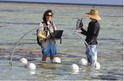
sand, were made in waters above a coral reef platform at Heron Island Reef (23° 26’ S, 151° 54’ E) in the Great Barrier Reef, Australia, using a visible and near-infrared (VNIR) spectroradiometer. The spectroradiometer, using a 10-degree fore-optic, was attached to a goniometer (radius 1 m) floating on the water surface (figure 1) and positioned in five view zenith angles (+55°, +36°, 0°, -36°, -55°) and three view azimuth angles (solar principal plane (SPP), oriented 90° and 135° from the SPP). The data was collected on the reef flat at low tide when the substrates were submerged in water depths of up to 69 cm. The spectral region of interest was from 400 to 700nm.
3. BACKGROUND THEORY
wavelengths for the same surface (Sandmeier et al., 1998b). The BRF is the ratio of the reflected radiance from a target surface in a specific direction within a field of view smaller than 20° to the reflectance of an ideal (lossless), Lambertian reference standard using identical illumination and viewing conditions, multiplied by the reference standard’s calibration coefficients (Kumar et al 2006). For a detailed explanation of reflectance quantities see Schaepman-Strub (2006).
A Lambertian surface is one where radiance is constant in all directions. However non-Lambertian BRDF’s are observable, when for non-nadir solar zenith and viewing angles the reflected radiances are not constant. This can be considered to be due to two different effects. Firstly where the surface roughness is less than λ/8cosθo, where θo is the solar zenith angle and λ is the wavelength, specular reflection will occur and will be observed as a non-Lambertian BRDF. This can be considered as a micro-
Figure 1. Field data collection - Heron Island.
surface effect. However with surfaces such as sea-grass or branching coral, different viewing angles will observe different reflectances due to the orientation of the sea-grass (for example due to current movement) or orientation of the coral (plate or branching), and the distribution of light and shade within the coral structure, although wave lensing may also cause an uneven distribution of light and shade. Mobley and Sundman (2003) indicate that non-Lambertian effects are greatest for optically very shallow water, in which case the sun’s direct beam dominates the radiance incident on the bottom surface, and retroreflection and specular reflection hotspots may be observed. As bottom depth increases, scattering causes more diffuse incident radiance and the non-Lambertian effects gradually reduce. In addition, depending on the spectral reflectance and absorption properties, different wavelengths will show greater or less non-diffuse reflectance effects.
To determine the reflectance of a surface it is first necessary to determine the incident radiation and the radiance leaving the surface. However for this study, only radiance above the water surface could be measured directly. This is the sum of the water exiting radiance and the downward sun and sky radiance that are reflected upward from the sea surface. To derive the reflectance of the benthic surface both the effects of the air-water interface, and the absorption and scattering of the intervening water, must be removed. Above water measurements are significantly influenced by surface reflection effects, predominantly sun and sky glint (Doxaran et al, 2004) and must be accurately corrected for if the radiance from the benthic surface is to be retrieved. Inaccurate corrections may result in significant uncertainities. A recommended correction is to subtract a percentage of the
incoming direct and scattered sky radiance reflected at the air- water interface (Austin, 1974, Mobley, 1999). Theoretical reflectance values can be obtained from the Fresnel equations, however these equations are derived for a perfectly level water surface. As indicated by Mobley (1999), the air-water reflectance depends on, but does not equal, the Fresnel reflectance at the surface. It is a complex factor that depends on incident radiation and viewing directions, wavelength and wind speed (Doxaran et al, 2004). Typical values for the air-water interface are 0.02 to 0.03 for clear sky and high solar elevation, and 0.05 to 0.07 for clear sky and solar zenith angles greater than 45 degrees and for overcast sky (Jerlov, 1976, Preisendorfer and Mobley, 1986).
The amount of absorption and scattering that takes place as irradiance travels through the water to the bottom surface, and then reflected back to the water-air interface, are dependent on the wavelength of the radiation, the path distance , the absorption and scattering coefficients of pure water and other constituents, and the scattering phase function that determines the direction of scattering. For pure water, absorption and scattering generally decrease through the ultraviolet wavelengths up to a wavelength of around 460nm (Jensen, 2000), when absorption rapidly increases, while scattering continues to decrease. Water absorption has a local maximum near 950nm in the visible near infrared wavelengths (Finesse Solutions, 2011) and chlorophyll a maximums between 400nm and 500nm, and at approximately 675nm (Jensen, 2000). After approximately 570nm the absorption of ocean water is dominated by water absorption and other constituents play only a small part (Jensen, 2000). At wavelengths greater than 900nm virtually all incident radiation entering the water surface is absorbed in the first half metre (for an approximate absorption value of 8.6m-1 for pure water at
900nm, transmission is only 1.35% at 0.5m, assuming an exponential decrease with depth). However in shallow waters with highly reflecting benthic surfaces, some above water measurements may include bottom surface reflectance, even at wavelengths of 900nm. For example, for a benthic surface of 100% reflectance at 0.25m depth (that is 0.5m total return path length at nadir) approximately 1% of the radiation entering the water would be returned to the surface. For shallower depths this can be much greater than 1%.
Morel and Prieur (1977) used the ratio of the upwelling irradiance to the downwelling irradiance to separate two types of water. In Case 1 chlorophyll concentration is high relative to the scattering coefficient, and in Case 2 inorganic particles are more dominant than phytoplankton. In Case 1 waters, it is useful to assume that particle absorption is dominated by phytoplankton pigments (Pegau et al, 2003). Muritorena and Guillocheau, (1996), considered outer reef areas measured in French Polynesia with chlorophyll a + pheophytin a concentrations of 0.12, 0.15 and 0.35 mg/m3 to be relatively clear and assumed them to be
Case 1 waters. Mobley et al (2004) question the value of the case 1-case 2 classification, and consider that modeling water bodies according to the constituents in the water column and the nature of the bottom boundary.
however, is reflected strongly in particular directions depending on surface roughness, but with the main beam being predominantly reflected at an equal and opposite angle to the solar zenith angle, θo. As it passes through the air/water interface it is refracted according to Snell’s Law and travels along that path, θo’, being absorbed and scattered until it reaches the bottom surface.
The transmittance of radiation through the atmosphere on a clear day is primarily related to short wavelength scattering by oxygen and nitrogen molecules. The optical thickness (τm) can be described by Rayleigh scattering which is inversely proportional to the fourth power of wavelength, so that molecular scattering is dominant in the ultraviolet and blue wavelength regions, and is scattered approximately equally in the forward and backward directions (Rayleigh scattering). Greater scattering occurs as larger particles increase (due to smoke, haze and fumes), predominantly in the forward direction. This is termed aerosol or Mie scattering, and is less wavelength dependent than molecular scattering, the optical thickness (τp) being approximately inversely proportional to wavelength. When the atmospheric particulates become much larger than a wavelength, as is common in fogs, cloud and dust, the wavelength dependence disappears. Absorption, with optical thickness τa, can also cause lowered transmittance, mainly due to water vapour and ozone at specific wavelengths.
The irradiance reaching the benthic surface will be the sum of the attenuated direct solar irradiance, the attenuated sky irradiance and the forward scattered radiation. Forward scattering is dominant for non-pure water, in a similar manner to Mie scattering. As scattering is predominantly in the forward direction and quite small for shallow waters most of the scattered radiation will reach the target area,and so effectively is not a loss. As an approximation then, it is only necessary to consider the loss from the downwelling irradiance due to absorption, rather than total attenuation, and loss due to scattering need not be considered. However when the incident radiation is reflected upwards from the benthic surface, approximately half of the upwelling irradiance is not transmitted through the water-air interface, and is returned, and hence is added to the downward flux (Morel and Mueller, 2002). This is mainly due to the upwelling radiance that passes through the surface being limited to a cone with a half angle of 48.27° for a refractive index of 1.34. For a diffuse benthic surface approximately 40% of the upwelling irradiance is reflected from the water-air interface outside the cone and approximately 8% from within the cone. Strictly speaking the added downward flux is due to the water-air surface reflectance of irradiance coming from the area immediately surrounding the target area. This two way travel, from the surrounding benthic surface to the water-air interface and back to the target area can be calculated, on average, as at an angle of approximately 60° to the vertical. Thus the total downwelling irradiance (EG(λ)) arriving at an assumed horizontal benthic surface is the sum of the attenuated direct solar radiation along the refracted path, the attenuated solar sky irradiance and the additive irradiance from the target background, and so
Rav = the average reflectance of the benthic surface
z = water depth
Ka (λ) = spectral absorption coefficient of water
ρand ρ’ = the air-water surface reflectance for direct and sky irradiance.
Note that in the last exponential term, z is multiplied by four (where 4 = 2 x sec60°) due to the two way travel from the surrounding benthic surface to the water–air interface at an average angle of 60° and then down to the target benthic surface at the same angle, and assumes attenuation is the same in both directions. Note also that Rav is an unknown quantity, and initially must be estimated.
The reflected radiance from a benthic surface measured just below the water surface is comprised of the radiance reflected from the benthic surface and transmitted directly to the detector, the radiance reflected from the benthic surface and then scattered towards the detector, and the radiance scattered into the viewing direction without interacting with the bottom. For shallow water this latter term can be negligible (Voss et al, 2003, considered depths of the order of 5m as shallow). As scattering is predominantly in the forward direction we consider that it is only necessary to account for the loss from the radiance due to absorption, as discussed previously. At the water-air interface some of the radiance will be reflected back into the water approximately in accordance with the Fresnel equations. The radiance transmitted through the surface will be less than the incident radiance below the water surface by a factor of 1/n2,
which equals 0.5569 for n = 1.34. This decrease in radiance when going from water to air is a consequence of the “n squared law of radiance” or “the fundamental theorem of radiometry” which states that the radiance divided by the square of the index of refraction (n) remains constant as light travels through regions of different n, to the extent that absorption and scattering can be neglected. Thus the radiance transmitted through the surface must be multiplied by 1/0.5569 = 1.80 to give the below water equivalent value.
Finally, added to the radiance measured above the water is the radiance reflected upwards from the water surface, into the viewing direction, resulting from downwelling direct and scattered solar radiation. The surface reflected radiance can be quite large when the viewing angle is approximately equal and opposite to the solar zenith angle. Drawing all these concepts together, the benthic surface reflectance, Rb(θ’,φ,λ) is given by
θ’ = refracted equivalent viewing angle to θ
ρ(θ] and ρ(θ’) = the air-water surface reflectance in the viewing direction θ, and water-air interface reflection at an angle of θ’.
4. FORMULAE FOR USE WITH REFERENCE SURFACE
-1
variables. However in this study only the relative irradiance and relative radiances are measured with the aid of a horizontal, diffuse, white reference panel, with an assumed reflectance of 100%. Thus the total downwelling solar irradiance, from direct and scattered skylight is effectively given a value equal to 100. Measured radiance, equivalent to Ltotal(in air) as in eqn. 2, is radiance normalized with respect to the radiance from the reference panel, measured at the same time and viewing angle.
To simplify calculations only two atmospheric conditions will be considered – a clear Rayleigh type and fully cloud covered. The relative relationships will first be derived with respect to a clear, Rayleigh scattering atmosphere. For such an atmosphere the optical thickness is inversely proportional to the 4th power of the wavelength. At 1000nm the Rayleigh optical thickness, τm, is 0.0084 and so the spectral optical thickness can be given by
τ
m(λ) = 0.0084/ λ4where wavelength is in micrometres, and forward scattering is assumed to be 50% for a clear, Rayleigh scattering atmosphere, and so
Downwelling irradiance measurements observed at 0 and 5 metre depth in deeper waters close to the study site provided estimates of the absorption coefficient , which were similar to that of pure water with 0.35 mg/ m3 of chlorophyll a + pheophytin a concentrations in coral reef waters of French Polynesia (Muritorena and Guillocheau, 1996). The absorption signature of these waters, up to 570nm, is relatively constant, and then rises steeply, with approximately the same values as pure water. For shallow waters it is not critical to have exact measures of the absorption coefficient as a change of 10% in its value will only cause a change of transmission of approximately 3% within the spectral range 400nm to 700nm, in waters of less than 0.5m. Thus linear approximations to the absorption signature, estimated from graphs by Muritorena and Guillocheau (1996), Mobley (1989), and Finesse (2011) are sufficient for most calculations –
For 400 to 550nm Ka(θ’, φ, λ) = 0.075 m-1 (8a)
550 to 700nm Ka(θ’, φ, λ) = 0.075 +0.0033(λ – 550) m-1 (8b)
700 -740nm Ka(θ’, φ, λ)= 0.57 + 0.0418(λ – 700)m-1 (8c)
[ Eo(λ)Clear100% Tθo(λ) cosθo + 0.5 Eo(λ)Clear100% ( 1- Tθo(λ))] 740 -760nm Ka(θ’, φ, λ)= 2.24 + 0.0155(λ – 740)m
(8d)
must equal 100 (or the standardized reflectance) and therefore Eo(λ)Clear100%, the spectral solar irradiance at the top of the atmosphere relative to a 100% reference panel, can be given by
Eo(λ)Clear100% =100/ [Tθo(λ) cosθo – 0.5Tθo(λ) + 0.5] (3)
Where Tθo(λ) = exp(- τm(λ) sec θo) = atmospheric transmission along solar zenith angle, θo and therefore
EG(λ)Clear100% (relative irradiance reaching the benthic surface) =
[Eo(λ)Clear100% Tθo(λ)(1- ρ’)cosθo’exp(-z Ka (λ)sec θo’) +
0.5 Eo(λ)Clear100% (1- Tθo(λ))(1- ρ)exp(-z Ka (λ))] x
[1+0.48Rav exp(-4z Ka(λ))] (4)
The new reference-surface-equivalent equation for Rb is now -
Rb(θ’,φ,λ) =1.80[Mtotal(θ,φ,λ in air) - ρ(θ]) (5) (EG(λ)Clear100%)exp[-z Ka (λ) sec θ’] [1 - ρ(θ’)]
Where Mtotal(θ,φ,λ in air) = measured radiance relative to the reference surface.
For cloudy covered conditions it is assumed all solar irradiance reaching the water surface is diffusely scattered, and not from a specific direction, therefore Eo(λ)Cloudy100% must equal 100 and so
EG(λ)Cloudy100% (relative irradiance reaching the benthic surface) =
[Eo(λ)Clear100% Tθo(λ)(1- ρ’)cosθo’exp(-z Ka (λ)sec θo’) +
0.5 Eo(λ)Clear100% (1- Tθo(λ))(1- ρ)exp(-z Ka (λ))] x
[1+0.48Rav exp(-4z Ka(λ))] (6)
and therefore
Rb (θ’,φ,λ) = 1.80[Mtotal(θ, φ,λ in air) - ρ(θ]) (7) (EG(λ) Cloudy100%)exp[-z Ka (λ) sec θ’] [1 -ρ(θ’)]
760 - 800nm Ka(θ’, φ, λ)= 2.55 – 0.0135(λ – 760)m-1 (8e)
800 - 920nm Ka(θ’, φ, λ)= 2.01 + 0.0667(λ – 800)m-1 (8f)
One of the most critical variables in eqns. 5 & 7 is ρ(θ), the surface reflectance in the viewing direction above the water. Any errors in the determination of this variable can cause a significant error in the derived value of Rb(θ’,φ,λ), particularly when Rb is a low value. Purkis and Pasterkamp (2004) corrected the above water measured values by applying a correction equal to the measured value at 850nm. They assumed zero reflectance in that spectral region due to the large absorption by pure water and that sky reflectance was wavelength independent. The basis for this correction is that the measured value above the water is only composed of surface reflectance, and that this should be the same for all wavelengths when the measurements are taken at the same time. At 850nm the absorption coefficient of pure water is approximately 5 and, whilst large, in shallow waters, with a bright benthic surface, the measure taken above the water may also contain radiance from the bottom surface, and scattering from the water itself. To ensure that only radiance reflected from the water surface, and not from below, is measured, it was considered preferable to use the 900nm measurement, as water absorption is approximately 4 to 5 times greater than at 850nm, and is close to a local maximum. Thus subtracting the 900nm value from the measured value, then [Mtotal(θ, φ,λ in air) - ρ(
θ]) in eqns. 5 & 7 can be replaced by the corrected value McorrClear(θ,φ,λ, in air), where McorrClear(θ,φ,λ in air) is the above
water measured value for wavelength λ, less the 900nm value.
assuming this is the same for all view angles, then a “corrected” 900nm value equal to McorrClear(θ,φ,900nm in air) less the
McorrClear(θ,φ,λ in air) lowest 900nm value, plus 2.00, is used.
5. CALCULATED REFLECTANCE AND BIDIRECTIONAL REFLECTANCE FACTOR
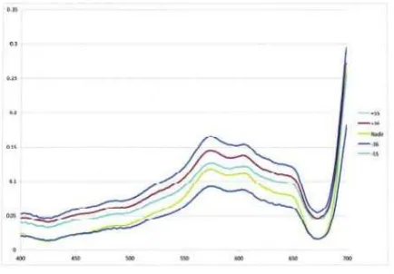
The reflectance at all view angles (+55°, +36°, 0°, -36°, -55°) in the solar principle plane, and the normalised bidirectional reflectance factor, were calculated for Arborescent (closed - branching) and Corymbose coral (plate-like) and microalgae over sand. Measurements for the corals were observed in cloudy conditions, (solar zenith angle, 45° for corymbose and 15° for arborescent), while the microalgae measurements were in full sun at 33° solar zenith angle. Wind speed for the two corals was 11 knots and the microalgae, 1-2 knots. Wave heights were 0 to 0.1m, however buoys attached to the goniometer had a dampening effect within the gonimeter frame. Graphs of reflectance and the normalised bidirectional reflectance factor are shown for each surface in figures 2 to 7, from 400 to 700nm. The graph legend shows +55°, +36°, 0°, -36°, -55° with 55° at the top through to -55° at the bottom of the legend.
Figure 2: Reflectance of arborescent coral in the solar principal plane for five view angles.
Figure 3: Normalised bidirectional reflectance factor for arborescent coral - solar principal plane for five view angles.
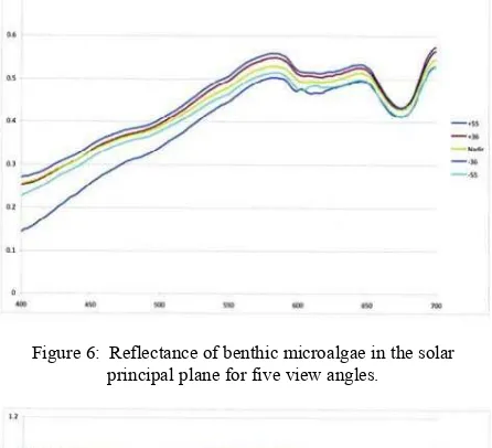
It can be seen from the graphs that the reflectance of the corals are distinctly different to benthic microalgae which has a higher
reflectance across all wavelengths, but with all having strong absorption in the 675nm chlorophyll absorption region. The triple-peaked (570, 600 and 670nm) reflectance reported by Hochberg and Atkinson (2000) is clearly visible in both coral curves. The corals and benthic microalgae have similar reflectance curves to those of Montipora and Porites corals (encrusting and massive corals) and sediment with benthic microalgae, as shown by Joyce and Phinn (2003) for samples also observed at Heron Island. In general all surfaces show a greater reflectance for those measurements taken with the sun behind (+ve view angles) due to the retroreflection “hotspot” indicating bidirectional reflectance. The normalised bidirectional reflectance factor curves show more clearly the bidirectional effect with strong maxima near chlorophyll absorption regions for both corals (figures 3 and 7) but not for the benthic microalgae (figure 7). It is also shown that the arborescent coral has a greater normalised BRF than corymbose near the chlorophyll absorption at 675nm, possibly due to the latters branching nature, while corymbose coral has a significant maximum at 550nm. These differences should aid discrimination.
Figure 4: Reflectance of corymbose coral in the solar principal plane for five view angles.
Figure 5: Normalised bidirectional reflectance factor for corymbose - solar principal plane for five view angles.
6. SUMMARY AND CONCLUSIONS
Figure 6: Reflectance of benthic microalgae in the solar principal plane for five view angles.
Figure 7: Normalized bidirectional reflectance factor for benthic microalgae in the solar principal plane for five view angles.
adjoining Heron Island show that their reflectance is not Lambertian and that the bidirectional reflectance and normalized bidirectional reflectance factor may be sufficiently different to be used as a means of discriminating and classifying coral and other reef substrates. Further bidirectional reflectance research is being undertaken for other coral data from Heron Island as a basis for developing classification procedures for data acquired by CHRIS (Compact High Resolution Imaging Spectrometer).
7. REFERENCES
Austin, R.W., 1974, Inherent spectral radiance signatures of the ocean surface, Ocean Color Analysis, Scripps Institute of Oceanography, La Jolla, CA, pp.195.
Doxaran, D., Nagur Cherukuru, R.C., and Lavender, S.J., 2004, Estimation of surface reflection effects on upwelling radiance field measurements in turbid waters, Journal of Optics A: Pure and Applied Optics, 6, pp. 690-697.
Finesse Solutions, 2011, finesse.com/files/pdfs/app-tech- notes/Trucell.TN.CellDensityPrimer.pdf, Figure 2 pp 2
Hochberg, E.J. and Atkinson, M.J., 2000, Spectral discrimination of coral reef benthic communities, Coral Reefs, 19, pp. 164-171.
Jensen, J.R., 2000, Remote Sensing of the Environment, An Earth Resource Perspective, Prentice Hall, New Jersey, pp. 362-383.
Jerlov, N. G. 1976, Applied Optics, Elsevier Sc., Amsterdam.
Joyce K.E. and Phinn S.R., 2003, Hyperspectral analysis of chlorophyll content and photosynthetic capacity of coral reef substrates, Limnology and Oceanography, 48, pp 489-496.
Kumar, L., Schmidt, K., Dury, S. and Skidmore, A., Imaging Spectrometry and Vegetation Science, in Imaging Spectrometry, ed. Van der Meer, F.D. and de Jing, S.M. (Springer, 2006) pp 12.
Mobley, C.D., 1989, A numerical model for the computation of radiance distributions in natural waters with wind-roughened surfaces, Limnology and Oceanography, 34(8), pp. 1473-1483.
Mobley, C.D., 1999, Estimation of the remote-sensing reflectance from above-surface measurements, Applied Optics, 38, pp. 7442-55.
Mobley, C.D., Stramski, W., Bisset, W.P. and Boss, E., 2004, Optical modeling of ocean waters: Is the case-1 case-2 classification still useful, Oceanography, 17(2), pp 60-67.
Mobley, C.D. and Sundman, L.K., 2003, Effects of optically shallow bottoms on upwelling radiance: Inhomogeneous and sloping bottoms, Limnology and Oceanography, 48, pp.329-336.
Morel, A. and Mueller J.L., 2002, Normalized water-leaving radiance and remote sensing reflectance: Bidirectional reflectance and other factors, NASA/TM-2003-211621IRev4- Vol.4.
Morel, A. and Prieur, L., 1977, Analysis of variations in ocean color, Limnology and Oceanography, 22, pp. 709-722.
Muritorena, S. and Guillocheau, N., 1996, Optical properties of water and spectral light absorption by living and non-living particles and by yellow substances in coral reef waters of French Polynesia, Marine Ecology Progress Series, Vol.131, pp245-255.
Pegau, S., Zaneveld, J.V.R., Mitchell, B., Mueller, G., Kahru, J.L., Wieland, M., Malgorzat, J., and Stramska, M., 2003, Inherent Optical Properties: Instrumentation, Characterizations, Field Measurements and Data Analysis Protocols, NASA.
Preisendorfer, R.W. and Mobley, C.D., 1986, Albedos and glitter patterns of a wind-roughened sea surface, Journal of Physical Oceanography, 16, pp. 1293-1316.
Purkis, S.J., and Pasterkamp, R., 2004, Integrating in situ reef- top reflectance spectra with Landsat TM imagery to aid shallow- tropical benthic habitat mapping, Coral Reefs, 23, pp. 5-20.
Sandmeier, St., Müller, Ch., Hosgood, B. and Andreoli, G., 1998b, Physical mechanisms in hyperspectral BRDF data of grass and watercress, Remote Sensing of Envir., 66, pp 222-223
Schaepman-Strub, G., Schaepman, M.E., Painter, T.H., Dangel, S., and Martonchik, J.V., 2006, Reflectance quantities in optical remote sensing – definitions and case studies, Remote Sensing of Environment, 103, pp. 27-42.