Critical Link Identification of Bilge Pump Wiring Using
Qualitative Fault Tree Evaluation
Muhamad Ari[1], Rona Riantini[2] ,Dept. of Shipbuilding Engineering[1] ,Dept. of Marine Electrical Engineering[2] Shipbuilding Institute of Polytechnic Surabaya (PPNS)
Surabaya, Indonesia [email protected]
Abstract-There are several causes that were identified as the reasons of bilge pump system failure. One of the subsystems that frequently causing the bilge pump failure is its electrical system. This paper tries to identify critical link of three types of bilge pump wiring: commonly used wiring, the modified one using relay to minimize wire size, and the one using double float switches to prevent the pump from running on and off in short bursts. Qualitative Fault Tree Analysis was employed to identify minimal cut sets, focusing on automatic system failure as top event. The result shows that in terms of critical link, commonly used wiring is better than two other modification wiring. Unfortunately, all of three cut sets can be categorized as single failure point, because it only contain one element in one cut sets, if one of them fails it will directly lead to the top event.
Keywords—bilge pump wiring; qualitative Fault Tree Analysis; critical link
I. INTRODUCTION
There were numerous accidents involving bilge pump system failure. As an example, Vixen, 6.5 m steel hull passenger ferry was foundered around 50 m from the shore of Ardlui Marina, Scotland. The MAIB (Marine Accident Investigation Board) investigation found that the bilge alarm was not working and the bilge pump no longer worked in its automatic mode [1]. Moreover, Terry, J. from University of Alaska [2] stated that a national study of pleasure boats found that more vessels sank at the dock than at sea. Major cause of both types of sinking is improper sizing, installation, and maintenance of bilge pump. The successful bilge pump system is depend on many factors such as pump selection and installation, power sources, wiring, and switches. However, contrary to common belief, the pumps themselves infrequently fail; it is the electrical system from which they operate that is usually the cause of the failure [3]. Electrical faults and flaws offer the greatest opportunity for a bilge pump failure [4].
Bilge pumps usually are wired to automatic switches; either incorporated in the pump body itself, or mounted separately [2]. When the automatic switch, such as float switch, determines that bilge water has risen to a predetermined level, bilge pump will turn on automatically. A switch panel is also being provided to allow the operator turning the pump on and off manually.
Commonly used wiring for automatic system is a series connection from battery, float switch and bilge pump. An idea
raised by Rosenvelt to use a relay in order to reduce the load on the float switch [5]. This modification will give advantage in reducing size of copper wire used to the float switch. However, there is a question whether this relay will become a weak link in this system. Another modification was being considered in an online discussion forum. The modification arose to overcome the drawback of commonly used wiring which sometimes only removed a small amount of water and ran at frequent intervals and drains the battery [6].
In this paper, Qualitative Fault Tree Analysis is employed to analyze critical link or weak link in the bilge pump system wiring, both the commonly used wiring and the other modified ones. Fault tree analysis will produce minimal cut set which show us minimum combination of basic event that lead to the automatic system failure of bilge pump electrical system.
II. FAILUREOFBILGEPUMPSYSTEM
A. Importance of Bilge Pump System
Bilge pump system was installed not only for the reason of stability but also to reduce odours and corrosion. In point of fact, although standard bilge pump installation is commonly considered as the first mitigation action against catastrophic flooding, but most of them are designed for only incidental water removal such as rain, the occasional wave over the gunwale or extremely small leak. However, in an emergency situation due to flooding, the primary task of the crew is to stop the leak, and a good bilge pump will allow some time to accomplish this [4]. Nevertheless, it is still extremely important to keep the bilge as dry as possible, especially for the small boat. Bilge pump system should be able functioning properly since the small boat are more likely to ship water
B. Cause Of The Bilge Pump System Failure
There are several causes identified as the reason of bilge pump system failure. In general it will be discussed in two main causes, the failure of the pump and the failure of the electrical system.
(a) Failure of the Pump
There are several categories of pump, such as rubber impeller, diaphragm, and centrifugal. Each of them has its own characteristic, which shall be installed properly. Neither the impeller nor diaphragm pump is submersible; therefore, they must be installed well above bilge water level, or wherever likely water accumulation and exposure. Centrifugal pump is submersible and by far is the most familiar. However, it won’t pump air; consequently it should be installed so that its base is submerged [4]. Centrifugal and diaphragm pumps can be run dry for a period of time without damage, whereas a flexible-impeller pump will burn up within a minute or two [2].
Miscalculation of total head also may lead to the failure of the pump. Since bilge pump capacity is commonly listed as “open flow” (the figures account for no vertical lift and no hose friction or discharge outlet restriction), actual flow rate under real operating condition are usually lower [2]. For all without removing any water [4].
Although some types of pumps are more sensitive to debris than the other, debris-induced clogging still being the dangerous enemy which can lead to the pump failure.
(b) Failure of the Electrical System
A bilge pump is only as good as the battery and wiring that supply power to it. Usually there is no problem if batteries are charged daily, either by alternator or shore power. But the batteries alone cannot be expected to keep the bilge dry for long [2].
In addition, bilge pump is one of critical equipments which is required for safety, and its efficient operation is critical. The standards allow only a 3 percent maximum voltage drop for these critical equipments. Voltage drop is simply the reduction of voltage in a circuit caused by amperage working to overcome resistance. For example, When a bilge pump is turn on, the current (amperage) encounters resistance (ohms) in a circuit caused by wiring that is too small or by corroded terminals, the wattage is converted to heat (wattage is more properly called joules here) [7]. This problem will reduces pump performance, and can cause overheating.
Float switch is also prone to being jammed by debris and sticking in either on the on or off position, unless it is protected by a guard or housing. It must be installed where it is easily accessible for inspection and cleaning. Moreover,
some lower priced switches aren’t rated for the current
overload that can result from a partially obstructed impeller [2].
There is always a possibility of mistake in wiring pumps. One of common mistakes is to wire them after the shut off switch or the main circuit breaker; which mean, when the main power is switched off, the bilge pump also being shut down [3]. This is why boat not only sinks at the sea but also at the dock.
III. FAULTTREEANALYSIS
Fault Tree Analysis is a simple, effective reliability method which is recognized internationally. It is being used for guiding system optimization and analyzing the weak links of the system [8]. A fault tree may simply be described as a logical representation of the relationship of basic fault events that may cause a specified undesirable event, called the “top event,” to occur. It is depicted (i.e., fault tree) using a tree structure with logic gates such as OR and AND [9].
FTA can be applied to all new or modified products in all design phases, as an analytical tool for identification of potential design problems, including those early phases where information on the design details is incomplete. Those early efforts would then be extended as more information on the system design and its components becomes available [10]. The most important advantage of the fault tree approach is that it begins with a top event. This top event is selected by the user to be specific to the failure of interest [11].
However, Fault Tree also has some disadvantages which have to be considered while using this method. For any reasonably complicated process the fault tree will be enormous which involving thousands of gates and intermediate events.. Fault trees of this size require a considerable amount of time, measured in years, to complete. More complete fault trees are usually developed by more experienced engineers. Fault trees also assume that a particular item of hardware does not fail partially. Also, the approach assumes that a failure of one component does not stress the other components, resulting in a change in the component failure probabilities. In addition, the developer of a fault tree can never be certain that all the failure modes have been considered. Fault trees developed by different individuals are usually different in structure; the different trees generally predict different failure probabilities. This inexact nature of fault trees is a considerable problem [11]
A. FTA Chart
There are several symbols used in developing the FTA chart in this paper. Primary event, intermediate event and gate symbols are described in Table 1. Primary events, which are at the bottom of fault tree, are those events, which, for one reason or another have not been further developed. In addition, there are two basic types of fault tree gates: the OR-gate and the AND-gate. The other gates are really special cases of these two basic types [12].
Table I. FREQUENTLY USED SYMBOLS FOR A FAULT TREE [10]
Basic event : event or state that cannot be further developed
Undeveloped event : A primary event that represents a part of the system that is not yet developed
Top Event : outcome of combinations of all input events
Intermediate Event : event that is neither a top event nor a primary event
AND-gate : The output event occurs only if all of the input events occur
OR-gate : The output event occurs if any of the input events occur
Transfer Gate : Gate indicating that this part of the system is developed in another part or page of the diagram
B. Qualitative Fault Tree Evaluation
Qualitative fault tree evaluation is the process of finding the combinations of basic events which, if they occur, cause the top event occurrence. The rules of the Boolean algebra are applied to obtain the equation for top event which consists of sum of products of basic events. When the sum of products of basic events is expressed from Boolean equations of the fault tree, each element of the sum includes the product of a certain number of basic events. Those basic events together represent a minimal cut set. The minimal cut sets are combinations of the smallest number of basic events which if occur simultaneously, may lead to the top event [13].
The number of basic event in the minimal cut sets should be as much as possible to avoid triggering the top event. Minimal events or their combinations, cause the top unfavorable event (outcome).
In generating minimal cut sets, a systemized algorithm called MOCUS (Method of Obtaining Cut Sets) [14] sometimes is being used; however, since the circuit is not too complicated, in this paper Boolean equation is employed to establish the cut sets of a fault tree. Table 2 described the Boolean algebra rules [15].
Table II. RULES OF BOOLEAN ALGEBRA Rules Mathematical Form
Commutative A . B = B . A
Another important term in the fault tree terminology is the so-called path set. A path set assembles a set of causes with the characteristic that non-occurrence of the causes in the path sets ensure that the top event does not occur [14].
IV. FAULTTREEANALYSISOFBILGEPUMP
WIRING
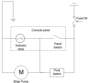
If submersible pump, such as centrifugal pump, is being used, both the pump and the float switch will be located in the bottom of the bilge. While impeller and diaphragm pump will be located above the deck since none of them are submersible.
M
FloatFigure 1. Commonly used bilge pump wiring
Figure 2 shows the modification of commonly used wiring with employing a relay. When the float switch is closed, the current will flow through the relay coil and activated the relay contact, which starting the bilge pump motor. This modification idea was risen by Rosenvelt [5] in order to reducing size of copper wire used to the float switch.
M
Float Switch Indicator
lamp
Bilge Pump
Panel Switch
Fuse/CB
Relay coil Relay
contact
Figure 2. Bilge pump wiring Modification using Relay
As shown in Figure 1, both the float switch and the wire shall have current carrying capacity higher than the amperage of the pump. In the other hand, Figure 2 shows that the wire connected to the float switch is only being used to activate the relay coil.
Figure 3 shows the modification using upper and lower float switch. Figure 3 is a redrawing from circuit created by Jim Dearden [6] in an online discussion forum in order to prevent the pump from running on and off in short bursts. The idea is introduced by Sam, who worked in a sailboat. He found the drawback to the commonly used design which only removed a small amount of water and ran at frequent intervals. This drains the batteries and causes excessive wear and tear. The idea is to use upper and lower float switch so it doesn't turn on until the upper float switch closes and stays on until the lower switch opens.
M Lower Float
Switch Indicator
lamp
Bilge Pump
Panel Switch
Fuse/CB
Relay coil Relay contact
Upper Float Switch
Figure 3. Bilge pump wiring using Upper and Lower Float Switch
B. FTA Chart Of The Wiring And Animal Cut Set
This paper compares three type of the wiring. However, the difference will only occur in automatic system. Manual operated system is exactly the same in all type of wiring.
Bilge pump system fail
Bilge pump system wiring fail
Pump fail Battery fail
A
X Panel switch fail to
close
C
Panel switch damage
Person on board fail to
detect PS Cable
wiring fail
B
Automatic system fail
1
2
3
Figure 4. FTA Chart of Bilge Pump System
As shown in Figure 4, three types of wiring will have same FTA chart for top event failure of bilge pump. Bilge pump system will fail if pump, battery or system wiring is fail. Bilge pump system wiring will fail if both manual panel switch and automatic system are fail.
Transfer gate X at figure 4 will be continued with three different FTA chart for each type of wiring. The comparation of three types wiring will be analyse through figure 5 – 7 with top event the failure of automatic system.
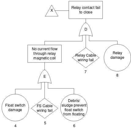
Float switch fail to
Figure 5. FTA Chart of Automatic System Failure in commonly used bilge pump wiring
Minimal cut set of commonly used wiring FTA chart is as follows: D = (4+5+6)
There are three cut sets are identified and all of them are single failure points, which categorized as the critical links in the system. This means either one of the causes is happened or the automatic system will fail.
E
Figure 6. FTA Chart of Automatic System Failure in bilge pump wiring modification using relay
In other case, Figure 6 shows the FTA chart of Automatic System Failure in bilge pump wiring modification using relay. Minimal cut set of FTA chart in Figure 6 is as follows
D = (E+7+8) D = (4+5+6+7+8)
There are five single failure points are identified in this circuit: float switch internal failure, failure of float switch wiring, debris/sludge, relay internal failure and the failure of relay cable wiring.
The last type of wiring discussed in this paper is the one using double float switch. Refer to Figure 3, the pump will turn on if current flow from battery through upper switch and through
Figure 7 FTA Chart of Automatic System Failure in bilge pump wiring modification using upper and lower float switch
Transfer gate Y is continued in figure 8 to describe how are the mechanisms that lead to the failure of circuit between upper switch and the pump. AND-gate F is used because current can flow through lower float switch or through contact relay. That is mean that the circuit between upper switch and the pump will be fail only if both Lower float switch and relay are fail.
Contact Relay fail
Figure 8. FTA Chart of Automatic System Failure in bilge pump wiring modification using upper and lower float switch (cont.)
Minimal cut set of figure 7 and figure 8 is as follows:
D = E + F
There are nine cut sets identified for this wiring type. Three of them are single failure point which can be categorized as the weak link of the system.
C. Discussion
Commonly used wiring in bilge pump system is the simplest one; as the float switch is close so the current will flow from the battery to the pump through the float switch. However, from the result of FTA, this type of wiring has three minimal cut sets that contain single element only (single failure point); internal failure of float switch, failure of float switch cable wiring or debris/sludge that prevent the float switch to be activated. If one of them occurs, top event will happen.
Bilge pump wiring modification using relay is being claimed to have reduction in cable size. However, the cost for small ships is debatable and it is being question whether the relay will be the weak link of the system [5]. The result of qualitative FTA shows that there are five single failure points,
which is worst than commonly used wiring. Nevertheless, relay cannot be said as the only weak link, since all of the cut sets have only one element.
Last type of wiring discussed in this paper is using two float switches, which give advantage in preventing the pump from running on and off in short bursts. There are nine minimal cut set being identified from FTA, 3 of them are single failure points (the same as commonly used wiring) and the other five cut sets contain 2 element/basic event. In terms of critical link identification, this wiring is worse than commonly used wiring, but better than the one using one float switch and one relay. Although there are five more combinations of event in minimal cut set, they are still required two element failures in the same time to lead to the top event.
Further discussion comparing commonly used wiring and the modification using double float switch still can be debatable, especially in reliability analysis. Although three single failure points being identified are similar (internal failure of float switch, failure of float switch cable wiring or debris/sludge that prevents the float switch to be activated); the float switch position is vertically quite different. Logically the condition of debris and sludge in the bilge with different vertical position will be dissimilar.
Nevertheless, in order to minimize the failure of bilge wiring system, the bilge has to maintain to be as clean as possible and all the components especially float switch shall be at a high quality product. In addition, all the wiring shall use approved marine cable and installed properly.
V. CONCLUSIONS
In the present paper Qualitative Fault Tree Analysis is employed to identify the critical link in the system of three type bilge pump wiring. It is focusing on automatic system failure and put it as the top event.
The result shows that in terms of critical link, commonly used wiring is better than two other modifications wiring, which contain three cut sets. However, all of three cut set being identified can be categorized as the weak link, because they only contain one element in one cut sets, if one of them fail it will directly lead to the top event.
REFERENCES
[1] MAIB, “Report on the investigation of the foundering of the small passenger ferry Vixen in Ardlui Marina, Loch Lomond on 19 September 2012,” MAIB, Southampton, 2013.
[2] T. Johnson, “Choosing and Installing Bilge Pumps,” Boatkeeper, 2001.
[3] D. H. Pascoe, “All about Bilge Pump,” D. H. Pascoe & Co., Inc., [Online]. Available: http://marinesurvey.com/yacht/bilge_pumps.htm. [Accessed 13 July 2014].
[4] S. D'Antonio, “Plumbing the Depths; Electric bilge pump systems debunked and done right,” Proffessional Boatbuilder, no. 147, 2014. [5] P. Rosenvelt, “Letters responding article "Plumbing the depths",”
Proffessional Boatbuilder, no. 148, p. 4, April/May 2014. [6] “Dual Float Switches for a Boat's Bilge Pump,” 26 June 2013.
[Online]. Available:
http://electronics.stackexchange.com/questions/74155/dual-float-switches-for-a-boats-bilge-pump. [Accessed 23 August 2014]. [7] E. Sherman, Powerboaters' Guide to Electrical System, 2nd ed.,
Camden, Maine: McGraw-Hill, 2007.
[8] Y. Wang, Q. Li, M. Chang, H. Chen and G. Zang, “Research on Fault Diagnosis Expert System Based on the Neural Network and the Faul Tree Technology,” Procedia Engineering, vol. 31, pp. 1206-1221, 2012.
[9] B. S. Dhillon, Human Reliability and Error in Transportation System, Ottawa: Springer, 2007.
[10] International Electrotechnical Commission, IEC 61025 : Fault Tree Analysis, Second edition ed., 2006.
[11] D. A. Crowl and J. F. Louvar, Chemical Process Safet; Fundamental with Application, 2nd ed., New Jersey: Prentice Hall, 2002. [12] W. E. Vesely, F. F. Goldberg, N. H. Roberts and D. F. Haasl, Fault
Tree Handbook, Washington D.C.: US Nuclear Regulatory Commission, 1981.
[13] M. Cepin, Assessment of Power System Reliability; Methods and Application, London: Springer, 2011.
[14] S. Kristiansen, Maritime Transportation; Safety management and Risk Analysis, Oxford: Elsevier, 2005.
[15] Center for Chemical Process Safety, Guidelines for Chemical Process Quantitative Risk Analysis, 2nd ed., Center for Chemical Process Safety, 2000.
Halaman ini sengaja dikosongkan