Metalurgi (2016) 1: 1-68
M
ETALURGI
Available online at www.ejurnalmaterialmetalurgi.com
M
ETALLURGICAL
A
SSESMENT
O
F
A
B
ROKEN
G
EARBOX
I
NTERMEDIATE
S
HAFT
O
F
A
R
ECIPROCATING
C
OMPRESSOR
D. N. Adnyana
Department of Mechanical Engineering, Faculty of Industrial Technology The National Institute of Science and Technology (ISTN)
Jl. Moh Kahfi II, Jagakarsa, Jakarta Selatan 12640 E-Mail: * [email protected]
Masuk Tanggal : 24-01-2016, revisi tanggal : 13-04-2016, diterima untuk diterbitkan tanggal 30-04-2016
Abstract
This paper presents the results obtained from the metallurgical assessment on a broken gearbox intermediate shaft of a reciprocating hydrogen make-up compressor. This gearbox intermediate shaft is splined at its end and made of a machinery steel of AISI 4340. This gearbox intermediate shaft was reported to have been failing frequently since the compressor was installed about thirty years ago. In the early operation during which the intermediate shaft was still supplied as original part, the shaft was reported to last for about three years, but later after the shaft was made by local manufacturer, its service life decreased significantly to less than one year or even only a few months. To perform metallurgical assessment, a number of specimens were prepared either from the broken shaft or from the unbroken shaft for laboratory examinations including macroscopic examination, chemical analysis, tensile test, metallographic examination, hardness test, and SEM (scanning electron microscopy) examination equipped with EDS (energy dispersive spectroscopy) analysis. Results of the metallurgical assessment obtained showed that the gearbox intermediate shaft had experienced predominantly to fatigue fracture caused by a high nominal stress due to the combination of shear stress, bending stress and torsion stress. The fatigue fracture was initiated from the tooth root of the shaft splines where high stress concentration present, and propagated into two directions, one in the anticlockwise transverse and radial direction approximately 45°to the shaft axis, and the other was to form a radial “whirlpool” crack pattern prior to the fast growing final fracture to form cup and cone like fractures. The high nominal stress experienced by the intermediate shaft during its operation may have been caused by the low strength of the material used for the intermediate shaft. The results of chemical analysis obtained showed that the material used for the intermediate shaft was very much close and met to the material specification of AISI 4340. However, from the results of mechanical tests obtained, the material used apparently did not meet to the material specification of AISI 4340 in the as-normalized condition. The low mechanical property of the intermediate shaft material in comparison with the standard material was very much influenced by its microstructures which contained a mixture of bainite or tempered martensite, pearlite and ferrite. The presence of the pearlite and especially ferrite in the microstructures could reduce the mechanical properties quite significantly and this may have been associated with some improper manufacturing and/or heat treating processes applied to the shaft. In addition, the acceleration of fatigue fracture occurred on the intermediate shaft was likely not contributed by any corrosion.
Keywords: Gearbox intermediate shaft, Reciprocating compressor, Fatigue fracture, Machinery steel of AISI 4340
Intisari
20 | Majalah Metalurgi, V 31.1.2016, ISSN 0126-3188/ 1-68
dispersive spectroscopy). Hasil pengujian dan analisis metalurgi yang diperoleh menunjukkan bahwa gearbox poros menengah telah mengalami patah lelah yang disebabkan oleh tegangan nominal yang tinggi akibat kombinasi tegangan geser, tegangan lentur dan tegangan torsi. Patah lelah diawali dari bagian akar gigi poros menengah tersebut yang merupakan daerah dengan pemusatan tegangan yang tinggi dan merambat dalam dua arah, salah satunya pada arah berlawanan dengan arah jarum jam secara melintang dan radial sekitar 45° terhadap sumbu poros, dan lainnya merambat secara radial dengan membentuk pola retak/patahan seperti “pusaran kolam” sebelum terjadi pertumbuhan yang cepat pada saat patah akhir yang membentuk patahan seperti mangkuk dan kerucut. Tegangan nominal yang tinggi yang dialami oleh poros menengah selama operasi kemungkinan disebabkan oleh kekuatan material poros yang rendah. Hasil analisa kimia yang diperoleh memperlihatkan bahwa material poros menengah tersebut adalah hampir mendekati dan sesuai dengan spesifikasi material menurut AISI 4340. Akan tetapi, dari hasil uji mekanis yang diperoleh sangat jelas menunjukkan bahwa material yang digunakan tidak sesuai dengan spesifikasi AISI 4340 dalam kondisi diberi perlakuan panas normalisasi. Rendahnya sifat mekanis dari poros menengah tersebut dibandingkan dengan material standar sangat dipengaruhi oleh struktur mikronya yang terdiri dari campuran bainit atau martensit temper, perlit dan ferit. Adanya struktur perlit dan terutama ferit dalam struktur mikro material poros menengah tersebut dapat menurunkan sifat mekanis secara signifikan dan ini kemungkinan dapat dikaitkan dengan ketidak sesuaian dalam proses manufaktur dan/atau proses laku panas yang diberikan pada poros tersebut. Disamping itu, percepatan patah lelah yang terjadi pada poros menengah tersebut sepertinya tidak ditunjang/dibantu oleh proses korosi.
Kata Kunci: Gearbox poros menengah, Kompresor torak, Patah lelah, Baja permesinan AISI 4340
1.
P
ENDAHULUANThis paper presents the results obtained from the metallurgical assessment on the broken gearbox quill (intermediate) shaft of a
hydrogen make-up compressor. The
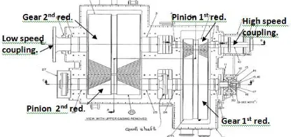
compressor was installed and has been in operation for about 30 years. The compressor utilizes a steam turbine to drive a high speed coupling at maximum design speed of 5970 rpm. This high speed coupling is connected to a double reduction gearbox which is designed to transmit maximum power rate of 6725 kW (see Fig. 1). This double reduction gearbox is provided with a quill shaft between the first reduction gear and second reduction pinion with reduced speed of 890 rpm. Through the second reduction gear which is connected to a low speed coupling, the speed is further reduced down to 300 rpm. This low speed coupling is used to drive a flywheel and six cylinders reciprocating compressor. As seen in Figs. 1 and 2, the double reduction gearbox consists of a high speed pinion (or pinion first reduction), a high speed gear (or gear first reduction), a low speed pinion (or pinion second reduction), and a low speed gear (or gear second reduction). As mentioned above, the pinion second reduction assembly shown in
Fig. 2 is equipped with a gearbox quill (intermediate) shaft which is installed inside the pinion shaft (see also Fig. 3). The quill shaft shown in Fig. 3 is splined at its end and the contact engagement is made with a coupling hub to transmit the torque. During its operation, the compressor is designed to accommodate for 1 to 5 steps of load change conditions and therefore the level of load cycles or dynamic loads occurred on the gearbox parts and the quill shaft as well are generally quite significant.
Figure 1. General drawing of gearbox assembly of the compressor under study
Metallurgical Assesment Of A Broken Gearbox Intermediate Shaft …../ D.n Adnyana | 21
as original part, the quill shaft was reported to last for about 3 years, but later after the quill shaft was made by local manufacturer, its service life decreased significantly to less than one year or even only a few months. Several effort and mitigation have been made to improve and extend the quill shaft service life, but none has been solving the problem successfully.
Figure 2. General drawing of pinion second reduction and gear first reduction assembly
Figure 3. A new quill shaft and its installation into the pinion second reduction assembly
Most of the effort that have been made
included modification in geometry and
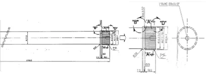
dimension of the splined shaft, and up grading the shaft material from the original AISI 4140 to AISI 4340. From the documented drawing, there were two time design changes of the splined shaft that have been recorded. One of the design changes shown in Fig. 4 was recorded and made in March 2003 using the specification as follows: spline pitch diameter: 163.57 mm, shaft body diameter: 177.8 mm, engagement or contact length of the splines: 90.1 mm and material used AISI 4340 (after being machined, its hardness should be in the range of 321 to 375 HB). In addition to the above mentioned design change, there was likely other design change that has been made but was not well documented.
Due to the quill shaft still persists to fail although a number of design changes have been made, it is time to consider for performing a more systematic study and assessment on the gearbox quill shaft which include a number of testing and examination either performed on site or in the laboratory. It is hoped that the outcome of this assessment will be useful to develop a remedial action that could improve and extend the service life and reliability of the
quill shaft and eventually could eliminate significantly the unnecessary down time production losses.
Figure 4 A recorded dimensional drawing of compressor gearbox quill (intermediate) shaft
The purpose of this metallurgical
assessment has been to verify the material properties and to determine whether the material used for the quill shaft met the specification or suitable for its operating condition, and to establish the type, cause and mode of failure of the broken quill shaft, and based on the determination some corrective or remedial action may be initiated that will prevent similar failure in the future.
2.
E
XPERIMENTALP
ROCEDUREIn performing this metallurgical assessment, one broken quill shaft A and one unbroken quill shaft B have been used for laboratory examinations. The broken quill shaft A consisted of two damage pieces of the cup like fracture and the cone like fracture of the splined shaft, respectively (see Figs. 5 and 6). A number of specimens were made from the broken quill shaft and from the unbroken quill shaft for various laboratory examinations. Macroscopic examination on fracture surfaces of the broken quill shaft was performed using a Stereo Microscope, whereas chemical analysis on the prepared samples was carried out using an Optical Spark Emission Spectrometer. The purpose of this chemical analysis was to determine whether the material used for the broken quill shaft met the specification or suitable for its operating condition. In addition, tensile tests were also performed on the specimens made from the unbroken quill shaft B using an Universal Testing Machine.
Furthermore, metallographic examinations
22 | Majalah Metalurgi, V 31.1.2016, ISSN 0126-3188/ 1-68
examination using Vickers hardness method at a load of 5 kg (HV 5). Moreover, examination on some fracture surfaces of the broken quill shaft A was also performed using a Scanning Electron Microscope (SEM) to determine the fracture topography and nature of the failure. This SEM examination was equipped with an
EDS (Energy Dispersive Spectroscopy)
analysis to detect the presence of any viable defect or corrosion by-products. To ensure that no any deposit or corrosion by-products may have been removed from the fracture surface, the SEM/EDS specimens had not been cleaned-up using methanol or ethanol.
3.
R
ESULTSA
NDD
ISCUSSIONA.Visual Examination and General Physical
Features
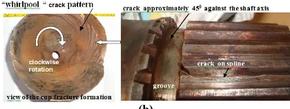
The broken quill shaft A shown in Figs. 5 and 6 consisted of two separated damage portions, one in a cup like fracture and the other in a cone like fracture. These two fracture portions of the broken quill shaft A can be reconstructed or reunited into a damage part approximately represented in Fig. 6. The cup like fracture shown in Fig. 5 is fully cracked on its external surface, in which the crack connected along one of its spline tooth root down to a bolt hole and at the same time the crack also turned into an anticlockwise direction approximately 45° to the shaft axis across the groove and the shaft body (see also Fig. 6). On the other hand, the cone like fracture it only shows the full fracture surface pattern with some dark or black temper color (see Figs. 5 and 6) indicating of some rubbing effect that may have occurred during the final fracture of the quill shaft.
Figure 5. The as received broken quill shaft A and the unbroken quill shaft B for metallurgical assessment. The broken quill shaft A consists of two separated damage portions, one in a cup like fracture and the other in a cone like fracture
(a)
(b)
Figure 6. (a) Reconstruction of the two damaged portions of the broken quill shaft A, (b) An axial main crack formed along one of the splines root of the broken quill shaft A. This main crack subsequently propagated into the groove and the shaft body in the direction approximately 45° to the shaft axis
The crack formed along one of the spline tooth root shown in Fig. 6 is considered as the main crack which was propagated across into the groove and the shaft body in the anticlockwise direction approximately 45° to the shaft axis. This crack path ended at the shaft body circumference as shown in Fig. 6(b) and later it will continue to grow in radial direction to form a “whirlpool” crack pattern prior to the final fracture and formed a cup like fracture there[1].
(a)
(b)
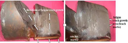
Figure 7. (a) The cup fracture sections of the broken quill shaft A after being cut-off into two pieces (continued). (b) Close up view of the surface fracture area, showing fatigue crack growth in two different directions. Under the splines area, the fatigue crack grew in a combined direction of transverse and radial, while outside the splines area the fatigue crack grew approximately 45° to the shaft axis and later turned in radial direction along the body shaft circumference to form a final typical cup fracture area
Metallurgical Assesment Of A Broken Gearbox Intermediate Shaft …../ D.n Adnyana | 23
grew in transverse and radial direction away from the splines until it reached the bolt hole. The second crack path started from a stress concentrated area formed between the spline tooth root and the groove, and subsequently grew across the groove and the shaft body in radial direction to form a radial “whirlpool” crack pattern on the shaft body circumference before a final cup like fracture occurred.
B. Macroscopic Examination and Analysis
Sequence of crack path formation in the broken quill shaft A may be well understood by viewing some illustration shown in Figure 8 in which its fracture surface topography is presented in Fig. 9. A closer view on the fracture surface shown in Fig. 9 confirmed that the broken quill shaft A has been experiencing fatigue fracture that was originated from the tooth root of the splined shaft where a high stress concentration formed there, especially at both the tooth edge ends. As seen in Figs. 9 and 10 several ratchet marks are formed on both edge ends of the splines tooth indicating severe stresses were present. Formation of these ratchet marks also indicates that the crack initiated at that area was not related or caused by the presence of any defect or flaw, but this was mainly influenced by the geometric factor of the splines and/or the splines/groove connection. Further, it can also be seen from Fig. 9 that the fatigue crack growth which is indicated by beach marks formation show two different directions as has been described earlier. One fatigue crack growth formed in transverse and radial direction as soon as it left the crack initiation sites. The other fatigue crack growth which formed outside of the splines engagement area is in the radial direction approximately 45° to the shaft axis, and this is further supporting the previous description. As also seen in Figs. 9 and 10, most of the beach marks are seen smooth and fine. In addition, there are also seen some long ratchet marks extended across the fine and smooth beach marks area. Furthermore, there is seen one large curve of beach mark line to separate each fatigue crack growth area as seen in Figs. 9 and 10. This change in crack growth or beach marks pattern may have been associated with a load change imposed to the quill shaft as the compressor load change was made during its operation.
Figure 8. Cracks path direction and position located under the splines (the engagement) area and within the body shaft (outside the engagement area) observed from different views. Several crack steps were formed on the edge indicating of fatigue crack growth
Figure 9. Close up view of the fatigue fracture surface exhibits crack initiation sites along the spline root having with some ratchet marks of a highly stressed area and the crack propagation area indicated by beach marks formation. The final fracture area is not seen in this figure as it was formed on the other side of the body shaft within the cup fracture portion
Figure 10. Close up view of the surface fracture area, showing fatigue crack growth in two different directions. Under the splines (engagement) area, the fatigue crack grew in a combined direction of transverse and radial, while outside the splines (engagement) area the fatigue crack grew approximately 45° to the shaft axis and later turned in radial direction to form a “whirlpool” crack pattern along the body shaft circumference prior to form an overload final fracture typical of cup like shape
24 | Majalah Metalurgi, V 31.1.2016, ISSN 0126-3188/ 1-68
Close up views of fatigue fracture topography shown in Figs. 9 and 10 at different locations are given in Fig. 11, showing the fatigue crack initiation sites with several ratchet marks of severe stresses were present, and the fatigue crack propagation area having with some smooth and rough beach marks. The photographs shown in this figure (Fig. 11) is to confirm the previous photofractographs that in addition to ratchet marks which are usually formed at the fatigue crack initiation sites, there were also other rough ratchet marks that may have formed within the beach marks area indicating of severe stresses were present due probably to a significant load change occurred on the quill shaft as required by compressor operation for production purpose.
Figure12. In addition to the main fatigue crack, a number of secondary fatigue cracks were also formed on the other splines teeth. However, some of these secondary fatigue cracks did not always form along the spline tooth root, indicating there was some engagement problem occurred between the shaft splines and the mating coupling hub due probably to some misalignment and/or geometrical clearance problem
In addition to the main fatigue crack as described earlier, a number of secondary fatigue cracks were also formed on the other spline teeth of the broken quill shaft A as presented in Fig. 12. However, as it is obviously seen in Fig. 12 some of these secondary fatigue cracks did not form along the spline tooth root of the quill shaft. This
indicates that there may have been some contact engagement problem occurred between the shaft splines and the splines of the mating
coupling hub due probably to some
misalignment and/or geometric clearance problem.
From the results of macroscopic
examination obtained on the surface fracture of the broken quill shaft A as presented above, and by using Fig. 13 to interpret the results obtained, it can be concluded that the broken quill shaft A had been experiencing fatigue fracture under complex stresses condition of a combination of shear stress, bending stress and torsion stress. From the fatigue crack path observed, under the engagement area where the shaft splines were in contact with the splines of the coupling hub, the level of bending stress and shear stress was quite high compared to the torsion stress and therefore the fatigue crack grew in transverse and radial direction, and later the crack stopped at the bolt hole. For the splined shaft located outside the engagement area, the shear stress was no longer present, while the bending stress decreased and therefore the majority of stresses present there was the torsion stress. Consequently, the fatigue crack grew in radial direction to form a radial “whirlpool” fracture pattern prior to a cup like final fracture. According to Fig. 13, formation of this final fracture area is relatively larger in comparison with the cross sectional area of the splined shaft body, and therefore the broken quill shaft A is considered to have been experiencing fatigue fracture due to a high
nominal stress with a severe stress
concentration[2].
Metallurgical Assesment Of A Broken Gearbox Intermediate Shaft …../ D.n Adnyana | 25
C.Chemical Composition Analysis
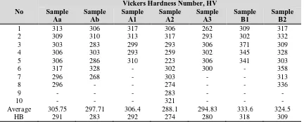
Two specimens were prepared for chemical composition analysis, one was sectioned from the broken quill shaft A and the other was sectioned from the unbroken quill shaft B at location close to the metallographic samples. The chemical analysis was carried out using an Optical Spark Emission Spectrometer. The results obtained are presented in Table 1 for the two samples A and B in comparison with the standard materials. It can be seen from Table 1 that the chemical compositions of both samples A and B are very much close and met the specimens were prepared from the unbroken quill shaft B. The tensile properties obtained such as yield strength, tensile strength and elongation are presented in Table 2 in comparison with the standard materials. It can be seen from Table 2 that except for the elongation, both tensile strength and yield strength of the unbroken quill shaft B are much lower than the tensile strength and yield strength of the standard material AISI 4340 in the as-normalized condition. The average tensile strength and yield strength of the
unbroken quill shaft B are 1044.0 MPa and 834.7 MPa, respectively, while for the standard material AISI 4340 in the as-normalized condition its tensile strength is 1280.0 MPa and its yield strength is 860 MPa. Similar situation is also obtained when comparison is made based on hardness test results as also presented in Table 2. The average hardness value obtained from specimens of the unbroken quill shaft B and the broken quill shaft A is 313.5 HB and 284.0 HB, respectively. Both of this hardness value is much lower compared to the hardness value of the standard material AISI 4340 in the as-normalized condition (363 HB). From the results of chemical composition analysis and tensile or hardness tests obtained it can be concluded that the material used for the
existing quill shaft met the material
specification AISI 4340 when it is compared to the chemical analysis, but its mechanical properties was not conformed with the material specification AISI 4340 in the as-normalized condition. The lower values of strength and hardness of the existing quill shaft material may have been influenced by inappropriate manufacturing and/or heat treating process provided to the shaft material. This low strength or hardness may have introduced the quill shaft material to be subjected into a high nominal stress condition during its operation, and therefore the quill shaft was susceptible to fatigue cracking. These tensile and hardness test results have further supported the previous test results obtained from the surface fracture analysis of the broken quill shaft A.
Figure 14. Drawing and dimension of tensile test specimen used in this failure analysis. The two tensile test specimens were made from the unbroken quill shaft B
Table 2 Results of tensile and hardness tests on the specimens obtained from the unbroken quill shaft B in comparison with the standard materials
Standard material AISI 4340 in normalized condition at 870 0
C 860.0 1280.0 12.2 363 Standard material AISI 4340 in annealed condition at 810 0C 475.0 745.0 22.0 217
Standard material AISI 4140 in normalized condition at 870 0
C 655.0 1020.0 17.7 302 Standard material AISI 4140 in annealed condition at 815 0
C 420.0 655.0 25.7 197 Note:
Ao = Initial cross sectional area
∆L = Total length increment Fy = Load at yield point Fm = Maximum load
YS = Yield Strength TS = Tensile Strength HB = Brinell Hardness Number
26 | Majalah Metalurgi, V 31.1.2016, ISSN 0126-3188/ 1-68
E. Metallographic Examination and
Analysis
Specimens for metallographic examination were obtained from the broken quill shaft A and from the unbroken quill shaft B, respectively. For the broken quill shaft A, the specimens were cut-off into two different locations, one was from the area with no surface fracture and the other was from the area with surface fracture. The area with no surface fracture was then sectioned in transverse and axial direction, respectively. For the unbroken quill shaft B, the specimens were only prepared in one area and then sectioned in transverse and axial direction to represent the splined shaft teeth and the shaft body.
Figure 15. Specimen preparation for metallographic examination obtained from some portion of the broken specimens obtained from the broken quill shaft A at location with no main fatigue surface fracture. Two specimens were made, one in transverse direction (sample Aa) and one in axial direction (sample Ab). It can be seen in Fig. 15 that both specimens exhibit secondary fatigue cracks that formed on some spline teeth. At higher magnifications, the cracks on a spline tooth and its corresponding microstructures are clearly seen (see Fig. 16). One crack is contact engagement between the shaft splines and the splines of the mating coupling hub was in bad condition and this was probably caused by some misalignment and/or geometric
clearance problem. The microstructures
obtained are a mixture of bainite or tempered As seen in Fig. 16, formation of the secondary fatigue cracks is transgranular in nature and
propagated mainly across the path where most of the ferrites are present. In addition, most of the microstructures obtained do not show any significant manufacturing defects or flaws such as inclusions or others.
Figure 16. Polished and etched specimen Aa, showing two secondary fatigue cracks formed on a spline tooth and the corresponding microstructures obtained from the cracked spline at tooth located around its root as indicated by
Other metallographic examinations on sample Aa were executed on two different areas to compare the microstructures difference between the spline tooth root and the internal part of the shaft splines, and the results obtained are presented in Figs. 17 and 18. The microstructures obtained are quite similar, consisting of a mixture of bainite or tempered martensite, fine pearlite and ferrite. No any significant difference in microstructures is found between the microstructures in the spline tooth root and in the internal part of the shaft splines. This indicates that the shaft splines have not been given any surface treatment or case hardening. The application of this surface treatment or case hardening on the splined shaft is considered necessary particularly for some heavy duty application to increase its fatigue effected by high stresses due to the application of splined shaft having with smaller pitch diameter than the shaft body diameter. For the results of metallographic examination on
specimen Ab, Fig. 20 shows the
Metallurgical Assesment Of A Broken Gearbox Intermediate Shaft …../ D.n Adnyana | 27
All microstructures obtained are similar to the microstructures obtained from sample Aa which consist of a mixture of bainite/ tempered martensite, fine pearlite and ferrite.
Figure 17. Microstructures obtained from sample Aa at a spline tooth root indicated by rectangular grid
Figure 18. Microstructures obtained from sample Aa at location indicated by rectangular grid
Figure 19. Polished and etched specimen Ab, showing some cracks formed on a spline tooth and on the shaft body internal fracture surface. It is also seen that the groove of this broken quill shaft A is a sharp square, without any radius applied. Beside that the splines pitch diameter is made less than the body shaft diameter
Figure 20. Microstructures obtained from sample Ab at a cracked spline tooth indicated by rectangular grid
Figure 21. Microstructures obtained from sample Ab at an area located in the shaft body internal fracture surface indicated by rectangular grid
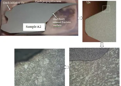
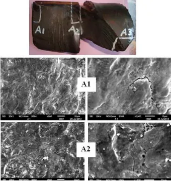
Preparation of specimens obtained from the fatigue fracture area of the broken quill shaft A is shown in Fig. 22. Three specimens were made in transverse direction from three different fracture locations, namely sample A1 at location around the fatigue crack initiation site and propagation area, sample A2 at location around the other fatigue crack initiation site between the spline tooth/groove section and its propagation area, and sample A3 at location around the final fracture area of the cup like fracture. For specimen A1, its microstructures are presented in Figs. 23 and
24. All microstructures obtained are similar in all locations either in the fatigue crack initiation site, in the fatigue crack propagation area, in area around the splines teeth, or in the internal
part of the spline body shaft. The
microstructures obtained are a mixture of bainite or tempered martensite, fine pearlite and ferrite. Most of the microstructures obtained from sample A2 in most locations are similar with those obtained from sample A1 containing a mixture of bainite or tempered martensite, fine pearlite and ferrite (see Figs. 25 to 28). The only difference was found at location around the final fracture area (see Fig. 27) in which the microstructures experienced some plastic deformation due to surface rubbing effect that may have occurred during the final fracture process of the quill shaft A.
Figure 22. Preparation of specimens obtained from the fatigue fracture area of the broken quill shaft A at three different locations (A1, A2, and A3)
Figure 23. Microstructures obtained from sample A1 at fatigue crack initiation site indicated by rectangular grid
Figure 24. Microstructures obtained from sample A1 at location indicated by rectangular grid
28 | Majalah Metalurgi, V 31.1.2016, ISSN 0126-3188/ 1-68 Figure 26. Microstructures obtained from sample A2 at
location around the fatigue crack propagation area indicated by rectangular grid
Figure 27. Microstructures obtained from sample A2 at location around the shaft body final fracture area indicated by rectangular grid
Figure 28. Microstructures obtained from sample A2 at location around the shaft body internal fracture surface indicated by rectangular grid. In this area, no any plastic deformation is observed, indicating that this area was still within the fatigue crack growth area
Microstructures obtained from sample A3 at locations around the final fracture area of the shaft body internal fracture surface are not presented in this paper. In these locations however, the metal surface was probably subjected to a high friction due to some rubbing effect occurred and this may have generated a very high temperature there.
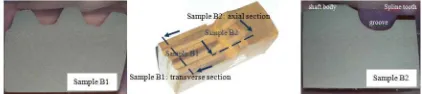
Preparation of specimens obtained from the section of the unbroken quill shaft B is presented in Fig. 29. Two specimens were prepared, one in transverse direction (sample B1) and one in axial direction (sample B2). The microstructures obtained from sample B1 at different locations are exhibited in Figs. 30 and 31. All microstructures obtained are similar with the microstructures obtained from the previous metallographic examinations either around the tooth root of the splines, on the spline tooth top, or in the splined shaft body
which always containing some mixture of bainite or tempered martensite, fine pearlite and ferrite.
Figure 29. Preparation of specimens obtained from the section of the unbroken quill shaft B. The specimens were prepared in transverse direction (sample B1) and in axial direction (sample B2), respectively
Figure 30. Microstructures obtained from sample B1 located around the spline tooth as indicated by rectangular grid
Figure 31. Microstructures obtained from sample B1 at location indicated by rectangular grid
Figure 32. Microstructures obtained from sample B2 at location around the groove as indicated by rectangular grid
Figure 33. Microstructures obtained from sample B2 at location around the shaft body as indicated by rectangular grid
Metallurgical Assesment Of A Broken Gearbox Intermediate Shaft …../ D.n Adnyana | 29
and the internal spline body, the
microstructures obtained in this sample B2 further confirm that the splines of the unbroken quill shaft B has not been given any surface treatment or case hardening process. The application of such surface treatment to the splined shaft is considered very useful to increase the fatigue strength of the quill shaft
significantly[3]. Furthermore, the
microstructures obtained in samples B1 and B2 obviously do not exhibit any significant defects that may have contributed to the acceleration of the quill shaft failure.
F. Hardness Test and Analysis
A hardness survey was carried out on all specimens at different test locations using the
same specimens for metallographic
examination. This hardness test was performed using Vickers method at a load of 5 kg (HV5). The hardness test results obtained are given in Table 3. Table 3 presents the hardness test results obtained from samples Aa and Ab of the broken quill shaft A. Samples Aa and Ab were obtained from the splined shaft section with no main fatigue fracture. From Table 3 it can be metallographic examination that the splined quill shaft A has not been given any surface treatment or case hardening to increase its surface hardness. It can also be seen from Table 3 that the average hardness value obtained from sample Aa is 305.75 HV or equivalent to 291 HB, whereas the average hardness value obtained from sample Ab is 297.71 HV or equivalent to 283 HB. From this average hardness value obtained it can be concluded that the hardness as well as the tensile strength of the quill shaft material A apparently did not meet the material specification AISI 4340 in its normalized condition (see also Tables 1 and 2). This also indicated that the quill shaft material A has not been subjected to a proper manufacturing or heat treatment process. The application of surface treatment on the splined shaft is therefore very important to further increase the level of its surface hardness that may improve its fatigue strength significantly.
From Table 3, it can also be seen the hardness test results obtained from the internal part of the splined shaft body for both broken quill shaft A (sample A1 to A3) and the
unbroken quill shaft B (sample B1 and B2). Variation in hardness among different test locations in each sample is about close to each other indicating that the shaft splines for quill quill shafts A and B have not been subjected to a proper manufacturing or heat treating process. From the aforementioned results and discussion, most likely the hardness or tensile concentration was present. For material specification AISI 4340 containing about 0.40 wt % carbon, the hardness level could be increased to reach a minimum hardness of 382 HV or 363 HB by performing a good manufacturing and/or heat treating process to obtain a complete microstructure of bainite and/or tempered martensite without any formation of ferrite or pearlite[4]. The presence of this ferrite and/or pearlite may have reduced the strength or hardness of the shaft material significantly. In addition, the application of surface treatment or case hardening is therefore very useful, particularly on the shaft splines where a high stress concentration is present.
30 | Majalah Metalurgi, V 31.1.2016, ISSN 0126-3188/ 1-68
the crack initiation site near to the edge end of the spline tooth, and its SEM micrographs obtained are presented in Fig. 34, showing the fatigue crack direction from lower left to the upper right. Fatigue striations were not resolvable at any location, and the entire fatigue
fracture surface displayed similar
crystallographic features. Not all metals form distinct striation in fatigue, and those that do may not form striations under all stress ranges depending on material and loading conditions (as well as condition of the fracture surface)[4]. However, the absence of striations may not mean that fatigue did not occur. Further evidence of the occurrence of fatigue fracture was also indicated by the fact that no any plastic deformation in the form of dimple fracture was observed on most of the SEM microfractographs shown in Fig. 34.
The corresponding EDS spectrum obtained from fatigue crack propagation area/crack initiation site are presented in Figs. 35 and 36. The EDS spectrum show some major elements of the low-alloy steel from which the broken quill shaft A was made such as: Fe, C, Ni, Cr, Mo, Si and Al. In addition, other significant elements were also present on most of the EDS spectrum such as C and O. The high C content found was not to represent the real carbon content of the fracture surface deposit, but this was very much influenced by the sample preparation or the specimen holder, whereas the high O content observed may be related to the oxide scales that may have formed on the fracture surface. It is also clearly seen from Figs. 35 and 36 that no any corroding element was present on most of the fracture surface deposit of the broken quill shaft A around its initial fatigue crack/fatigue propagation area.
Figure 34. SEM microfractographs obtained from fracture surface of the broken quill shaft A around the fatigue crack initiation sites A1 and A2, respectively
Figure 35. EDS spectrum of elements representing the corresponding composition of fracture surface at the broken quill shaft A at location around the fatigue crack initiation site A1
Figure 36. EDS spectrum of elements representing the corresponding composition of fracture surface at the broken quill shaft A at location around the fatigue crack initiation site A2
4.
C
ONCLUSIONSFrom the results of metallurgical assessment obtained, a number of conclusions can be drawn as follows:
The results of chemical analysis obtained show that the material used for the quill (intermediate) shaft is very much close and met to the material specification of AISI 4340. However, from the results of tensile and hardness tests obtained, the material used apparently do not meet to the material specification AISI 4340 in the as-normalized condition. The low tensile strength and hardness of the quill shaft material in comparison with the standard material was very much influenced by its microstructures which contained a mixture of bainite or tempered martensite, pearlite, and ferrite. The presence of
pearlite and especially ferrite in the
Metallurgical Assesment Of A Broken Gearbox Intermediate Shaft …../ D.n Adnyana | 31
properties quite significantly. Based on the above mentioned condition, it is most likely that the quill shaft material had not been subjected to a proper manufacturing and/or heat treating processes. From the microstructures and hardness test results obtained it was also found that the splines of the quill shaft material has not been given any surface treatment or case hardening, although this surface treatment is obviously very useful in improving its service life especially against any fatigue cracking.
According to the fracture topography and mode of failure, the broken quill shaft has been experiencing fatigue fracture that was caused by a combination of stresses of shear stress, bending stress and torsional stress. The fatigue fracture was initiated from the tooth root of the shaft splines and propagated into two directions. Under the contact engagement between the shaft splines and the coupling hub splines, due to the level of shear stress and bending stress was quite higher than the torsional stress, the fatigue crack propagated anticlockwise in transverse and radial direction. For the splines shaft located outside of the contact engagement area, due to no shear stress was present and the level of bending stress decreased, then the fatigue crack propagation was predominantly affected by the torsional stress. Therefore, the fatigue path turned into an anticlockwise direction approximately 450 to the shaft axis. As the bending stress continued to decrease, the fatigue crack direction also changed and formed a radial “whirlpool” crack pattern prior to the fast growing final fracture to form cup and cone like fractures. It was also found that the final fracture zone of the radial “whirlpool” cup like fracture of the broken quill shaft was relatively larger than the crack propagation zone in that particular area. This indicated that the fatigue fracture pattern of the broken quill shaft was produced by a high
nominal stress with a severe stress
concentration.
The fatigue fracture due to high nominal stresses experienced by the quill shaft during its operation may have been caused by the low strength of the material used for the quill shaft and/or due to some severe load cycling conditions were subjected to the compressor during its operation. In addition, the fatigue fracture was also affected by severe stress concentration experienced by the quill shaft caused by several factors that may have cooperated one to the other, such as: design or geometric factor of the splines including the
pitch diameter of the splines which was always made smaller than the shaft body diameter, the sharp corner or edges of the teeth, as well as the sharp edges of the teeth/groove section. Moreover, the length of the spline teeth was likely a little bit short and this may have also influenced to the high stress concentration present in the splines. A number of secondary fatigue cracks were also formed on the other spline teeth of the broken quill shaft. However, these secondary fatigue cracks did not always form along the spline tooth root, indicating that the shaft splines did not make any good contact engagement with the coupling hub splines due probably to some misalignment and/or some geometric clearance problem and shifted the stress concentration from its position.
Other test results also confirmed that corrosion may have not contributed to the acceleration of the quill shaft failure. In addition, other interesting evidence was also found that the end plate bolt hole was apparently acting as a fatigue crack stopper.
A
CKNOWLEDGEMENTSThe author wishes to express his gratitude to the members of the Department of Mechanical Engineering, Faculty of Industrial Technology of the National Institute of Science and Technology (ISTN) for their support and encouragement in publishing this work.
R
EFERENCES[1] A. Singhal and R.K. Mandloi, “Failure
Analysis of Automotive FWD Flexible
Drive Shaft-A Review,” International
Journal of Engineering Research and Applications (IJERA)., vol.3, issue 1, pp. 577-580, 2013.
[2] A. Osman, “Fatigue Failure of a Rear Axle
Shaft of an Automobile,” Engineering
Failure Analysis., vol. 13, pp. 1293-1302, 2006.
[3] M. Godec, D. Mandrino and M. Jenko,
“Investigation of the Fracture of a Car’s
Drive Shaft,” Engineering Failure
Analysis., vol. 16, pp. 1252-1261. 2009.
[4] A. Yadav, “Failure Analysis of Compressor
and Camshaft Gear-An Experimental
Approach,” International Journal of
Science., Engineering and Technology Research (IJSETR), vol. 1, issue 5, pp.