VI
Information
Management
Information Management is concerned with the collection, design, storage, organization, retrieval, and security of information in large databases. From a technology viewpoint, the emphasis is on the algorithms and structures underlying the databases. From an organi-zational viewpoint, the emphasis is on the relationship of information to business perfor-mance. Considerable research is also devoted to information management techniques that support the emerging global technological infrastructure. Particularly interesting here is the study of transaction processing in distributed computing environments, multimedia databases, and issues surrounding database security and privacy.
52 Data Models Avi Silberschatz, Henry F. Korth, and S. Sudarshan
Introduction • The Relational Model • Object-Based Models • XML • Further Reading
53 Tuning Database Design for High Performance Dennis Shasha and Philippe Bonnet
Introduction • Underlying Principles • Best Practices • Tuning the Application
Interface • Monitoring Tools • Tuning Rules of Thumb • Summary and Research Results
54 Access Methods Betty Salzberg and Donghui Zhang
Introduction • Underlying Principles • Best Practices • Research Issues and Summary
55 Query Optimization Yannis E. Ioannidis
Introduction • Query Optimizer Architecture • Algebraic Space • Planner • Size-Distribution Estimator • Noncentralized Environments • Advanced Types of Optimization • Summary
56 Concurrency Control and Recovery Michael J. Franklin
Introduction • Underlying Principles • Best Practices • Research Issues and Summary
57 Transaction Processing Alexander Thomasian
Introduction • Secure Distributed Transaction Processing: Cryptography • Transaction
Processing on the Web: Web Services • Concurrency Control for High-Contention
Environments • Performance Analysis of Transaction Processing Systems • Conclusion
58 Distributed and Parallel Database Systems M. TamerÖzsu and Patrick Valduriez
Introduction • Underlying Principles • Distributed and Parallel
59 Multimedia Databases: Analysis, Modeling, Querying, and Indexing Vincent Oria, Ying Li, and Chitra Dorai
Introduction • Image Content Analysis • Video Content Analysis • Bridging the
Semantic Gap in Content Management • Modeling and Querying Images • Modeling and
Querying Videos • Multidimensional Indexes for Image and Video Features • Multimedia
Query Processing • Emerging MPEG-7 as Content Description Standard • Conclusion
60 Database Security and Privacy Sushil Jajodia
52
Data Models
Avi Silberschatz
Yale University
Henry F. Korth
Lehigh University
S. Sudarshan
IIT Bombay
52.1 Introduction 52.2 The Relational Model
Formal Basis • SQL •Relational Database Design •History
52.3 Object-Based Models
The Entity-Relationship Model• Object-Oriented Model •Object-Relational Data Models
52.4 XML
52.5 Further Reading
52.1 Introduction
Underlying the structure of a database is the concept of adata model. A data model is a collection of conceptual tools for describing the real-world entities to be modeled in the database and the relationships among these entities. Data models differ in the primitives available for describing data and in the amount of semantic detail that can be expressed.
The various data models that have been proposed fall into three different groups: physical data models, record-based logical models, and object-based logical models. Physical data models are used to describe data at the lowest level. Physical data models capture aspects of database system implementation that are not covered in this article. Database system interfaces used by application programs are based on the logical data model; databases hide the underlying implementation details from applications.
This chapter focuses on logical data models, covering the relational data model, theE-Rmodel, the object-oriented and object-relational data models, andXML.
52.2 The Relational Model
Therelational modelis currently the primary data model for commercial data-processing applications. It has attained its primary position because of its simplicity, which eases the job of the programmer, as compared to earlier data models.
A relational database consists of a collection oftables, each of which is assigned a unique name. An instanceof a table storing customer information is shown inTable 52.1.The table has several rows, one for each customer, and several columns, each storing some information about the customer. The values in thecustomer-idcolumn of thecustomertable serve to uniquely identify customers, while other columns store information such as the name, street address, and city of the customer.
TABLE 52.1 TheCustomerTable
Customer-id Customer-Name Customer-Street Customer-City
019-28-3746 Smith North Rye
182-73-6091 Turner Putnam Stamford 192-83-7465 Johnson Alma Palo Alto
244-66-8800 Curry North Rye
321-12-3123 Jones Main Harrison 335-57-7991 Adams Spring Pittsfield 336-66-9999 Lindsay Park Pittsfield 677-89-9011 Hayes Main Harrison 963-96-3963 Williams Nassau Princeton
TABLE 52.2 TheLoanTable
Loan-Number Amount
L-11 900
L-14 1500
L-15 1500
L-16 1300
L-17 1000
L-23 2000
L-93 500
TABLE 52.3 TheBorrowerTable
Customer-id Loan-Number
019-28-3746 L-11 019-28-3746 L-23 244-66-8800 L-93 321-12-3123 L-17 335-57-7991 L-16 555-55-5555 L-14 677-89-9011 L-15 963-96-3963 L-17
In addition to information about “entities” such as customers or loans, there is also a need to store information about “relationships” between such entities. For example, the bank needs to track the re-lationship between customers and loans. Table 52.3 shows theborrowertable, which stores information indicating which customers have taken which loans. If several people have jointly taken a loan, the same loan number would appear several times in the table with different customer-ids (e.g., loan number L-17). Similarly, if a particular customer has taken multiple loans, there would be several rows in the table with the customer-id of that customer (e.g., 019-28-3746), with different loan numbers.
52.2.1 Formal Basis
At the user level, a relation is represented as a table. The table has one column for each domain and one row for each tuple. Each column has a name, which serves as a column header, and is called anattribute
of the relation. The list of attributes for a relation is called therelation schema. The terms “table” and “relation” are used synonymously, as are row and tuple, as also column and attribute.
Data models also permit the definition ofconstraintson the data stored in the database. For instance, key constraintsare defined as follows. If a set of attributesL is specified to be asuper-keyfor relationr, in any consistent (“legal”) database, the set of attributesL would uniquely identify a tuple inr; that is, no two tuples inr can have the same values for all attributes inL. For instance,customer-idwould form a super-key for relationcustomer. A relation can have more than one super-key, and usually one of the super-keys is chosen as aprimary key; this key must be a minimal set, that is, dropping any attribute from the set would make it cease to be a super-key.
Another form of constraint is theforeign keyconstraint, which specifies that for each tuple in one relation, there must exist a matching tuple in another relation. For example, a foreign key constraintfrom borrower referencing customerspecifies that for each tuple inborrower, there must be a tuple incustomer with a matchingcustomer-idvalue.
Users of a database system can query the data, insert new data, delete old data, or update the data in the database. Of these tasks, the task of querying the data is usually the most complicated. In the case of the relational data model, because data is stored as tables, a user can query these tables, insert new tuples, delete tuples, and update (modify) tuples. There are several languages for expressing these operations.
The tuple relational calculus and the domain relational calculus are nonprocedural languages that represent the basic power required in a relational query language. Both of these languages are based on statements written in mathematical logic. We omit details of these languages.
The relational algebra is a procedural query language that defines several operations, each of which takes one or more relations as input and returns a relation as output. For example:
r Theselectionoperation is used to get a subset of tuples from a relation, by specifying a predicate.
The selection operationP(r) returns the set of tuples ofrthat satisfy the predicateP.
r TheprojectionoperationL(r) is used to return a relation containing a specified set of attributes
L of a relationr, removing the other attributes ofr.
r Theunionoperationr∪sreturns the union of the tuples inrands. Theintersectionanddifference
operations are similarly defined.
r Thenatural joinoperation ⊲⊳ is used to combine information from two relations. For example,
the natural join of the relationsloanandborrower, denotedloan⊲⊳borrowerwould be the relation defined as follows. First match each tuple inloanwith each tuple inborrowerthat has the same values for the shared attributeloan-number; for each pair of matching tuples, the join operation creates a tuple containing all attributes from both tuples; the join result relation is the set of all such tuples.
For instance, the natural join of theloanandborrowertables in Tables 52.2 and 52.3 contains tuples (L-17, 1000, 321-12-3123) and (L-17, 1000, 963-96-3963), since the tuple with loan number L-17 in theloantable matches two different tuples with loan number L-17 in theborrowertable.
The relational algebra has other operations as well; for example, operations that can aggregate values from multiple tuples, for example by summing them up, or finding their average.
Because the result of a relational algebra operation is itself a relation, it can be used in further operations. As a result, complex expressions with multiple operations can be defined in the relational algebra.
Among the reasons for the success of the relational model are its basic simplicity, representing all data using just a single notion of tables, as well as its formal foundations in mathematical logic and algebra.
52.2.2 SQL
The SQLlanguage has clearly established itself asthestandard relational database language. The SQL language has a data definition component for specifying schemas, and a data manipulation component for querying data as well as for inserting, deleting, and updating data.
We illustrate some examples of queries and updates inSQL. The following query finds the name of the customer whosecustomer-idis 192-83-7465:
select customer.customer-name
from customer
where customer.customer-id=’192-83-7465’
Queries may involve information from more than one table. For example, the following query finds the amount of all loans owned by the customer with customer-id 019-28-3746:
select loan.loan-number, loan.amount
from borrower,loan
where borrower.customer-id=’019-28-3746’and
borrower.loan-number=loan.loan-number
If the above query were run on the tables shown earlier, the system would find that the loans L-11 and L-23 are owned by customer 019-28-3746, and would print out the amounts of the two loans, namely 900 and 2000.
The followingSQLstatement adds an interest of 5% to the loan amount of all loans with amounts greater than 1000.
update loan
set amount=amount* 1.05
where amount>10000
Over the years, there have been several revisions of theSQLstandard. The most recent isSQL:1999.QBE and Quel are two other significant query languages. Of these, Quel is no longer in widespread use, while QBEis used only in a few database systems such as Microsoft Access.
52.2.3 Relational Database Design
The process of designing a conceptual level schema for a relational database involves the selection of a set of relational schemas. There are several approaches to relational database design. One approach, which we describe inSection 52.3.1, is to create a model of the enterprise using a higher-level data model, such as the entity-relationship model, and then translate the higher-level model into a relational database design. Another approach is to directly create a design, consisting of a set of tables and a set of attributes for each table. There are often many possible choices that the database designer might make. A proper balance must be struck among three criteria for a good design:
1. Minimization of redundant data
2. Ability to represent all relevant relationships among data items
3. Ability to test efficiently the data dependencies that require certain attributes to be unique identifiers To illustrate these criteria for a good design, consider a database of employees, departments, and man-agers. Let us assume that a department has only one manager, but a manager may manage one or more departments. If we use a single relationemp-info1(employee, department, manager), then we must repeat the manager of a department once for each employee. Thus we haveredundantdata.
relevant relationships among data items using the decomposed relations; such a decomposition is called a lossy-join decomposition. If instead, we chose the two relations emp-dept(employee, department) and dept-mgr(department, manager), we would avoid this difficulty, and at the same time avoid redundancy. With this decomposition, joining the information in the two relations would give back the information in emp-info1; such a decomposition is called alossless-join decomposition.
There are several types of data dependencies. The most important of these arefunctional dependencies. A functional dependency is a constraint that the value of a tuple on one attribute or set of attributes determines its value on another. For example, the constraint that a department has only one manager could be stated as “department functionally determines manager.” Because functional dependencies represent facts about the enterprise being modeled, it is important that the system check newly inserted data to ensure no functional dependency is violated (as in the case of a second manager being inserted for some department). Such checks ensure that the update does not make the information in the database inconsistent. The cost of this check depends on the design of the database.
There is a formal theory of relational database design that allows us to construct designs that have minimal redundancy, consistent with meeting the requirements of representing all relevant relationships, and allowing efficient testing of functional dependencies. This theory specifies certain properties that a schema must satisfy, based on functional dependencies. For example, a database design is said to be in a Boyce-Codd normal formif it satisfies a certain specified set of properties; there are alternative specifications, for instance thethird normal form. The process of ensuring that a schema design is in a desired normal form is callednormalization.
More details can be found in standard textbooks on databases; Ullman [Ull88], provides a detailed coverage of database design theory.
52.2.4 History
The relational model was developed in the late 1960s and early 1970s by E.F. Codd. The 1970s saw the development of several experimental database systems based on the relational model and the emergence of a formal theory to support the design of relational databases. The commercial application of relational databases began in the late 1970s but was limited by the poor performance of early relational systems. During the 1980s numerous commercial relational systems with good performance became available. Simultaneously, simple database systems based loosely on the relational approach were introduced for single-user personal computers. In the latter part of the 1980s, efforts were made to integrate collections of personal computer databases with large mainframe databases.
The relational model has since established itself as the primary data model for commercial data pro-cessing applications. Earlier generation database systems were based on thenetwork data modelor the hierarchical data model. Those two older models are tied closely to the data structures underlying the imple-mentation of the database. We omit details of these models because they are now of historical interest only.
52.3 Object-Based Models
The relational model is the most widely used data model at the implementation level; most databases in use around the world are relational databases. However, the relational view of data is often too detailed for conceptual modeling. Data modelers need to work at a higher level of abstraction.
Object-based logical models are used in describing data at the conceptual level. The object-based models use the concepts ofentitiesorobjectsand relationships among them rather than the implementation-based concepts of the record-implementation-based models. They provide flexible structuring capabilities and allow data constraints to be specified explicitly. Several object-based models are in use; some of the more widely known ones are:
The entity-relationship model has gained acceptance in database design and is widely used in practice. The object-oriented model includes many of the concepts of the entity-relationship model, but represents executable code as well as data. The object-relational data model combines features of the object-oriented data model with the relational data model.
The semantic data model and the the functional data model are two other object-based data models; currently, they are not widely used.
52.3.1 The Entity-Relationship Model
TheE-Rdata model derives from the perception of the world or, more specifically, of a particular enterprise in the world, as consisting of a set of basic objects calledentities, andrelationshipsamong these objects. It facilitates database design by allowing the specification of anenterprise schema, which represents the overall logical structure of a database. TheE-Rdata model is one of several semantic data models; that is, it attempts to represent the meaning of the data.
52.3.1.1 Basics
There are three basic notions that theE-Rdata model employs: entity sets, relationship sets, and attributes. Anentityis a “thing” or “object” in the real world that is distinguishable from all other objects. For example, each person in the universe is an entity.
Each entity is described by a collection of features, calledattributes. For example, the attributes account-numberandbalancemay describe one particular account in a bank, and they form attributes of theaccount entity set. Similarly, attributescustomer-name,customer-streetaddress andcustomer-citymay describe a customerentity.
The values for some attributes may uniquely identify an entity. For example, the attributecustomer-id may be used to uniquely identify customers (because it may be possible to have two customers with the same name, street address, and city). A unique customer identifier must be assigned to each customer. In the United States, many enterprises use the social-security number of a person (a unique number the U.S. Government assigns to every person in the United States) as a customer identifier.
An entity may be concrete, such as a person or a book, or it may be abstract, such as a bank account, a holiday, or a concept.
Anentity setis a set of entities of the same type that share the same properties (attributes). The set of all persons working at a bank, for example, can be defined as the entity setemployee, and the entity John Smith may be a member of theemployeeentity set. Similarly, the entity setaccountmight represent the set of all accounts in a particular bank. A database thus includes a collection of entity sets, each of which contains any number of entities of the same type.
Attributes are descriptive properties possessed by all members of an entity set. The designation of attributes expresses that the database stores similar information concerning each entity in an entity set; however, each entity has its own value for each attribute. Possible attributes of theemployeeentity set are employee-name,employee-id, andemployee-address. Possible attributes of theaccountentity set are account-numberandaccount-balance. For each attribute there is a set of permitted values, called thedomain(or value set) of that attribute. The domain of the attributeemployee-namemight be the set of all text strings of a certain length. Similarly, the domain of attributeaccount-numbermight be the set of all positive integers. Entities in an entity set are distinguished based on their attribute values. A set of attributes that suffices to distinguish all entities in an entity set is chosen, and called aprimary keyof the entity set. For the employeeentity set, employee-idcould serve as a primary key; the enterprise must ensure that no two people in the enterprise can have the same employee identifier.
FIGURE 52.1 E-Rdiagram.
accountentity sets. We could associate an attributelast-accessto specify the date of the most recent access to the account. The relationship setsemp-deptanddepositorare examples of a binary relationship set, that is, one that involves two entity sets. Most of the relationship sets in a database system are binary.
The overall logical structure of a database can be expressed graphically by anE-Rdiagram. Such a diagram consists of the following major components:
r Rectangles, which represent entity sets r Ellipses, which represent attributes
r Diamonds, which represent relationship sets
r Lines, which link entity sets to relationship sets, and link attributes to both entity sets and
relation-ship sets
An entity-relationship diagram for a portion of our simple banking example is shown inFigure 52.1.The primary key attributes (if any) of an entity set are shown underlined.
Composite attributesare attributes that can be divided into subparts (that is, other attributes). For example, an attributenamecould be structured as a composite attribute consisting offirst-name, middle-initial, andlast-name. Using composite attributes in a design schema is a good choice if a user wishes to refer to an entire attribute on some occasions, and to only a component of the attribute on other occasions. The attributes in our examples so far all have a single value for a particular entity. For instance, the loan-numberattribute for a specific loan entity refers to only one loan number. Such attributes are said to besingle valued. There may be instances where an attribute has a set of values for a specific entity. Consider anemployeeentity set with the attributephone-number. An employee may have zero, one, or several phone numbers, and hence this type of attribute is said to bemultivalued.
Suppose that thecustomerentity set has an attributeagethat indicates the customer’s age. If thecustomer entity set also has an attributedate-of-birth, we can calculateagefromdate-of-birthand the current date. Thus,ageis aderived attribute. The value of a derived attribute is not stored, but is computed when required.
Figure 52.2shows how composite, multivalued, and derived attributes can be represented in theE-R notation. Ellipses are used to represent composite attributes as well as their subparts, with lines connecting the ellipse representing the attribute to the ellipse representing its subparts. Multivalued attributes are represented using a double ellipse, while derived attributes are represented using a dashed ellipse.
FIGURE 52.2 E-Rdiagram with composite, multivalued, and derived attributes.
FIGURE 52.3 E-Rdiagram with role indicators.
Consider, for example, a relationship set works-forrelating the entity setemployee with itself. Each employee entity is related to the entity representing the manager of the employee. One employee takes on the role ofworker, whereas the second takes on the role ofmanager. Roles can be depicted inE-Rdiagrams as shown in Figure 52.3.
Although the basicE-Rconcepts can model most database features, some aspects of a database may be more aptly expressed by certain extensions to the basicE-Rmodel. Commonly used extendedE-R features include specialization, generalization, higher- and lower-level entity sets, attribute inheritance, and aggregation. The notion of specialization and generalization are covered in the context of object-oriented data models inSection 52.3.2. A full explanation of the other features is beyond the scope of this chapter; we refer readers to the references listed at the end of this chapter for additional information. 52.3.1.2 Representing Data Constraints
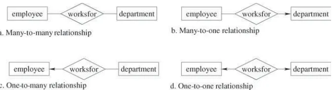
FIGURE 52.4 Relationship cardinalities.
FIGURE 52.5 Cardinality limits on relationship sets.
and an employee was required to work for exactly one department. In an E-R diagram, an arrow is used to indicate the type of relationship, as shown in Figure 52.4.
E-Rdiagrams also provide a way to indicate more complex constraints on the number of times each entity participates in relationships in a relationship set. An edge between an entity set and a binary relationship set can have an associated minimum and maximum cardinality, shown in the forml..h, wherel is the minimum andhthe maximum cardinality. A maximum value of 1 indicates that the entity participates in at most one relationship, while a maximum value∗indicates no limit.
For example, consider Figure 52.5. The edge betweenloanandborrowerhas a cardinality constraint of 1..1, meaning the minimum and the maximum cardinality are both 1. That is, each loan must have exactly one associated customer. The limit 0..∗on the edge fromcustomertoborrowerindicates that a customer can have zero or more loans. Thus, the relationshipborroweris one to many fromcustomertoloan.
It is easy to misinterpret the 0..∗on the edge betweencustomerandborrower, and think that the relation-shipborroweris many-to-one fromcustomertoloan— this is exactly the reverse of the correct interpretation. If both edges from a binary relationship have a maximum value of 1, the relationship is one-to-one. If we had specified a cardinality limit of 1..∗on the edge betweencustomerandborrower, we would be saying that each customer must have at least one loan.
52.3.1.3 Use of E-R Model in Database Design
A high-level data model, such as theE-Rmodel, serves the database designer by providing a conceptual framework in which to specify, in a systematic fashion, the data requirements of the database users and how the database will be structured to fulfill these requirements. The initial phase of database design, then, is to fully characterize the data needs of the prospective database users. The outcome of this phase will be a specification of user requirements. The initial specification of user requirements may be based on interviews with the database users, and the designer’s own analysis of the enterprise. The description that arises from this design phase serves as the basis for specifying the logical structure of the database.
enterprise. Stated in terms of theE-Rmodel, the conceptual schema specifies all entity sets, relationship sets, attributes, and mapping constraints. The schema can be reviewed to confirm that all data requirements are indeed satisfied and are not in conflict with each other. The design can also be examined to remove any redundant features. The focus at this point is on describing the data and its relationships, rather than on physical storage details.
A fully developed conceptual schema also indicates the functional requirements of the enterprise. In a specification of functional requirements, users describe the kinds of operations (or transactions) that will be performed on the data. Example operations include modifying or updating data, searching for and retrieving specific data, and deleting data. A review of the schema for meeting functional requirements can be made at the conceptual design stage.
The process of moving from a conceptual schema to the actual implementation of the database involves two final design phases. Although these final phases extend beyond the role of data models, we present a brief description of the final mapping from model to physical implementation. In thelogical design
phase, the high-level conceptual schema is mapped onto the implementation data model of the database management system (DBMS). The resultingDBMS-specific database schema is then used in the subsequent
physical designphase, in which the physical features of the database are specified. These features include the form of file organization and the internal storage structures.
Because theE-Rmodel is extremely useful in mapping the meanings and interactions of real-world enterprises onto a conceptual schema, a number of database design tools draw onE-Rconcepts. Further, the relative simplicity and pictorial clarity of theE-Rdiagramming technique may well account, in large part, for the widespread use of theE-Rmodel.
52.3.1.4 Deriving a Relational Database Design from the E-R Model
A database that conforms to anE-Rdiagram can be represented by a collection of tables. For each entity set and each relationship set in the database, there is a unique table that is assigned the name of the corresponding entity set or relationship set. Each table has a number of columns that, again, have unique names. The conversion of database representation from anE-Rdiagram to a table format is the basis for deriving a relational database design.
The column headers of a table representing an entity set correspond to the attributes of the entity, and the primary key of the entity becomes the primary key of the relation. The column headers of a table repre-senting a relationship set correspond to the primary key attributes of the participating entity sets, and the attributes of the relationship set. Rows in the table can be uniquely identified by the combined primary keys of the participating entity sets. For such a table, the primary keys of the participating entity sets areforeign keysof the table. The rows of the tables correspond to individual members of the entity or relationship set. Table 52.1throughTable 52.3show instances of tables that correspond, respectively, to thecustomerand loanentity sets, theborrowerrelationship set, ofFigure 52.5.
52.3.2 Object-Oriented Model
The object-oriented data model is an adaptation of the object-oriented programming paradigm to database systems. The object-oriented approach to programming was first introduced by the language Simula 67, which was designed for programming simulations. More recently, the languages Smalltalk, C++, and Java have become the most widely known object-oriented programming languages. Database applications in such areas as computer-aided design and bio-informatics do not fit the set of assumptions made for older, data-processing-style applications. The object-oriented data model has been proposed to deal with some of these applications. The model is based on the concept of encapsulating data, and code that operates on that data, in an object.
52.3.2.1 Basics
the object. The value stored in an instance variable may itself be an object. Objects can contain objects to an arbitrarily deep level of nesting. At the bottom of this hierarchy are objects such as integers, character strings, and other data types that are built into the object-oriented system and serve as the foundation of the object-oriented model. The set of built-in object types varies from system to system.
In addition to representing data, objects have the ability to initiate operations. An object may send a messageto another object, causing that object to execute amethodin response. Methods are procedures, written in a general-purpose programming language, that manipulate the object’s local instance variables and send messages to other objects. Messages provide the only means by which an object can be accessed. Therefore, the internal representation of an object’s data need not influence the implementation of any other object. Different objects may respond differently to the same message. This encapsulation of code and data has proven useful in developing higher modular systems. It corresponds to the programming language concept of abstract data types.
The only way in which one object can access the data of another object is by invoking a method of that other object. This is calledsending a messageto the object. Thus, the call interface of the methods of an object defines its externally visible part. The internal part of the object — the instance variables and method code — are not visible externally. The result is two levels of data abstraction.
To illustrate the concept, consider an object representing a bank account. Such an object contains instance variablesaccount-numberandaccount-balance, representing the account number and account balance. It contains a methodpay-interest, which adds interest to the balance. Assume that the bank had been paying 4% interest on all accounts but now is changing its policy to pay 3% if the balance is less than $1000 or 4% if the balance is $1000 or greater. Under most data models, this would involve changing code in one or more application programs. Under the object-oriented model, the only change is made within thepay-interestmethod. The external interface to the object remains unchanged.
52.3.2.2 Classes
Objects that contain the same types of values and the same methods are grouped together intoclasses. A class may be viewed as a type definition for objects. This combination of data and code into a type definition is similar to the programming language concept of abstract data types. Thus, allemployeeobjects may be grouped into an employeeclass. Classes themselves can be grouped into a hierarchy of classes; for example, theemployeeclass and thecustomerclasses may be grouped into apersonclass. The classpersonis asuperclassof theemployeeandcustomerclasses because all objects of theemployeeandcustomerclasses also belong to thepersonclass. Superclasses are also calledgeneralizations. Correspondingly, theemployee andcustomerclasses aresubclassesofperson; subclasses are also calledspecializations.
The hierarchy of classes allows sharing of common methods. It also allows several distinct views of objects: an employee, for an example, may be viewed either in the role of person or employee, whichever is more appropriate.
52.3.2.3 The Unified Modeling Language UML
TheUnified Modeling Language(UML) is a standard for creating specifications of various components of a software system. Some of the parts ofUMLare:
r Class diagram. Class diagrams play the same role asE-Rdiagrams, and are used to model data. Later
in this section we illustrate a few features of class diagrams and how they relate toE-Rdiagrams.
r Use case diagram. Use case diagrams show the interaction between users and the system, in
par-ticular the steps of tasks that users perform (such as withdrawing money or registering for a course).
r Activity diagram. Activity diagrams depict the flow of tasks between various components of a
system.
r Implementation diagram. Implementation diagrams show the system components and their
We do not attempt to provide detailed coverage of the different parts ofUMLhere; we only provide some examples illustrating key features ofUMLclass diagrams. See the bibliographic notes for references on UMLfor more information.
UMLclass diagrams model objects, whereasE-Rmodels entities. Objects are similar to entities, and have attributes, but additionally provide a set of functions (called methods) that can be invoked to compute values on the basis of attributes of the objects, or to update the object itself. Class diagrams can depict methods in addition to attributes.
We represent binary relationship sets inUMLby drawing a line connecting the entity sets. We write the relationship set name adjacent to the line. We may also specify the role played by an entity set in a relationship set by writing the role name on the line adjacent to the entity set. Alternatively, we may write the relationship set name in a box, along with attributes of the relationship set, and connect the box by a dotted line to the line depicting the relationship set. This box can then be treated as an entity set, in the same way as an aggregation inE-Rdiagrams and can participate in relationships with other entity sets.UML1.3 supports non-binary relationships, using the same diamond notation used inE-R diagrams.
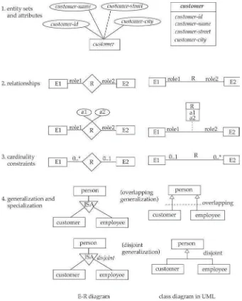
Cardinality constraints are specified inUMLin the same way as inE-Rdiagrams, in the forml..h, wherel denotes the minimum andhthe maximum number of relationships an entity can participate in. However, the interpretation here is that the constraint indicates the minimum/maximum number of relationships an object can participate in,given that the other object in the relationship is fixed. You should be aware that, as a result, the positioning of the constraints is exactly the reverse of the positioning of constraints inE-Rdiagrams, as shown inFigure 52.6. The constraint 0..∗on theE2 side and 0..1 on the E1 side means that eachE2 entity can participate in, at most, one relationship, whereas eachE1 entity can participate in many relationships; in other words, the relationship is many-to-one fromE2 to E1.
Single values such as 1 or∗may be written on edges; the single value 1 on an edge is treated as equivalent to 1..1, while∗is equivalent to 0..∗.
We represent generalization and specialization inUMLby connecting entity sets by a line with a triangle at the end corresponding to the more general entity set. For instance, the entity setpersonis a generalization of customerandemployee.UMLdiagrams can also represent explicitly the constraints of disjoint/overlapping on generalizations. For instance, if thecustomer/employee-to-persongeneralization is disjoint, it means that no one can be both acustomerand anemployee. An overlapping generalization allows a person to be both acustomerand anemployee. Figure 52.6 shows how to represent disjoint and overlapping generalizations ofcustomerandemployeetoperson.
52.3.2.4 Object-Oriented Database Programming Languages
There are two approaches to creating an object-oriented database language: the concepts of object orien-tation can be added to existing database languages, or existing object-oriented languages can be extended to deal with databases by adding concepts such as persistence and collections. Object-relational database systems take the former approach. Persistent programming languages follow the latter approach.
Persistent extensions to C++ and Java have made significant technical progress in the past decade. Several object-oriented database systems succeeded in integrating persistence fairly seamlessly and orthogonally with existing language constructs. The Object Data Management Group (ODMG) developed standards for integrating persistence support into several programming languages such as Smalltalk, C++, and Java. However, object-oriented databases based on persistent programming languages have faced significant hurdles in commercial adoption, in part because of their lack of support for legacy applications, and in part because the features provided by object-oriented databases did not make a significant different to typical data processing applications.
FIGURE 52.6 Correspondence of symbols used in theE-Rdiagram andUMLclass diagram notation.
52.3.3 Object-Relational Data Models
Object-relational data models extend the relational data model by providing a richer type system including object orientation. Constructs are added to relational query languages such asSQLto deal with the added data types. The extended type systems allow attributes of tuples to have complex types, including non-atomic values such as nested relations. Such extensions attempt to preserve the relational foundations, in particular the declarative access to data, while extending the modeling power.
each tuple in a lower-level relation must correspond to a unique tuple in a higher-level relation that repre-sents information about the same object. Inheritance of relations provides a convenient way of modeling roles, where an object can acquire and relinquish roles over a period of time.
Several object-oriented extensions toSQLhave been proposed in the recent past. TheSQL:1999standard supports a variety of object-oriented features, including complex data types such as records and arrays, and type hierarchies with classes and subclasses. Values of attributes can be of complex types. Objects, however, do not have an independent existence; they correspond to tuples in a relation.SQL:1999also supports references to objects; references must be to objects of a particular type, which are stored as tuples of a particular relation.
SQL:1999supports table inheritance; ifr is a subtable ofs, the type of tuples ofr must be a subtype of the type of tuples ofs. Every tuple present inr is implicitly (automatically) present ins as well. A query ons would find all tuples inserted directly tosas well as tuples inserted intor; however, only the attributes of tableswould be accessible, even for ther tuples. Thus, subtables can be used to represent specialization/generalization hierarchies. However, while subtables in theSQL:1999standard can be used to represent disjoint specializations, where an object cannot belong to two different subclasses of a particular class, they cannot be used to represent the general case of overlapping specialization.
In addition to object-oriented data-modeling features,SQL:1999supports an imperative extension of theSQLquery language, providing features such asforandwhileloops,if-then-elsestatements, procedures, and functions.
52.4 XML
Unlike most of the data models, theExtensible Markup Language(XML) was not originally conceived as a database technology. In fact, like theHyper-Text Markup Language(HTML) on which the World Wide Web is based,XMLhas its roots in document management. However, unlikeHTML,XMLcan represent database data, as well as many other kinds of structured data used in business applications. It is particularly useful as a data format when an application must communicate with another application, or integrate information from several other applications.
The termmarkupin the context of documents refers to anything in a document that is not intended to be part of the printed output. For the family of markup languages that includesHTMLandXML, the markup takes the form oftagsenclosed in angle-brackets,<>. Tags are used in pairs, with<tag>and </tag>delimiting the beginning and the end of the portion of the document to which the tag refers. For example, the title of a document might be marked up as follows:
<title>Database System Concepts</title>
UnlikeHTML,XMLdoes not prescribe the set of tags allowed, and the set may be specialized as needed. This feature is the key toXML’s major role in data representation and exchange, whereasHTMLis used primarily for document formatting.
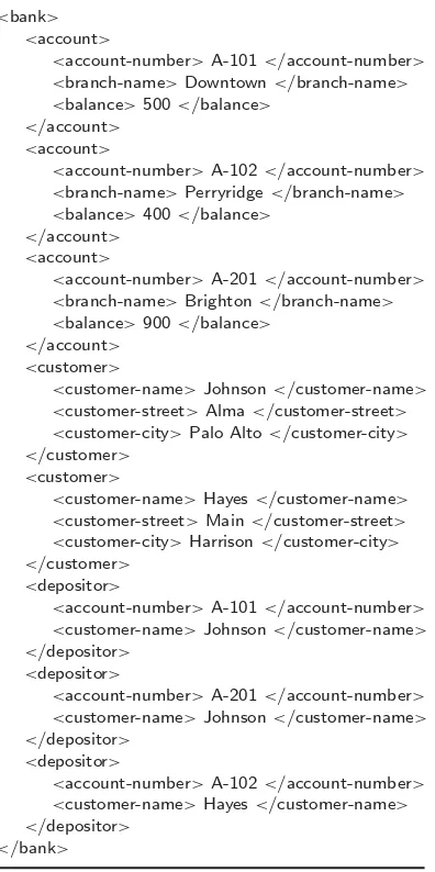
For example, in our running banking application, account and customer information can be represented as part of anXMLdocument as inTable 52.4. Observe the use of tags such asaccountandaccount-number. These tags provide context for each value and allow the semantics of the value to be identified. The contents between a start tag and its corresponding end tag is called anelement.
Compared to storage of data in a database, theXMLrepresentation may be inefficient because tag names are repeated throughout the document. However, despite this disadvantage, anXMLrepresentation has significant advantages when it is used to exchange data, for example, as part of a message:
r The presence of the tags makes the messageself-documenting; that is, a schema need not be
con-sulted to understand the meaning of the text. We can readily read the fragment above, for example.
r The format of the document is not rigid. For example, if some sender adds additional information,
TABLE 52.4 XMLRepresentation of Bank Information
<bank> <account>
<account-number>A-101</account-number> <branch-name>Downtown</branch-name> <balance>500</balance>
</account> <account>
<account-number>A-102</account-number> <branch-name>Perryridge</branch-name> <balance>400</balance>
</account> <account>
<account-number>A-201</account-number> <branch-name>Brighton</branch-name> <balance>900</balance>
</account> <customer>
<customer-name>Johnson</customer-name> <customer-street>Alma</customer-street> <customer-city>Palo Alto</customer-city> </customer>
<customer>
<customer-name>Hayes</customer-name> <customer-street>Main</customer-street> <customer-city>Harrison</customer-city> </customer>
<depositor>
<account-number>A-101</account-number> <customer-name>Johnson</customer-name> </depositor>
<depositor>
<account-number>A-201</account-number> <customer-name>Johnson</customer-name> </depositor>
<depositor>
<account-number>A-102</account-number> <customer-name>Hayes</customer-name> </depositor>
</bank>
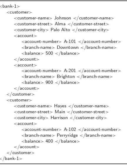
r Elements can be nested inside other elements, to any level of nesting.Table 52.5shows a
represen-tation of the bank information from Table 52.4, but withaccountelements nested withincustomer elements.
The nested representation permits representation of complex information within a single docu-ment. For instance, a purchase order element may have within it elements representing the supplier, customer, and each of the parts ordered. Each of these elements, in turn, may have subelements; for instance, a part element may have subelements for its part number, name, and price.
Although the nested representation makes it easier to represent some information, it can result in redundancy; for example, the nested representation of the bank database would store anaccount element redundantly (multiple times) if it is owned by multiple customers.
Nested representations are widely used inXMLdata interchange applications to avoid joins. For instance, a shipping application would store the full address of sender and receiver redundantly on a shipping document associated with each shipment, whereas a normalized representation may require a join of shipping records with acompany-addressrelation to get address information.
r Because theXMLformat is widely accepted, a wide variety of tools are available to assist in its
TABLE 52.5 NestedXMLRepresentation of Bank Information
<bank-1> <customer>
<customer-name>Johnson</customer-name> <customer-street>Alma</customer-street> <customer-city>Palo Alto</customer-city> <account>
<account-number>A-101</account-number> <branch-name>Downtown</branch-name> <balance>500</balance>
</account> <account>
<account-number>A-201</account-number> <branch-name>Brighton</branch-name> <balance>900</balance>
</account> </customer> <customer>
<customer-name>Hayes</customer-name> <customer-street>Main</customer-street> <customer-city>Harrison</customer-city> <account>
<account-number>A-102</account-number> <branch-name>Perryridge</branch-name> <balance>400</balance>
</account> </customer> </bank-1>
Just asSQLis the dominantlanguagefor querying relational data,XMLis becoming the dominantformat for data exchange.
In addition to elements,XMLspecifies the notion of anattribute. For example, the type of an account is represented below as an attribute namedacct-type.
. . .
<account acct-type= “checking”>
<account-number>A-102</account-number> <branch-name>Perryridge</branch-name> <balance>400</balance>
</account> . . .
The attributes of an element appear asname=valuepairs before the closing “>” of a tag. Attributes are strings and do not contain markup. Furthermore, an attribute name can appear only once in a given tag, unlike subelements, which may be repeated.
Note that in a document construction context, the distinction between subelement and attribute is important — an attribute is implicitly text that does not appear in the printed or displayed document. However, in database and data exchange applications ofXML, this distinction is less relevant, and the choice of representing data as an attribute or a subelement is often arbitrary.
For instance, theDTDfor theXMLdata inTable 52.5is shown below: <!DOCTYPE bank [
<!ELEMENT bank (customer*)>
<!ELEMENT customer ( customer-name customer-street customer-city account+)> <!ELEMENT customer-name( #PCDATA )>
<!ELEMENT customer-street( #PCDATA )> <!ELEMENT customer-city( #PCDATA )>
<!ELEMENT account ( account-number branch-name balance )> <!ELEMENT account-number ( #PCDATA )>
<!ELEMENT branch-name ( #PCDATA )> <!ELEMENT balance( #PCDATA )>
]>
The aboveDTDindicates that a bank may have zero or morecustomersubelements. Eachcustomerelement has a single occurrence of each of the subelementscustomer-name,customer-street, andcustomer-city, and one or more subelements of typeaccount. These subelementscustomer-name,customer-street, and
customer-cityare declared to be of type#PCDATA, indicating that they are character strings with no
further structure (PCDATAstands for “parsed character data”). Eachaccountelement, in turn, has a single occurrence of each of the subelementsaccount-number,branch-name, andbalance.
The followingDTDillustrates a case where the nesting can be arbitrarily deep; such a situation can arise with complex parts that subparts that themselves have complex subparts, and so on.
<!DOCTYPE parts [
<!ELEMENT part (name, subpartinfo*)> <!ELEMENT subpartinfo (part, quantity)> <!ELEMENT name ( #PCDATA )> <!ELEMENT quantity ( #PCDATA )>
]>
The aboveDTDspecifies that a part element may contain within it zero or more subpart elements, each of which in turn contains a part element.DTDs such as the above, where an element type is recursively contained within an element of the same type, are calledrecursive DTDs. TheXMLSchemalanguage plays the same role asDTDs, but is more powerful in terms of the types and constraints it can specify.
TheXPathandXQuerylanguages are used to queryXMLdata. The XQuery language can be thought of as an extension ofSQLto handle data with nested structure, although its syntax is different from that ofSQL.
Many database systems storeXMLdata by mapping them to relations. Unlike in the case ofE-Rdiagram to relation mappings, theXMLto relation mappings are more complex and done transparently. Users can write queries directly in terms of theXMLstructure, usingXMLquery languages.
In summary, theXMLlanguage provides a flexible and self-documenting mechanism for modeling data, supporting a variety of features such as nested structures and multivalued attributes, and allowing multiple types of data to be represented in a single document. Although the basicXMLmodel allows data to be arbitrarily structured, the schema of a document can be specified usingDTDs or the XMLSchema language. Both these mechanisms allow the schema to be flexibly and partially specified, unlike the rigid schema of relational data, thus supportingsemi-structured data.
52.5 Further Reading
r The Relational Model.The relational model was proposed by E.F. Codd of theIBMSan Jose
University of California at Berkeley (Stonebraker [Sto86b]), and Query-by-Example at theIBMT.J. Watson Research Center (Zloof [Zlo77]).
General discussion of the relational data model appears in most database texts, including Date [Dat00], Ullman [Ull88], Elmasri and Navathe [EN00], Ramakrishnan and Gehrke [RG02], and Silberschatz et al. [SKS02]. Textbook descriptions of theSQL-92language include Date and Darwen [DD97] and Melton and Simon [MS93].
Textbook descriptions of the network and hierarchical models, which predated the relational model, can be found on the Web sitehttp://www.db-book.com (this is the Web site of the text by Silberschatz et al. [SKS02])
r The Object-Based Models.
– The Entity-Relationship Model.The entity-relationship data model was introduced by Chen [Che76]. Basic textbook discussions are offered by Elmasri and Navathe [EN00], Ramakrish-nan and Gehrke [RG02], and Silberschatz et al. [SKS02]. Various data manipulation languages for theE-Rmodel have been proposed, although none is in widespread commercial use. The concepts of generalization, specialization, and aggregation were introduced by Smith and Smith [SS77].
– Object-Oriented Models. Numerous object-oriented database systems were implemented as either products or research prototypes. Some of the commercial products include ObjectStore, Ontos, Orion, and Versant. More information on these may be found in overviews of object-oriented database research, such as Kim and Lochovsky [KL89], Zdonik and Maier [ZM90], and Dogac et al. [DOBS94]. TheODMGstandard is described by Cattell [Cat00].
Descriptions ofUMLmay be found in Booch et al. [BJR98] and Fowler and Scott [FS99]. – Object-Relational Models. The nested relational model was introduced in [Mak77] and [JS82].
Design and normalization issues are discussed in [OY87, [RK87], and [MNE96].POSTGRES ([SR86] and [Sto86a]) was an early implementation of an object-relational system. Commercial databases such as IBM DB2, Informix, and Oracle support various object-relational features of SQL:1999. Refer to the user manuals of these systems for more details.
Melton et al. [MSG01] and Melton [Mel02] provide descriptions of SQL:1999; [Mel02] em-phasizes advanced features, such as the object-relational features, of SQL:1999. Date and Darwen [DD00] describes future directions for data models and database systems.
r XML. The XML Cover Pages site (www.oasis-open.org/cover/) contains a wealth of XML
infor-mation, including tutorial introductions toXML, standards, publications, and software. The World Wide Web Consortium (W3C) acts as the standards body for Web-related standards, including basicXMLand all theXML-related languages such asXPath,XSLT, andXQuery. A large number of technical reports defining theXMLrelated standards are available atwww.w3c.org.
A large number of books onXMLare available in the market. These include [CSK01], [CRZ03], and [W+00].
Defining Terms
Attribute: 1. A descriptive feature of an entity or relationship in the entity-relationship model. 2. The name of a column header in a table, or, in relational-model terminology, the name of a domain used to define a relation.
Class: A set of objects in the object-oriented model that contains the same types of values and the same methods; also, a type definition for objects.
Data model: A collection of conceptual tools for describing the real-world entities to be modeled in the database and the relationships among these entities.
Element: The contents between a start tag and its corresponding end tag in an XML document.
Entity: A distinguishable item in the real-world enterprise being modeled by a database schema.
Functional dependency: A rule stating that given values for some set of attributes, the value for some other set of attributes is uniquely determined. X functionally determines Y if whenever two tuples in a relation have the same value on X, they must also have the same value on Y.
Generalization: A superclass; an entity set that contains all the members of one or more specialized entity sets.
Instance variable: attribute values within objects.
Key: 1. A set of attributes in the entity relationship model that serves as a unique identifier for entities. Also known assuperkey. 2. A set of attributes in a relation schema that functionally determines the entire schema. 3.Candidate key: a minimal key. 4.Primary key: a candidate key chosen as the primary means of identifying/accessing an entity set, relationship set, or relation.
Message: The means by which an object invokes a method in another object.
Method: Procedures within an object that operate on the instance variables of the object and/or send messages to other objects.
Normal form: A set of desirable properties of a schema. Examples include the Boyce-Codd normal form and the third normal form.
Object: Data and behavior (methods) representing an entity.
Persistence: The ability of information to survive (persist) despite failures of all kinds, including crashes of programs, operating systems, networks, and hardware.
Relation: 1. A subset of a Cartesian product of domains. 2. Informally, a table.
Relation schema: A type definition for relations, consisting of attribute names and a specification of the corresponding domains.
Relational algebra: An algebra on relations; consists of a set of operations, each of which takes as input one or more relations and returns a relation, and a set of rules for combining operations to create expressions.
Relationship: An association among several entities.
Subclass: A class that lies below some other class (a superclass) in a class inheritance hierarchy; a class that contains a subset of the objects in a superclass.
Subtable: A table such that (a) its tuples are of a type that is a subtype of the type of tuples of another table (the supertable), and (b) each tuple in the subtable has a corresponding tuple in the supertable.
Specialization: A subclass; an entity set that contains a subset of entities of another entity set.
References
[BJR98] G. Booch, I. Jacobson, and J. Rumbaugh.The Unified Modeling Language User Guide. Addison-Wesley, 1998.
[CAB+81] D.D. Chamberlin, M.M. Astrahan, M.W. Blasgen, J.N. Gray, W.F. King, B.G. Lindsay, R.A. Lorie, J.W. Mehl, T.G. Price, P.G. Selinger, M. Schkolnick, D.R. Slutz, I.L. Traiger, B.W. Wade, and R.A. Yost. A history and evaluation of System R.Communications of the ACM, 24(10):632–646, October 1981.
[Cat00] R. Cattell, Editor.The Object Database Standard: ODMG 3.0. Morgan Kaufmann, 2000. [Che76] P.P. Chen. The Entity-Relationship model: toward a unified view of data.ACM Transactions on
Database Systems, 1(1):9–36, January 1976.
[Cod70] E.F. Codd. A relational model for large shared data banks.Communications of the ACM, 13(6): 377–387, June 1970.
[CRZ03] A.B. Chaudhri, A. Rashid, and R. Zicari.XML Data Management: Native XML and XML-Enabled Database Systems. Addison-Wesley, 2003.
[CSK01] B. Chang, M. Scardina, and S. Kiritzov.Oracle9i XML Handbook. McGraw-Hill, 2001. [Dat00] C.J. Date.An Introduction to Database Systems. Addison-Wesley, 7th edition, 2000. [DD97] C.J. Date and H. Darwen.A Guide to the SQL Standard. Addison-Wesley, 4th edition, 1997. [DD00] C.J. Date and H. Darwen.Foundation for Future Database Systems: The Third Manifesto. Addison
[DOBS94] A. Dogac, M.T. Ozsu, A. Biliris, and T. Selis.Advances in Object-Oriented Database Systems, volume 130. Springer Verlag, 1994. Computer and Systems Sciences, NATO ASI Series F.
[EN00] R. Elmasri and S.B. Navathe.Fundamentals of Database Systems. Benjamin Cummings, 3rd edition, 2000.
[FS99] M. Fowler and K. Scott.UML Distilled: A Brief Guide to the Standard Object Modeling Language. Addison-Wesley, 2nd edition, 1999.
[JS82] G. Jaeschke and H.J. Schek. Remarks on the algebra of non first normal form relations. InProc. of the ACM SIGMOD Conf. on Management of Data, pages 124–138, 1982.
[KL89] W. Kim and F. Lochovsky, Editors.Object-Oriented Concepts, Databases, and Applications. Addison-Wesley, 1989.
[Mak77] A. Makinouchi. A consideration of normal form on not-necessarily normalized relations in the relational data model. InProc. of the International Conf. on Very Large Databases, pages 447–453, 1977.
[Mel02] J. Melton.Advanced SQL: 1999 — Understanding Object-Relational and Other Advanced Features. Morgan Kaufmann, 2002.
[MNE96] W.Y. Mok, Y.-K. Ng, and D.W. Embley. A normal form for precisely characterizing redundancy in nested relations.ACM Transactions on Database Systems, 21(1):77–106, March 1996.
[MS93] J. Melton and A.R. Simon.Understanding the New SQL: A Complete Guide. Morgan Kaufmann, 1993.
[MSG01] J. Melton, A.R. Simon, and J. Gray.SQL: 1999 — Understanding Relational Language Components. Morgan Kaufmann, 2001.
[OY87] G. Ozsoyoglu and L. Yuan. Reduced MVDs and minimal covers.ACM Transactions on Database Systems, 12(3):377–394, September 1987.
[RG02] R. Ramakrishnan and J. Gehrke.Database Management Systems. McGraw-Hill, 3rd edition, 2002. [RK87] M.A. Roth and H.F. Korth. The design of¬1nf relational databases into nested normal form. In
Proc. of the ACM SIGMOD Conf. on Management of Data, pages 143–159, 1987.
[SKS02] A. Silberschatz, H.F. Korth, and S. Sudarshan.Database System Concepts. McGraw-Hill, 4th edition, 2002.
[SR86] M. Stonebraker and L. Rowe. The design of postgres. InProc. of the ACM SIGMOD Conf. on Management of Data, 1986.
[SS77] J.M. Smith and D.C.P. Smith. Database abstractions: aggregation and generalization.ACM Trans-actions on Database Systems, 2(2):105–133, March 1977.
[Sto86a] M. Stonebraker. Inclusion of new types in relational database systems. InProc. of the International Conf on Data Engineering, pages 262–269, 1986.
[Sto86b] M. Stonebraker, Editor.The Ingres Papers. Addison-Wesley, 1986.
[Ull88] J.D. Ullman.Principles of Database and Knowledge-base Systems, Volume 1. Computer Science Press, Rockville, MD, 1988.
[W+00] K. Williams (Editor) et al.Professional XML Databases. Wrox Press, 2000.
53
Tuning Database
Design for High
Performance
Dennis Shasha
Courant Institute New York University
Philippe Bonnet
University of Copenhagen
53.1 Introduction 53.2 Underlying Principles
What Databases Do • Performance Spoilers 53.3 Best Practices
Tuning Hardware • Tuning the Operating System •Tuning Concurrency Control •Indexes •Tuning Table Design 53.4 Tuning the Application Interface
Assemble Object Collections in Bulk • Cursors Cause Friction •The Art of Insertion
53.5 Monitoring Tools 53.6 Tuning Rules of Thumb 53.7 Summary and Research Results
53.1 Introduction
In fields ranging from arbitrage to tactical missile defense, speed of access to data can determine success or failure. Database tuning is the activity of making a database system run faster. Like optimization activities in other areas of computer science and engineering, database tuning must work within the constraints of its underlying technology. Just as compiler optimizers, for example, cannot directly change the underlying hardware, database tuners cannot change the underlying database management system.
The tuner can, however, modify the design of tables, select new indexes, rearrange transactions, tamper with the operating system, or buy hardware. The goals are to eliminate bottlenecks, decrease the number of accesses to disks, and guarantee response time, at least in a statistical sense.
Understanding how to do this well requires deep knowledge of the interaction among the different components of a database management system (Figure 53.1).
Application Programmer (e.g., business analyst, Data architect)
Sophisticated Application Programmer (e.g., SAP admin)
DBA, Tuner
Hardware [Processor(s), Disk(s), Memory]
Operating System
Concurrency Control Recovery
Storage Subsystem Indexes
Query Processor Application
FIGURE 53.1 Database system architecture. Database tuning requires deep knowledge of the interaction among the different components and levels of a database system.
53.2 Underlying Principles
To understand the principles of tuning, you must understand the two main kinds of database applications and what affects performance.
53.2.1 What Databases Do
At a high level of abstraction, databases are used for two purposes: online transaction processing and decision support.Online transaction processingtypically involves access to a small number of records, generally to modify them. A typical such transaction records a sale or updates a bank account. These transactions use indexes to access their few records without scanning through an entire table.E-commerce
applications share many of these characteristics, especially the need for speed — it seems that potential e-customers will abandon a site if they have to wait more than 7 seconds for a response.
Decision supportqueries, by contrast, read many records often from adata warehouse, compute an aggregate result, and sometimes apply that aggregate back to an individual level. Typical decision support queries are “find the total sales of widgets in the last quarter in the northeast” or “calculate the available inventory per unit item.” Sometimes, the results are actionable, as in “find frequent flyer passengers who have encountered substantial delays in their last few flights and send them free tickets and an apology.”
53.2.2 Performance Spoilers
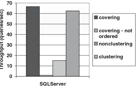
Having divided the database applications into two broad areas, we can now discuss what slows them down: 1. Imprecise data searches. These occur typically when a selection retrieves a small number of records from a large table, yet must search the entire table to find those data. Establishing an index may help in this case, although other actions, including reorganizing the table, may also have an effect (seeFigure 53.2).
0 0.2 0.4 0.6 0.8 1
SQLServer Oracle DB2
Throughput ratio
clustered nonclustered no index
FIGURE 53.2 Benefits of clustering index. In this graph, each query returns 100 records out of the 1,000,000 that the table contains. For such a query, a clustering index is twice as fast as a non-clustering index and orders of magnitude faster than a full table scan when no index is used; clustering and non-clustering indexes are defined below. These experiments were performed on DB2 UDB V7.1, Oracle8i, and SQL Server 7 on Windows 2000.
0 5 10 15 20 25
Query Selectivity
Throughput (queries/sec)
scan
non clustering
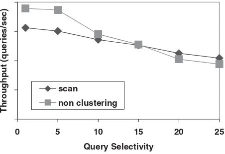
FIGURE 53.3 Index may hurt performances. We submit range queries selecting a variable portion of the underlying table and measure the performance using an index or a scan. We observe that the non-clustering index is better when the percentage of selected records is below a certain threshold. Above this threshold, a scan performs better because it is faster to sequentially access all records than to randomly access a relatively large portion of them (15% in this experiment). This experiment was performed using DB2 UDB V7.1 on Windows 2000.
bandwidth was about 20 Mb/sec while random bandwidth was about 200 KB/sec. (The variation depends on technology and on tunable parameters, such as the degree of prefetching and size of pages.) Non-clustered index accesses tend to be random, whereas scans are sequential. Thus, removing an index may sometimes improve performance, because either the index is never used for reading (and therefore constitutes only a burden for updates) or the index is used for reading and behaves poorly (see Figure 53.3).
0 100 200 300 400 500 600
loop no loop
throughput (records/sec)
FIGURE 53.4 Loop constructs. This graph compares two programs that obtain 2000 records from a large table (line item from TPC-H). Theloopprogram submits 200 queries to obtain this data, while theno loopprogram submits only one query and thus enjoys much better performance.
4. Delays due to lock conflicts. These occur either when update transactions execute too long or when several transactions want to access the same datum, but are delayed because of locks. A typical example might be a single variable that must be updated whenever a record is inserted. In the following example, theCOUNTERtable contains the next value which is used as a key when inserting values in theACCOUNTtable.
begin transaction
NextKey := select nextkey from COUNTER;
insert into ACCOUNT values (nextkey, 100, 200); update COUNTER set nextkey = NextKey + 1;
end transaction
When the number of such transactions issued concurrently increases,COUNTERbecomes a bot-tleneck because all transactions read and write the value ofnextkey.
As mentioned in the introduction, avoiding such performance problems requires changes at all levels of a database system. We will discuss tactics used at several of these levels and their interactions — hardware, concurrency control subsystem, indexes, and conceptual level. There are other levels, such as recovery and query rewriting, that we mostly defer to reference [4].
53.3 Best Practices
Understanding how to tune each level of a database system (seeFigure 53.1)requires understanding the factors leading to good performance at that level. Each of the following subsections discusses these factors before discussing tuning tactics.
53.3.1 Tuning Hardware
Each processing unit consists of one or more processors, one or more disks, and some memory. Assuming a 1-GIPS (billion instructions per second) processor, disks will be the bottleneck for online transaction processing applications until the processor is attached to around 10 disks (counting 500,000 instructions per random I/O issued by the database system and 200 random I/O per second). Each transaction spends far more time waiting for head movement on disk than in the processor.