METROLOGY OF IMAGE PROCESSING IN SPECTRAL REFLECTANCE
MEASUREMENT BY UAV
E. Honkavaara a, *, T. Hakala a, L. Markelin b, J. Peltoniemia, b
a
Finnish Geodetic Institute, Geodeetinrinne 2, 02430 Masala, Finland (Eija.Honkavaara, Teemu.Hakala, Lauri.Markelin, Jouni.Peltoniemi)@fgi.fi
b
University of Helsinki, PO Box 14, 00014, Finland (Jouni.Peltoniemi)@helsinki.fi
Commission I, WG I/4
KEY WORDS: Photogrammetry, Radiometry, Geometry, Reflectance, Metrology, Remotely Piloted Aircraft System, UAV
ABSTRACT:
Remote sensing based on unmanned airborne vehicles (UAVs) is rapidly developing field of technology. For many of potential UAV remote sensing applications, accurate reflectance measurements are required. Overall objective of our investigation is to develop a SI-traceable procedure for reflectance measurement using spectrometric image data collected by an UAV. In this article, our objective is to investigate the uncertainty propagation of image data post-processing. We will also present the first results of three traceable UAV remote sensing campaigns.
* Corresponding author.
1. INTRODUCTION
Remote sensing based on unmanned airborne vehicles (UAVs) is a rapidly developing field of technology. UAVs enable accurate, flexible and low cost measurements of 3D geometric, radiometric and temporal properties of land and vegetation by cameras and other instruments. With light weight systems, typical flying altitudes are 10 m – 150 m and the areal extent ranges typically from few m2 to few km2. UAVs can be used in various environmental remote sensing tasks, such as precision agriculture or water quality monitoring. They also offer an interesting alternative to produce reflectance reference measurements for satellite sensor and image calibration and validation (cal/val).
For many of potential applications of UAV imaging, accurate reflectance measurements are required. Overall objective of our investigation is to develop a SI-traceable procedure for reflectance data generation in local area applications using spectral image data collected by an UAV. SI-traceability is the core concept of metrology, which is the science of measurement, embracing both experimental and theoretical determinations at any level of uncertainty in any field of science and technology. According to the definitions by Bureau International des Poids (BIPM), metrological traceability is defined as "property of a measurement result whereby the result can be related to a reference through a documented unbroken chain of calibrations, each contributing to the measurement uncertainty”. The level of traceability establishes the level of comparability of the measurement: whether the result of a measurement can be compared to the previous one, a measurement result a year ago, or to the result of a measurement performed anywhere else in the world.
We have developed a traceable measurement chain for UAV remote sensing at the Finnish Geodetic Institute (FGI). The reflectance standard is obtained from the Metrology Research Institute of Aalto University, which is the Finnish National Standards Laboratory in optical quantities. The steps in the reflectance transfer are as follows: Availability of a SI-traceable reflectance standard in a national standards laboratory -> Traceable reflectance at the FGI laboratory -> Traceable reflectance in the measurement site -> Traceable reflectance in the UAV output data. The new procedure is based on measurement equipment existing at the FGI, and in this project our task has been to assess the uncertainties of different steps and the uncertainty propagation throughout the process.
In this article, our objective is to investigate the uncertainty of the last phase of the process, namely the image data post-processing, and to develop the uncertainty propagation for this process. Our objective for the output reflectance data accuracy is 1-2%. In the following, we will describe a method for error propagation in UAV remote sensing. We will also describe several traceable UAV remote sensing campaigns that were carried out in summer 2013.
2. PROCEDURE
2.1 Image data processing
We are using image data collected by a Fabry-Perot Interferometer-based spectrometric camera developed by the VTT Technology Research Center in Finland (Saari et al., 2011). This technology provides spectral data cubes with a rectangular image format, but each layer in the data cube has a slightly different position and orientation. Furthermore, the The International Archives of the Photogrammetry, Remote Sensing and Spatial Information Sciences, Volume XL-3/W1, 2014
technology allows stereoscopic and multiray views to objects Tens of observations from different directions are taken to each object point. Careful processing is required to obtain controlled and uniform reflectance output of this data.
The image processing chain includes image correction based on laboratory calibration, determination of orientations, DSM generation, atmospheric correction and reflectance data generation. The methods used in processing of the FPI spectral camera data are mostly generic methods for camera images;
2.2 Reflectance data generation using spectrometric UAV images
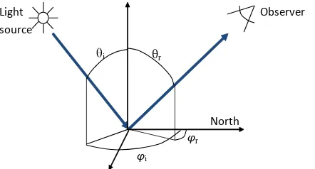
Our objective is to provide object bidirectional reflectance factors (BRF) using the UAV images.
In this investigation, we assume that the geometry of the measurement task is known so accurately that it does not cause any uncertainty to our process. This means that we have an accurate 3D model of the object surface and the orientations of the images. Furthermore, the time of imaging is known to provide the solar illumination geometry. Using this information, we can calculate all view/illumination-geometry related geometric quantities for the BRF extraction process with a are angles of incident and reflected light, respectively.
Our task is to process the image digital numbers (DNs) to BRFs
(R(θi,φi,θr,φr)). The process can be formulated as:
R(θi,φi,θr,φr) = f(DN) (1)
f(DN) is the function that carries out the reflectance transformation. We are using a block adjustment based approach for this process as described by Honkavaara et al., (2012, 2013). In this procedure, we use the image DNs as observations and determine the mathematical model for image
radiometry by minimizing the differences between the observed and modelled DN. This approach gives a possibility to determine rigorous models for image radiometry, including physical atmospheric model and accurate BRDF models for the objects.
With rectangular format images, the object is observed from different directions. Because of this, the images provide BRFs and the field of view (FOV) of the camera determines the range of observation anlges. For the FPI camera images, the observation angles are <±16° in the flight direction, <±27° in the cross-flight direction and <±31° the format corner.
We are using two measurement setups to provide object reflectance:
Vertical block is collected with camera optical axis pointing down. The FOV of the camera determines the view angles to the object; for the FPI camera the maximum observation angles are < 31°.
Another type of data collection is called oblique BRF block. In this case, the camera axis is tilted in the flight direction around the axis perpendicular to the flight direction; then the camera tilt and image FOV determine the BRF angles. The UAV is used to collect images around the object to provide wide range of observation angles. For example, with a camera axis tilted about 45° the observation angles are in the flight direction up to 60°.
2.3 Uncertainty propagation in reflectance calculation
Our central objective is to develop an uncertainty propagation method for reflectance calculation. When geometric aspects are solved, the major remaining uncertainty components in the BRF calculation include the noise of the CCD or CMOS image, σDN,
and the uncertainty of the reflectance transformation, σrefl_trans. This procedure assumes that the reflectance is derived from an individual image pixel value. If assuming that the individual uncertainty components are independent, the combined
uncertainty of the output reflectance σBRF is as follows:
2
The reflectance uncertainty estimation is implemented in the reflectance calculation process (Honkavaara et al., 2012; 2013) so that an uncertainty value is provided for each calculated reflectance value. When generating reflectance image mosaics, the uncertainty estimates can be stored as images covering the same spatial area as the image mosaic.
3. EMPIRICAL INVESTIGATION AND FIRST RESULTS
We performed three campaigns in different objects in order to investigate the new procedure. In the following, we describe the test setup of these campaigns and give the first results.
3.1 Equipment
We used an 8 rotor UAV, based on MikroKopter autopilot and Droidworx AD-8 extended frame (Figure 2). The central payload includes the FPI spectrometric camera and a high spatial resolution RGB camera for georeferencing purposes.
Figure 2. Top: MicroKopter UAV. Bottom: spectrometric FPI camera.
Our procedure is based on traceable reflectance panels that are distributed in the test areas (Figure 3):
Spectralon: a white Spectralon reference panel of size of 25 cm x 25 m, nominal reflectance 1.0
PTFE90: PTFE panel of size 1 m x 1 m, nominal reflectance 0.9
12 light grey pained panels, size 1 m x 1 m, nominal reflectance 0.50
2 dark grey panels made of grey carpet, size 1 m x 1 m, nominal reflectance 0.10
2 black panels made of black carpet, size 1 m x 1 m, nominal reflectance 0.05
Such a procedure was developed that the reference reflectance measurements of these reference targets are traceable to the national standards laboratory at Aalto University. BRFs of all the targets were measured at the FGI laboratory using the FIGIFIGO goniospectrometer (Suomalainen et al., 2009) and the new traceable procedure. In all the UAV campaigns, we carried out nadir reflectance factor measurements of the reference targets either using the ASD field spec pro FR spectrometer or Avantes hand held spectrometer, and normalized all the measurements to the traceable Spectralon panel. In some of the campaigns we carried out also BRF measurements by the FIGIFIGO.
Figure 3. Black, grey, light grey and white reflectance panels of size of 1 m x 1 m.
We used different methods to measure the illumination conditions and their changes during the UAV flights (Hakala et al., 2013) (Figure 4):
ASD Field Spec Pro FR spectrometer to measure incoming spectral irradiance,
Avantes hand held spectrometer to measure the reflected spectral solar radiance,
Microtops II sunphotometer to measure aerosol optical thickness at regular intervals.
An irradiance sensor belonging to the FPI camera system to measure wideband down welling irradiance in the wavelength range of 400-1000 nm
Figure 4. Measurement of illumination conditions using ASD spectrometer, Microtops sunphotometer and wideband irradiance sensor in the UAV.
3.2 Three validation campaigns
3.2.1 Sjökulla test site. The major test area was the Sjökulla remote sensing test field in Southern Finland (60.242064 N, 24.383585 E) (Honkavaara et al., 2008). The area is non-vegetated and covered with permanent, artificial reflectance and resolution targets made of gravel and it has also space for portable reflectance targets.
The measurement campaigns in Sjökulla took place in 26 June using the high spatial resolution and wide spectral bandwidth RGB camera to provide an accurate object surface model and in The International Archives of the Photogrammetry, Remote Sensing and Spatial Information Sciences, Volume XL-3/W1, 2014
6 August 2013 using the FPI spectrometric camera to provide object reflectance data. We collected the FPI images with nadir and oblique views. The oblique view angle in the oblique flight lines was about 30° providing the maximum observation angles of about 50°. The area of interest was of size of 100 m x 60 m. The flying height was 100 m and it provided a GSD of 10 cm for the FPI spectral camera images and a GSD of 2.7 cm for the RGB images at nadir. Figure 5 illustrates the setup of this campaign.
Figure 5. Traceable UAV campaign in Sjökulla remote sensing test field. From top: the image block with three vertical flight lines and two crossing oblique bi-directional flight lines; sample RGB image with ground control points; sample FPI image.
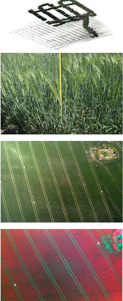
3.2.2 Vihti agricultural test area. Area 2 was the agricultural test field of the MTT Agrifood Research Finland, located in Vihti, Southern Finland (60.421691 N, 24.371706 E). The area was covered with barley of average height of 60 cm. Reference reflectance panels were distributed in the borders and centre area of the block. We collected vertical image blocks in 28 June 2013 using the FPI camera and RGB camera. The area of interest was about 250 m x 200 m. The flying height of 100 m provided a GSD of 10 cm for the FPI spectral camera images and a GSD of 2.7 cm for the RGB images. Figure 6 shows the setup of this campaign.
Fugure 6. Traceable UAV campaign in Vihti agricultural test field. From top: the image block with five vertical flight lines and two crossing flight lines; ground view; sample RGB image; sample FPI image.
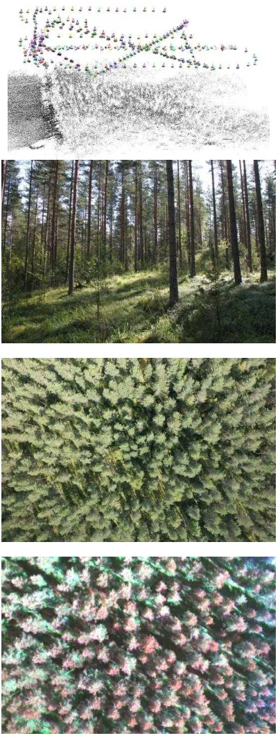
3.2.3 Evo forestry test area. Area 3 was a forest test site of the HAMK University of Applied Sciences, located in Evo, Hämeenlinna, Southern Finland (61.185687 N,25.118902 E). The target area was a homogenous Scots Pine forest; with an average tree height of 20 m. The reflectance reference panels were laid on the field north from the target forest area because it was not possible to distribute the targets uniformly around the object area inside the forest. The area covered with the flights was about 250 m x 300 m. Flying height was 100 m, providing a GSD of 10 cm for the FPI spectral camera images and a GSD of 2.7 cm for the RGB images. Figure 7 shows the setup of this campaign.
Figure 6. Traceable UAV campaign in Evo forestry test field. From top: the image block with four vertical flight lines and two
crossing oblique bi-directional flight lines; ground view; sample RGB image; sample FPI image.
4. CONCLUSIONS
We are developing traceable image processing methods for UAV remote sensing. Our first processing chain for reflectance data generation is based on traceable reflectance panels of size of 1 m x 1 m and on traceable Spectralon. The traceable reflectance is transferred to the FGI from the Metrology Research Institute of Aalto University. The uncertainties of observations are propagated through the image processing to provide estimates of the uncertainty of reflectance measurements. We carried out three traceable validation campaigns: one in flat non-vegetated area, one in agricultural fields and one in forest.
Consideration of traceability is a new approach in UAV data processing. We think that developing methods to provide reflectance data using UAV imagery and the rigorous assessment of the measurement uncertainty will be of great importance for many future applications of the UAV imagery.
5. REFERENCES
Web-pages of the MetEOC – European Metrology for Earth Observation and Climate http://www.emceoc.org/
Hakala, T.; Honkavaara, E.; Saari, H.; Mäkynen, J.; Kaivosoja, J.; Pesonen, L.; Pölönen, I. Spectral imaging from UAVs under varying illumination conditions. In International Archives of the Photogrammetry, Remote Sensing and Spatial Information Sciences, Volume XL-1/W2, 2013, Proceedings of UAV-g2013, Rostock, Germany, 4 – 6 September 2013.
Honkavaara, E.; J. Peltoniemi, E. Ahokas, R. Kuittinen, J. Hyyppä, J. Jaakkola, H. Kaartinen, L. Markelin, K. Nurminen, J. Suomalainen, 2008. A permanent test field for digital photogrammetric systems. Photogrammetric Engineering &
Remote Sensing, 74(1), pp. 95-106.
Honkavara, E., Hakala, T., Saari, H., Markelin, L., Mäkynen, J., Rosnell, T., 2012. A process for radiometric correction of UAV image blocks. Photogrammetrie, Fernerkundung,
Geoinformation (PFG), 2/2012.
Honkavaara, E.; Saari, H.; Kaivosoja, J.; Pölönen, I.; Hakala, T.; Litkey, P.; Mäkynen, J.; Pesonen, L, 2013. Processing and Assessment of Spectrometric, Stereoscopic Imagery Collected Using a Lightweight UAV Spectral Camera for Precision Agriculture. Remote Sens. 2013, 5, pp. 5006-5039.
Saari, H. ; Pölönen, I.; Salo, H. ; Honkavaara, E. ; Hakala, T., et al. Miniaturized hyperspectral imager calibration and UAV flight campaigns , Proc. SPIE 8889, Sensors, Systems, and Next-Generation Satellites XVII, 88891O (October 24, 2013); doi:10.1117/12.2028972; http://dx.doi.org/10.1117/12.2028972
Suomalainen, J.; Hakala, T.; Peltoniemi, J.; Puttonen, E. Polarised Multiangular Reflectance Measurements Using the Finnish Geodetic Institute Field Goniospectrometer. Sensors. 2009; 9(5):3891-3907. http://www.mdpi.com/1424-8220/9/5/3891
Wu, C. 2013. Towards Linear-time Incremental Structure From Motion, 3DV 2013.
Wu, C., Agarwal, S., Curless, B., Seitz, S.M. 2011. Multicore Bundle Adjustment, CVPR 2011.
6. ACKNOWLEDGEMENTS
We are grateful for European Metrology Research Program (EMRP) for funding of the project. The EMRP is jointly funded by the EMRP participating countries within the European Association of National Metrology Institutes (EURAMET) and the European Union.