HIGH AND LOW RESOLUTION TEXTURED MODELS OF COMPLEX
ARCHITECTURAL SURFACES
E. K. Stathopouloua, A. Valanisa, J. L. Lermab, A. Georgopoulosa
a
Laboratory of Photogrammetry, National Technical University of Athens – drag@central.ntua.gr b
Department of Cartographic Engineering, Geodesy and Photogrammetry, Universidad Politécnica de Valencia - jllerma@cgf.upv.es
KEY WORDS: 3D model, visualization, texture, UV mapping, constrained mesh, rendering
ABSTRACT:
During the recent years it has become obvious that 3D technology, applied mainly with the use of terrestrial laser scanners (TLS) is the most suitable technique for the complete geometric documentation of complex objects, whether they are monuments or architectural constructions in general. However, it is rather a challenging task to convert an acquired point cloud into a realistic 3D polygonal model that can simultaneously satisfy high resolution modeling and visualization demands. The aim of the visualization of a simple or complex object is to create a 3D model that best describes the reality within the computer environment. This paper is dedicated especially in the visualization of a complex object’s 3D model, through high, as well as low resolution textured models. The object of interest for this study was the Almoina (Romanesque) Door of the Cathedral of Valencia in Spain.
1. INTRODUCTION
While the generation of digital surface models has a long tradition and has evoked efficient solutions, the correct modeling of closed surfaces or free-form objects is of recent nature, a not completely solved problem and still an important issue investigated in many research activities (Remondino, 2003). The whole processing, from acquiring the data to visualizing the final 3D model of the object, is one of the most active research areas in the fields of optics, photogrammetry, computer vision, and computer graphics. Currently, the number of applications that include 3D models is unlimited in fields such as architecture, documentation of monuments, constructions, reverse engineering, field survey, industry, quality control, etc. A great deal of scientific articles has been published in order to propose various advancements in the processing workflow.
One major and partly unsolved problem is probably the visualization of a model, and in particular, the application of texture on it, especially for complex objects. The main focus of this paper is the creation
of high resolution textured models using
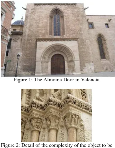
commercial software, employing different and combined workflows to create low resolution textured models that are both easy to handle and are appropriate for dissemination. The proposed workflow was originally developed and introduced by Valanis et al. (2010). In this paper, the workflow is implemented for a big, highly detailed and complex object, the Almoina (Romanesque) Door, one of the three main entrances in the Cathedral of Valencia (Fig. 1 & 2).
Figure 1: The Almoina Door in Valencia
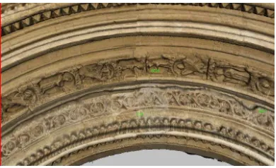
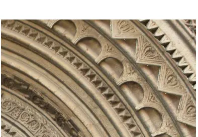
Figure 2: Detail of the complexity of the object to be described by a mesh
In order to fully document an object, contemporary photogrammetric tools combining terrestrial laser scanning data and digital photogrammetry can be used to yield detailed photorealistic models. All the required data can be acquired with the use of:
• a terrestrial laser scanner
• a total station
• a camera
and two cameras: one DSLR high resolution and one simple, compact camera. Although this type of terrestrial laser scanners is not the most appropriate for these cases of highly detailed objects, the results of the final models are considered satisfactory (Stathopoulou et al. 2010).
2. MOTIVATION
Traditionally, photogrammetry has been the most appropriate tool for the documentation of a variety of complex objects, whether they are architectural constructions, sculptures or monuments in general. Usually, the products of such processes are rectified images or orthophotos, orthophotomosaics and developments. During the recent years, due to the spectacular technological advances and the use of
terrestrial laser scanners and digital
photogrammetry, the workflow for the creation of these products is continuously being revisited and updated. Moreover, the combined utilization of computer graphics methods and algorithms in documentation applications has led to the addition of several new but non-metric products such as orthographic-view renderings, multi-image-based renderings and texture maps. In this respect, the combination of 3D acquisition systems with photogrammetric processes still remains a very challenging task which includes some unsolved problems.
It is desired that the 3D model should not only be detailed, but also suitable and easy to handle. For that purpose, a combination of classical surveying methods, laser scanning, photogrammetric and computer graphics processes should be used. Through such a workflow satisfactory accuracies may be achieved, but also the display of the offered by commercial software, a rather automated “black box” method, which uses the 3D model in a TIN, DXF, or OBJ format and high resolution images. With careful work and significant user
input, the results could be impressive.
Unfortunately, the results of these procedures are not suitable for dissemination purposes, because of the large-volume files that are created and the various proprietary formats. In order to solve this problem, the end results often need to be displayed into separate pieces that may belong to different layers or even archives.
Alternatively, the workflow would commence with the application of surface data decimation, taking care so that irreplaceable information displayed on the object does not get smoothed out. From that low resolution mesh, a flat texture map may be created. The photogrammetric processing of some images is also obligatory; in order to project them onto the maps of 4096 by 4096 pixels and thus get really rich texture for heavily reduced geometric models.
By the use of these special computer graphics procedures, it is possible to make an important update of the currently applied workflows and revisit the way that the results of close range applications are visualized. By employing the proposed workflow, multipurpose virtual objects and even environments that carry highly detailed textures can be created. Arguing the importance of
the proposed methods and highlight the
improvement that could be brought into related applications, a few well known problems, caused by existing solutions, are listed below:
• High resolution textured point clouds that are still difficult to be provided over the internet, cannot be imported into most animation software or game engines. Also, when using textured point clouds it is difficult to deal with colour differences that are due to variant illumination conditions during texture data acquisition whether acquiring the texture by a scanner or by a camera.
• Virtual CAD models often fail in comparison to the actual surface models regarding geometric detail.
• Detailed surface models with a colour value provided on each mesh node usually appear fuzzy and a great deal of detail is lost.
• Finally, 3D models of full geometric detail and high texture resolution such as those created by Callieri et al. (2008) are often difficult to display, handle and even load for most applications.
3. HIGH RESOLUTION TEXTURED MODELS
As mentioned above, commercial software provides the user the opportunity to employ texture on high resolution models. Although the results are a function of the complexity and the size of the object, it could give satisfactory results in cases of small or simpler objects. This software gives the option to project and drape the texture information onto the surface, usually using orthographic projections, which simplifies the texturing process (Lerma et al., 2008). For this specific study (Fig. 3), two commercial software packages were used: Topcon Image Master® and Technodigit 3DReshaper®.
3.1 Topcon Image Master
careful choosing the viewing angle of the object, because this affects the way the pixels are being projected onto the surface.
Figure 3: High resolution 3D model after the processing
If more than one image is required to texture a model, the results are not satisfactory enough. Especially for objects with comprehensive detail, such as the Almoina Door. Processing is rather tedious, because many trials have to be done until the best combination of images is found. It has to be mentioned that this software is photogrammetric and allows the user to do all the conventional photogrammetric procedures (orientations, etc.), then insert a 3D model and apply on it the texture coming from the oriented images. Image Master is one of the few photogrammetric programs that allow the user to import a 3D mesh in the form of a DXF or a TIN file and apply textures on the surface based on images that are photogrammetrically oriented. Unfortunately, due to the size of the files, it was impossible to create a texture map for the entire surface (around 8.000.000 triangles). For that reason, the surface was cut into different smaller pieces (that consist of less than 800.000 triangles), without overlap, so they could be handled easier. Some examples of the results are displayed in Fig. 4 and Fig. 5.
Figure 4: Textured sub-mesh of the arches
Figure 5: Textured sub-mesh of the columns
The final models were exported in VRML format and the texture images were associated with the respective 3D mesh pieces.
3.2 3DReshaper
The 3DReshaper software is originally designed for handling 3D content. It ranges from registering the point clouds to texturing the mesh. It is much simpler to employ in these cases, because it projects the image on the model after estimating a perspective transformation between the model and the image (Fig. 6).
Figure 6: The projection of the image on part of the surface
The advantage of handling the data in this way is that the images do not have to be oriented, and that with only 3 conjugate points the transformation can be estimated. Obviously, better control can be achieved by adding more points. Moreover, the combination of two images for the texture of the same surface delivered quite satisfactory products in this case. The disadvantages are, alike in most software, that the surface should be cut into pieces (smaller sub-meshes in different layers or even files) and also that the images should be of low-resolution, i.e. under 10 MB. This is necessary because it is quite impossible to handle very large files with a normal processor.
uniform resolution and radiometry. The results can be characterized as satisfactory, although there were some gaps displayed in white colour due to lack of information (Fig. 7, 8). Also, in some cases, entire regions were attributed wrong color, profoundly due to bad projection of the pixels.
Figure 7: High resolution textured model with some white regions
Figure 8: Result after texturing of a complex part of the object
The incompatibility of the exported files is also a problem, because most of the commercial software is not able to load the texture, especially in certain file formats.
Finally, the textured meshes were exported in OBJ format and each mesh was attached with the respective image or images.
4. LOW RESOLUTION TEXTURED MODELS
For optimizing the results, the methods described above needed to be revised. The alternative method includes a UV mapping process. UV mapping transforms the 3D object/mesh onto a flat image which can then be used to attach textural information. When a model is created as a polygon mesh using a 3D modeler, UV coordinates can be generated for each vertex in the mesh. Once the UV map is created, the user can paint/colour this UV map and then project it back to the 3D model, making it easier to correctly colour a 3D model (Lerma et al., 2008). In order to apply a UV mapping the created surface has to be simplified. The mesh volume should be reduced but without losing irreplaceable information. 3D processing software provide a variety of decimation algorithms, but in this way the user is not able to control most of the parameters of the process. Therefore, in this case, it was preferred to reduce the data by manually constructing a constrained mesh and not to employ
an automatic process provided by some commercial software. In this way the user is able to choose which information is irreplaceable and which not. A constrained mesh is a collection of quads that is usually manually designed onto a 3D mesh. This mesh is composed of mostly well shaped, nearly regular tetrahedra. The quality of this mesh and the shape of the tetrahedra depend on the curvature and the complexity of the original mesh. In some regions, however, it may be necessary to form triangles as well.
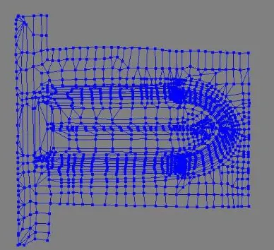
In this case, due to the complexity of the surface, care was taken so that all of the contours and edges that define the shape of the object are followed as closely as possible (Fig. 9). This procedure was done manually. Despite the fact that it is time consuming, the polygons created were much easier to handle than the triangles. The constrained mesh was designed in GSI Studio (Geometric Systems Inc.). The final mesh was formed by around 50.000 triangles.
(a)
(b)
Figure 9: Constrained mesh: (a) General view; (b) Close-up view
To create a flat texture map that is linked to the 3D constrained mesh, this constrained mesh was later imported in a UV mapping software, Deep UV
(Right Hemisphere) (Fig. 10).
Figure 10: The development of part of the mesh
This is achieved using a Matlab script that was developed at the Laboratory of Photogrammetry. The algorithm employed actually utilizes the orientation parameters of a given image and the collinearity equation in order to isolate the area of the object that is visible in an image, taking also into consideration the surface orientation in order to exclude backfacing and poorly imaged triangles, and link each of the visible TIN vertices onto that original image by means of an OBJ file. In this way, for each one of the oriented images a file containing the visible model area is created and the respective image is linked to it as its texture map.
Figure 11: Projection of one image onto the constrained mesh
After all individual images have been processed; the partial models created are imported into 3DStudio Max. In this software, via a texture rendering process, which is based on a projection that is defined between the partial models and the constrained mesh, the texture of the original images is transferred to the texture map of the constrained mesh. In this respect a number of partial texture maps are created and all are later combined and blended into Adobe Photoshop manually.
The above described workflow is summarized in the following table:
PROCESS SOFTWARE USED
Creation of the constrained mesh
GSI Studio
Photogrammetric processing of images
Image Master
Projection of the images onto the constrained
mesh
Matlab
Texture Map Creation Deep UV
Rendering 3DStudio Max
Texture Maps Combination
Adobe Photoshop
5. CONCLUSIONS
By employing the proposed workflow there is great potential in producing high resolution textures for large architectural objects or vast archaeological sites. The results can be easily delivered in different kinds of highly portable formats such as OBJ, VRML, 3DS etc. and thus there is a significant increase in the range of applications and software that can accept the final 3D textured models as input. Moreover, the authors are experimenting with different kinds of maps and their combinations namely for true complex objects. The purpose is to explore the quality of the outcome and to find ways to produce realistic representations, avoiding large amount of data and detailed surface models, easy to view in a simple web viewer. In this case study, the file sizes were considerably decreased up to 200 times.
Despite the whole processing is very time consuming and requires automation, it is shown that a light-weight 3D model can be eventually created and integrated into any animation software, game engine, virtual environment, web mapping service, stereoscopic rendering software, etc. All aspects of the production workflow are presented and discussed.
REFERENCES
M. Callieri, P. Cignoni, M. Corsini, R. Scopigno,
2008. Masked photo blending: Mapping dense
photographic data set on high-resolution sampled 3D models. Computer & Graphics, Volume 32, Issue 4, August 2008, Pages 4
Remondino, F., 2003 From Point Cloud to Surface,
the modeling and visualization problem,
International Archives of the Photogrammetry, Remote Sensing and Spatial Information Sciences, Vol. XXXIV-5/W10.
E.K. Stathopoulou, J.L. Lerma, A. Georgopoulos,
Geometric Documentation of the Almoina Door of the Cathedral of Valencia, 2010, Euromed Conference 2010, Limassol, Cyprus
A. Valanis, S. Fournaros, A. Georgopoulos,
Photogrammetric texture mapping of complex objects, 2010, Euromed Conference, Limassol, Cyprus
Lerma Garcia, J.L, Van Genechten, B., Heine, E., Santana Quintero, M. (eds), 2008: Theory and practice on Terrestrial Laser Scanning. Training
material based on practical applications.