Journal of Physics: Conference Series
PAPER • OPEN ACCESS
Development of digital viscometer based on
sensor technology and microcontroller
To cite this article: Yulkifli et al 2018 J. Phys.: Conf. Ser. 1040 012047
View the article online for updates and enhancements.
Related content
Two Different Multisensors Fabricated by Various Manufacturing Methods Duk-Soo Eun, Jang-Kyoo Shin and Jong-Hyun Lee
-Sensors: Danes sense new demand Micihael de Lame
-Design of embedded system to determine liquid refractive index based on ultrasonic sensor using an ATMega328
Y Radiyonoa, S Surantoro, P Pujayanto et al.
1234567890 ‘’“”
International Conference on Mathematics and Natural Sciences (IConMNS 2017) IOP Publishing IOP Conf. Series: Journal of Physics: Conf. Series 1040 (2018) 012047 doi :10.1088/1742-6596/1040/1/012047
Development of digital viscometer based on sensor technology
and microcontroller
Yulkifli, Yohandri and R Kurniati
Physics Department, Faculty of Mathematics and Natural Science, Universitas Negeri Padang, Jl. Prof. Hamka, Padang, Sumatera Barat, Indonesia 25131
E-mail: [email protected]
Abstract. The development of a digital Viscometer of fluid using photodiode and ultrasonic
sensor has been done. The time taken of the ball to pass a distance in the fluid is controlled using two photodiode sensors. On the other hand, the ultrasonic sensor is used to measure the distance between the photodiode sensors. An Arduino microcontroller is used as data processing and interfacing with digital displays (LCD). The Viscometer system is validated by an expert and a valid criterion is obtained of 91.67%. Empirically, the measurement error of the system is obtained of 0.5%. Viscosity measurement is carried out on three types of fluid which are glycerine, oil and cooking oil. Based on the measured data, the viscosity of the glycerine, oil and cooking oil are 1.12 Pa s, 0.78 Pa s and 0.39 Pa s, respectively. The satisfy result show the digital Viscometer is promising to be used in industry and schools as a tool to improve the understanding of the viscosity concept of the student.
1. Introduction
Physics has provided a strong foundation of technological evolution. Advances in the physical sciences such as sensor systems, components, electronic circuits, and materials provide a considerable impact on the development of technology. Therefore, understanding the concepts of physics in teaching is very important. An experiment is an important instrument for understanding the concepts of physics. In general, some experimental instrument in laboratory is working manually, where less effective and efficient. Manual instrument is produced lack of proper data due to some mistakes made in the experiment, such as general and systematic error. In systematic error, the calibration and parallax error greatly affect to the quality of the measured data. Viscometer is one the experiment system that requires a accuracy and precision system
2
1234567890 ‘’“”
International Conference on Mathematics and Natural Sciences (IConMNS 2017) IOP Publishing IOP Conf. Series: Journal of Physics: Conf. Series 1040 (2018) 012047 doi :10.1088/1742-6596/1040/1/012047
The digital viscometer is composed of a pair of photodiode sensors and ultrasonic sensors. Photodiode sensor is a semiconductor device with a p-n junction that designed to operate in reverse bias as a light detection [5]. This photodiode is operated as timer controller, where the ball passes the first sensor the timer is started and when the second sensor the timer is stopped. A pair of these sensors can be shifted upwards or downwards in order to vary the distance of the ball fall in the liquid. Ultrasonic sensors (Figure 1a) is a sensor works by emitting ultrasonic wave and receive a reflection of waves that can be used to interpret the distance of an object [6].
Arduino microcontroller (Figure 1b) is an electronic component that can be programmed and execute the program. Microcontroller equipped with supporting peripherals to as a complete computer on a chip level. A simple microcontroller is an IC that comprises RAM, ROM, parallel I/O, counter, and a clock circuit [7]. A microcontroller is a microprocessor system in which there already exists CPU, Read Only Memory (ROM), Random Access Memory (RAM), Input-Output, timers, interrupts, clocks, and internal equipment others already interconnected and well organized in a single chip that is ready to be used [8]. Arduino is a microcontroller board that has been integrated with a microcontroller ATmega328. Arduino data will be displayed in a Liquid Crystal Display (LCD) module. LCD is a flat-panel display or other electronically modulated optical device that uses the light-modulating properties of liquid crystals.
(a) (b)
Figure 1. Part of the system, (a) ultrasonic sensor and (b) Arduino
2. Experimental
The digital viscosmeter built by several circuits and electronic components. Ranging from the power supply, Arduino, photodiode and ultrasonic sensor as well as LCD displays this experiment, three kinds of liquid is used as a sample and the sensor distance will be varied. The diagram block of digital viscometer is shown in Figure 2.
Figure 2. Block diagram of the digital Viscometer
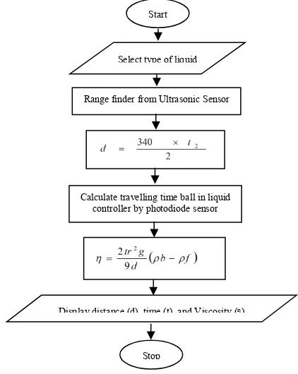
In this design, Arduino acts as a timer which is controlled by a pair of photodiode sensor. On the other hand, Arduino also serves to receive data from the ultrasonic sensors to determine the distance between two sensors. The schematic of the program inside the Arduino is presented in flow chart as shown in Figure 3.
Power Supply
Arduino Ultrasonic
Sensor Sensor 1
Sensor 2
1234567890 ‘’“”
International Conference on Mathematics and Natural Sciences (IConMNS 2017) IOP Publishing IOP Conf. Series: Journal of Physics: Conf. Series 1040 (2018) 012047 doi :10.1088/1742-6596/1040/1/012047
Figure 3. Flowchart of the software of the system
The accuracy of the system is determined based on measured results and know a coefficient of viscosity of the fluid. Each of the liquid samples are measured and compared with its standard coefficient of viscosity. Meanwhile, the determination of the precession of the system performed by take measurements repeated ten times for each sample fluid. Determine the average value, standard deviation, absolute error and relative error and report the results of measurements [9].
3. Results and Discussion
3.1. Results
3.1.1. Specification of the System
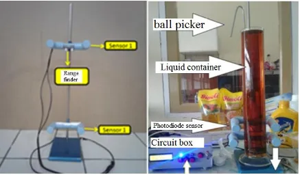
In general, the digital viscometer consists of sensor system, liquid container, and electronic system. Figure 4 are photographs of the sensor system and liquid containers. The sensor system is composed of a pair of photodiode for timer controller and ultrasonic sensors for a rangefinder. In addition, the glass tube is used as a container of fluid to be measured. Tubes with a height of 43 cm and a diameter of 8 cm, equipped with a hook ball. The circuit system installed in electronic case, which consists of an LCD display, push-button, power supply, Arduino, reset button, power on/off, sensor and AC ports. On the Arduino, 2, 3, 4, 5, 6, 7 port is used for the LCD display. Ports A0, A1, A2, and A3 are used for fluid and a reset button. Port 8.9 to sensor distance and port 5 Volt and the ground is used simultaneously as a voltage photodiode (Figure 5a). Box consists of two parts, front and rear. The front and back of the box can be seen in Figure 5b and 5c. The front part is where the LCD display, reset button, the on / off switch and three buttons for liquid selection. The rear consists of the AC port, fuse, and sensor ports. The port sensor has three pins including a proximity sensor pin, pin the start and stop of the sensor photodiode.
Start
Select type of liquid
Range finder from Ultrasonic Sensor
Calculate travelling time ball in liquid controller by photodiode sensor
Display distance (d), time (t), and Viscosity (ᶯ)
4
1234567890 ‘’“”
International Conference on Mathematics and Natural Sciences (IConMNS 2017) IOP Publishing IOP Conf. Series: Journal of Physics: Conf. Series 1040 (2018) 012047 doi :10.1088/1742-6596/1040/1/012047
Figure 4. Photograph of the sensor system and liquid container
Figure 5. Electronic system, a) electronic circuit, b) front and rear panel, and c) LCD display
3.1.2. Specification of the Design
1234567890 ‘’“”
International Conference on Mathematics and Natural Sciences (IConMNS 2017) IOP Publishing IOP Conf. Series: Journal of Physics: Conf. Series 1040 (2018) 012047 doi :10.1088/1742-6596/1040/1/012047
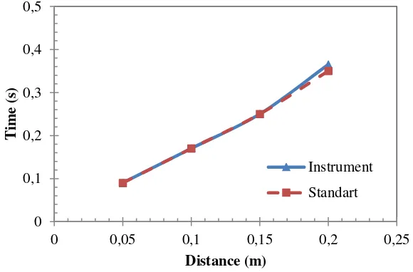
Figure 6. The relationship between the distance and the time for oil liquid
Figure 7. The relationship between the distance and the time for cooking oil liquid
0 0,2 0,4 0,6 0,8
0 0,05 0,1 0,15 0,2 0,25
Ti
m
e (
s)
Distance (m)
Instrument
Standart
0 0,1 0,2 0,3 0,4 0,5
0 0,05 0,1 0,15 0,2 0,25
Ti
m
e (
s)
Distance (m)
Instrument
6
1234567890 ‘’“”
International Conference on Mathematics and Natural Sciences (IConMNS 2017) IOP Publishing IOP Conf. Series: Journal of Physics: Conf. Series 1040 (2018) 012047 doi :10.1088/1742-6596/1040/1/012047
Figure 8. The relationship between the distance and the time for glycerine liquid
In Figure 6, comparison of measured and theoretical viscosity of the oil is presented. The measured data are approaching the theoretical value. The experiment proves that the value of the viscosity of 0.785 Pa s with accuracy percentage of 98%. In Figure7, the viscosity of cooking oil was 0.395 Pa s. As can be seen on the graph, the blue line is always close to the red line. So we can say with a theoretical approach viscosity measurement accuracy percentage of 98%. The glycerine has an average viscosity 1.112 Pa s and the percentage of accuracy of 99%. The relationship between the distance and the time for both measured and theoretical can be seen in Figure 8.
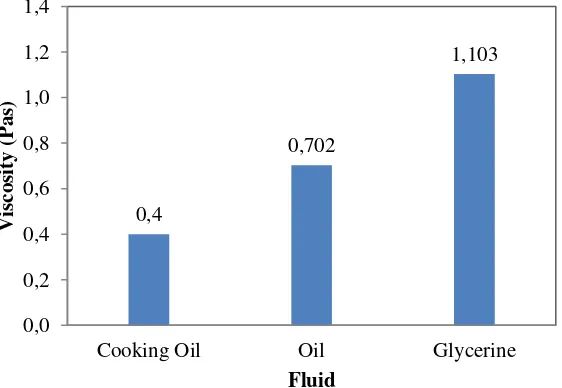
Different fluid types have different viscosity. Figure 9 shows the difference in viscosity fluid used in the experiment. The third type of fluid has a different coefficient value. Based on measured data, the viscosity coefficient of the oil, cooking oil and glycerine are 0.785 Pa s, 0.395 Pa s and 1.112 Pa s, respectively.
Figure 9. Comparison the viscosity coefficient of the liquids
1234567890 ‘’“”
International Conference on Mathematics and Natural Sciences (IConMNS 2017) IOP Publishing IOP Conf. Series: Journal of Physics: Conf. Series 1040 (2018) 012047 doi :10.1088/1742-6596/1040/1/012047
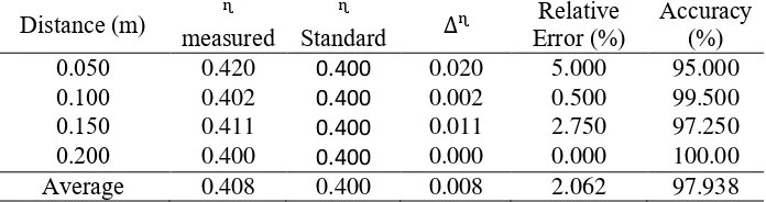
The accuracy of the system is obtained based on the repeated measurement. In this experiment, the ten repeated measurements are performed. The accuracy is calculated based on the average value, standard deviation, and error percentage. The repeated measured data for accuracy calculation are listed in Table 1, Table 2 and Table 3. Based on the data in tables, the accuracy of the system of glycerine, oil and cooking oil are 99.085%, 98.101% and 97.938%, respectively. Measurement error derived from the digital viscometer is smaller than an instrument that has been developed previously [9].
Table 1. The measurement accuracy of viscosity coefficient for the glycerine
Distance (m) ᶯ
Table 2. The measurement accuracy of viscosity coefficient for the oil
Distance (m) ᶯ
Table 3. The measurement accuracy of viscosity coefficient for the cooking oil
Distance (m) ᶯ
8
1234567890 ‘’“”
International Conference on Mathematics and Natural Sciences (IConMNS 2017) IOP Publishing IOP Conf. Series: Journal of Physics: Conf. Series 1040 (2018) 012047 doi :10.1088/1742-6596/1040/1/012047
4. Conclusion
The development of digital viscometer based on sensor technology and microcontroller has been presented. The digital viscometer is built consist of viscosity tube, photodiode and ultrasonic sensor, electronic circuit and instrument case. An electronic circuit is composed using Arduino kit, power supply circuit and LCD module. A pair of photodiode sensor acted as starter and stopper of the timer. In addition, the ultrasonic sensor is performed as a rangefinder between two photodiode sensors. The performance of the system in term of accuracy and practicality are satisfied for implementing in a physics experiment at school or laboratory. Based on the accuracy, precision and measured results, viscosity measurements can be performed more accurately and precisely.
Acknowledgment
The authors would like to thank Directorate General of Higher Education (DIKTI), Ministry of Research, Technology and Higher Education, Indonesia, for the Research Grant (Hibah TIM Pascasarjana 2017), No. 446/UN35.2/PG/2017.
References
[1] Sears Z 1954 University Physics Mechanics, Heat, and Sound (USA: Addison-Wesley Publishing Company)
[2] Setiadi 2012 Pengukuran Viskositas Bola Jatuh Fluida Dengan Mikrokontroler Atmega 8535. (Jawa Tengah: Universitas Kristen Satya Wacana)
[3] Yulkifli and Yohandri 2016 Pengembangan Teknologi Sensor Menjadi Alat-Alat Praktikum Fisika Dalam Mendukung Implementasi Kurikulum 2013 Prosiding Semirata 22-23 Mei 2016 Palembang ISBN 978-60271798-1-3
[4] Ihsan N, Yulkifli and Yohandri 2017 Development of speed measurement system for Pencak Silat kick based on sensor technology IOP Conference Series: Materials Science and Engineering,
180 (1) 012171.
[5] Pandiangan J 2007 Perancangan Dan Penggunaan Photodiode Sebagai Sensor Penghindar Dinding Pada Robot Forklift (Medan: USU)
[6] Yulkifli 2011 Jurnal Otomasi, Kontrol & Instrumentasi3 (3) 1-10.
[7] Yohandri 2013 Mikrokontroler dan Antar Muka (Padang: Universitas Negeri Padang)
[8] Heri S et al. 2013 Perancangan Sistem Telemetri Wireless Untuk Mengukur Suhu dan Kelembaban Berbasis Arduino Uno R3 Atmega328P dan XBEE PRO (Riau: Universitas Maritim Ali Haji)