Pro Windows Embedded
Compact 7
Producing Device Drivers
■ ■ ■
Pro Windows Embedded Compact 7
Copyright © 2011 by Abraham Kcholi
All rights reserved. No part of this work may be reproduced or transmitted in any form or by any means, electronic or mechanical, including photocopying, recording, or by any information storage or retrieval system, without the prior written permission of the copyright owner and the publisher.
ISBN-13 (pbk): 978-1-4302-4179-9 ISBN-13 (electronic): 978-1-4302-4180-5
Trademarked names, logos, and images may appear in this book. Rather than use a trademark symbol with every occurrence of a trademarked name, logo, or image we use the names, logos, and images only in an editorial fashion and to the benefit of the trademark owner, with no intention of infringement of the trademark.
The use in this publication of trade names, trademarks, service marks, and similar terms, even if they are not identified as such, is not to be taken as an expression of opinion as to whether or not they are subject to proprietary rights.
President and Publisher: Paul Manning Lead Editor: Ewan Buckingham Technical Reviewer: Valter Minute
Editorial Board: Steve Anglin, Mark Beckner, Ewan Buckingham, Gary Cornell, Morgan Ertel, Jonathan Gennick, Jonathan Hassell, Robert Hutchinson, Michelle Lowman, James Markham, Matthew Moodie, Jeff Olson, Jeffrey Pepper, Douglas Pundick, Ben Renow-Clarke,
Dominic Shakeshaft, Gwenan Spearing, Matt Wade, Tom Welsh Coordinating Editor: Jessica Belanger
Copy Editor: Lori Cavanaugh
Production Support: Patrick Cunningham Artist: SPi Global
Indexer: BIM Indexing & Proofreading Services Cover Designer: Anna Ishchenko
Distributed to the book trade worldwide by Springer Science+Business Media, LLC., 233 Spring Street, 6th Floor, New York, NY 10013. Phone 1-800-SPRINGER, fax (201) 348-4505, e-mail
orders-ny@springer-sbm.com, or visit www.springeronline.com.
For information on translations, please e-mail rights@apress.com, or visit www.apress.com.
Apress and friends of ED books may be purchased in bulk for academic, corporate, or promotional use. eBook versions and licenses are also available for most titles. For more information, reference our Special Bulk Sales–eBook Licensing web page at www.apress.com/bulk-sales.
The information in this book is distributed on an “as is” basis, without warranty. Although every precaution has been taken in the preparation of this work, neither the author(s) nor Apress shall have any liability to any person or entity with respect to any loss or damage caused or alleged to be caused directly or indirectly by the information contained in this work.
Any source code or other supplementary materials referenced by the author in this text is available to readers at www.apress.com. For detailed information about how to locate your book’s source code, go to
Contents at a Glance
About the Author ... xiii
About the Technical Reviewer ... xiv
Acknowledgments ... xv
Introduction ... xvi
■
Chapter 1: The Foundation of Device Driver Development
for Windows Embedded Compact ... 1
■
Chapter 2: The Tools of the Trade ... 21
■
Chapter 3: Design your Device Driver First! ... 45
■
Chapter 4: Mastering the Hardware Environment ... 55
■
Chapter 5: Device Driver Registry Settings ... 69
■
Chapter 6: Understanding Device Driver Types ... 81
■
Chapter 7: The Essence of Stream Device Drivers ... 91
■
Chapter 8: Device Driver I/O and Interrupts ... 127
■
Chapter 9: Device I/O Control Handling ... 145
■
Chapter 10: Network Driver Interface Specification
and Network Device Drivers ... 159
■
Chapter 11: Debugging Device Drivers ... 191
■
Chapter 12: Using CTK to Develop Test Code ... 227
iv
Contents
About the Author ... xiii
About the Technical Reviewer ... xiv
Acknowledgments ... xv
Introduction ... xvi
■
Chapter 1: The Foundation of Device Driver Development
for Windows Embedded Compact ... 1
In this chapter: ... 1
Embedded Operating System Architectures ... 1
Microkernel Architecture ... 2
Monolithic Architecture ... 3
Windows CE System Architecture and I/O Handling ... 5
Device Driver-Related System Components ... 5
Windows Embedded Compact 7 Memory Architecture ... 6
Input/Output Handling ... 10
Windows Embedded Compact Device Driver Model ... 12
Native Windows CE Device Drivers ... 12
Stream Interface Device Drivers in Windows Embedded Compact ... 13
Monolithic and Layered Device Drivers ... 14
Windows Embedded Compact Device Drivers in Kernel or User Mode ... 15
Kernel Mode Device Drivers ... 15
■ CONTENTS
Loading and Unloading Device Drivers ... 16
Loading Stream Interface Device Drivers ... 16
Chapter Summary ... 19
■
Chapter 2: The Tools of the Trade ... 21
In this chapter: ... 21
Visual Studio 2008 ... 21
Visual Studio 2008 and Platform Builder IDE ... 22
Remote Tools ... 25
Platform Builder ... 26
Platform Builder Directory Tree ... 26
Platform Builder IDE ... 28
The Build System ... 30
Overview ... 30
The Build Tools ... 31
How to Prepare Your Development Environment ... 34
Device Driver Development Kit ... 38
CEDDK Dynamic-Link Library ... 39
Registry Helper Library ... 39
TRACE32-ICD ... 39
Overview ... 39
How to Prepare your Trace Tools ... 41
Device Driver Wizard ... 43
Overview ... 43
Best Practice ... 43
■ CONTENTS
vi
■
Chapter 3: Design your Device Driver First! ... 45
In this chapter ... 45
The Device Driver Location ... 46
BSP ... 47
Specific OS Design ... 47
PUBLIC Tree ... 48
Deciding the Mode ... 48
Kernel Mode ... 48
User Mode ... 48
The Registry ... 49
Device Driver Type ... 49
Device Driver Features ... 49
Direct Memory Access ... 50
Interrupt Support ... 50
Power Management Support ... 50
IO Control Codes ... 50
Designing Physical Device Driver (PDD) ... 51
Designing for Testing ... 52
Chapter Summary ... 53
■
Chapter 4: Mastering the Hardware Environment ... 55
In this chapter: ... 55
Introduction ... 55
I/O Device Registers ... 56
Status Registers ... 57
Control registers ... 59
Data Registers ... 60
■ CONTENTS
I/O Device Interrupts ... 63
Interrupt Priorities ... 63
Interrupt Vectors ... 63
Signaling Mechanisms ... 63
I/O Device Memory ... 64
Programmed I/O (PIO) ... 64
Device Dedicated Memory ... 64
Direct Memory Access – DMA ... 65
System DMA ... 65
Bus Master DMA ... 65
PCI Bus ... 66
Chapter Summary ... 66
■
Chapter 5: Device Driver Registry Settings ... 69
In this chapter: ... 69
Registry Overview ... 69
Registry Types ... 69
The Object Store ... 70
RAM-Based Registry ... 70
Hive-Based Registry ... 70
Summary ... 71
Device Driver File Names ... 71
Device File Namespace - Prefixes and Indexes ... 71
Device File Namespace – Mount points ... 71
Load Sequence ... 72
Loading Sequence of a Stream Device Driver ... 72
Device Manager Registry Keys ... 74
■ CONTENTS
viii
Registry Entries ... 74
Required ... 75
Optional ... 75
User Mode Driver Framework Registry Settings ... 77
Creating a Registry Entry for a Device Driver ... 77
Creating the Registry Settings File ... 77
Chapter Summary ... 79
■
Chapter 6: Understanding Device Driver Types ... 81
In this chapter: ... 81
Native Device Drivers... 81
Stream Device Drivers ... 82
Hybrid Device Drivers ... 82
Monolithic vs. Layered Device Drivers ... 83
Device Interface Class ... 84
Device Interface GUID ... 84
Device Interface Notifications ... 85
Message Queue Point to Point Notification ... 85
Notification via WM_DEVICECHANGE ... 87
Chapter Summary ... 88
■
Chapter 7: The Essence of Stream Device Drivers ... 91
In this chapter ... 91
Stream Interface Device Drivers ... 91
Structure of Stream Interface Device Drivers ... 92
Kernel Mode Device Drivers ... 111
Access Checking ... 111
■ CONTENTS
Filter Device Drivers ... 114
User Mode Device Drivers ... 119
Restrictions on User Mode Device Drivers ... 119
Implementing a User Mode Device Driver ... 120
Loading and Initializing a User Mode Device Driver ... 121
Chapter Summary ... 125
■
Chapter 8: Device Driver I/O and Interrupts ... 127
In this chapter ... 127
Interrupt Model ... 127
Interrupt Architecture ... 128
Interrupt Processing ... 128
The Interrupt Service Routine - ISR ... 129
The Interrupt Service Thread - IST ... 137
I/O Memory Mapping ... 139
Port-mapped I/O ... 140
Memory-mapped I/O ... 142
Chapter Summary ... 144
■
Chapter 9: Device I/O Control Handling ... 145
In this chapter ... 145
What Is an IOCTL ... 145
Kernel IOCTLs ... 146
Adding Device Specific IOCTLs ... 152
Processing Device Specific IOCTLs ... 153
Power Management Support ... 155
■ CONTENTS
x
■
Chapter 10: Network Driver Interface Specification
and Network Device Drivers ... 159
In this chapter ... 159
Overview ... 159
NDIS ... 161
The Network Device Driver Layers ... 161
NDIS Miniport Driver ... 163
NDIS Miniport Driver Functions ... 163
Physical Data Transactions ... 182
NDIS Memory Management Helpers... 182
NDIS Protocol Driver ... 184
ProtocolSetOptions ... 184
ProtocolBindAdapterEx ... 184
ProtocolUnbindAdapterEx ... 184
ProtocolOpenAdapterCompleteEx ... 185
ProtocolCloseAdapterCompleteEx ... 185
ProtocolNetPnPEvent ... 185
ProtocolUninstall... 185
ProtocolReceiveNetBufferLists ... 185
ProtocolSendNetBufferListsComplete ... 186
NDIS Intermediate Driver ... 186
Registry Settings ... 187
Chapter Summary ... 189
■
Chapter 11: Debugging Device Drivers ... 191
In this chapter ... 191
Overview of Debugging Tools and Techniques ... 191
Debugging Techniques ... 192
■ CONTENTS
Simple and Effective Debugging Techniques ... 192
Debug Messages ... 193
Debug Zones ... 194
Kernel Debugger ... 200
CeDebugX ... 202
Hardware Assisted Debugging ... 203
TRACE 32 ... 204
eXDI ... 208
Target Control ... 209
Creating Debug Extensions ... 209
Remote Tools ... 211
Device Side Implementation ... 212
Desktop Remote Tool Plug-In Implementation ... 214
Postmortem Debugging and Dr. Watson ... 220
Error Report Generator ... 221
Error Report Transfer Driver ... 223
Error Report Control Panel ... 223
Report Upload Client ... 224
Minidumps and Buckets ... 225
Chapter Summary ... 225
■
Chapter 12: Using CTK to Develop Test Code ... 227
In this chapter ... 227
Windows Embedded Compact Test Kit ... 227
Overview ... 227
User Interface ... 228
Creating a Test Pass ... 230
■ CONTENTS
xii
TUX Test Harness ... 235
Implementing a TUX Test DLL ... 235
Running the Test ... 238
Viewing and Analyzing Test results ... 240
Performance testing ... 243
Adding a Second Test Procedure ... 243
Chapter Summary ... 252
About the Author
xiv
About the Technical Reviewer
■Valter Minute has been working on Windows CE since 1999 (version 2.12) and spends most of his time developing drivers and BSPs. He is a trainer for Windows CE 5, 6 and 7. He also participated in the development of the official Windows Embedded Compact 7 training materials.
Acknowledgments
This book is dedicated to embedded developers, especially Windows Embedded Compact developers. I had so many developers asking me for recommended reading on this subject of development for Windows CE (Windows Embedded Compact) since I started developing for the system back in 1999. Having developed BSPs and device drivers for so long and developed my own tool to help me with the development process I set out to write this book about the development process of Windows Embedded Compact device drivers, it is finally ready with much inspiration, patience, and help from my family, friends, and colleagues.
First and foremost I have to thank my wife for putting up with me while I was in the process of writing this book.
Without Sondra Weber’s encouragement this might not have happened. Many thanks to Ewan Buckingham of Apress, without whom this book would not have been published. Jessica Belanger who coordinated everything and Nancy Wright, Jonathan Hassel, Lori Cavanaugh, and last but definitely not least my friend Valter Minute who reviewed the book and provided invaluable insight. A special thank you to Kay Unkroth of Microsoft, for unloading on me his know-how with regard to authoring a technical book.
xvi
Introduction
Windows Embedded Compact 7 is really the latest version of Windows CE. Books dedicated to this operating system are relatively scarce. Windows CE turned into a proper RTOS when Windows CE 3.0 was launched. A few books were published, most notably by Douglas Boling and James Wilson. The first book concentrated on application programming and was updated for new versions of the system as these appeared. The second book was a comprehensive tutorial on the creation of Windows CE based systems. Recently, books by Samuel Phung and others continue with this trend of introducing developers of embedded systems to Windows CE. However authoring a book that is dedicated to one aspect of the system wasn’t challenged. Device drivers are at the core of embedded system development. Every computer system, be it a general purpose computer or an embedded computer system time critical or not, has to address three phases: data input, data manipulation, and data output. Embedded systems commonly go through all three phases without human intervention. Data input and data output have to be handled via peripheral I/O devices.
This book endeavors to usher the reader into the development process of stream interface device driver model used in Windows Embedded Compact 7 and previous versions of Windows CE. The stream interface device driver model is the most commonly used in the Windows Embedded Compact
(Windows CE) operating system. There are native device drivers for user interface input and display device drivers but most device driver developers use the stream interface driver model for their development needs.
If Windows Embedded Compact operating system would have been another general purpose operating system, this book would be of interest only to device driver developers. However Windows Embedded Compact is anything but a general purpose OS. It is an embedded hard real-time operating system and therefore application developers of time critical software have to understand how to access I/O hardware. Understanding kernel mode device drivers and developing user mode interaction with these should benefit the application developers as much.
Understanding the new filter driver model of Windows Embedded Compact 7 can help application developers move code of input data filtering algorithms such as Finite Impulse Response to Fast Fourier Transformations from the user mode process to the kernel for better performance and modularity.
This book is not an introduction to Windows Embedded Compact and how to create Windows Embedded Compact 7 based operating system images. It assumes the reader already knows how to perform these tasks. Therefore it skims the surface when discussing Platform Builder and kernel debugger techniques.
■ INTRODUCTION
Who This Book Is For
C H A P T E R 1
1
The Foundation of Device Driver
Development for Windows
Embedded Compact
Any discussion about device drivers should provide some perspective of what device drivers are and why we need them. Practically, a device driver is an executable piece of software dedicated to access a specific peripheral hardware device in order to control it and to perform input/output (I/O) operations. Figuratively, you can think of a device driver as a negotiator between the operating system software and the hardware it uses. To understand this analogy we need to look at how multitasking operating systems, such as Windows Embedded Compact, handle peripheral hardware devices to provide a unified generic access method for their higher-level applications and processes.
In this chapter:
• Embedded Operating System Architectures
• Windows CE System Architecture and I/O Handling
Embedded Operating System Architectures
The evolution of embedded operating systems architectures brought about the need for device drivers. This becomes clearer if you look back 30̽40 years when 4-bit microprocessors appeared. At that time,
embedded operating systems were simple control loops that did not include any device drivers, yet Central Processing Units (CPUs) steadily advanced to the 32-bit and even 64-bit CPUs of today. With advanced processors came multitasking capabilities, and with multitasking came the need for
centralized hardware control to avoid data conflicts and chaos. Without centralized control it is difficult to synchronize hardware access between the various concurrent tasks on a multitasking operating system.
Pro Windows Embedded Compact 7
CHAPTER 1 ■ THE FOUNDATION OF DEVICE DRIVER DEVELOPMENT FOR WINDOWS EMBEDDED COMPACT
Essentially, there are two ways to implement centralized hardware control: Either the operating system provides exclusive hardware access to only one application at a time or facilitates hardware access for all its applications and processes. Both approaches can rely on device drivers to establish a single point of hardware control, but exactly how these device drivers are implemented and how the hardware is accessed depends to a large degree on the operating system architecture itself and its device driver model.
For embedded device driver developers, the two most relevant commercial operating system architectures are:
• Microkernel Architecture – In this architecture device drivers run in user mode,
so it is possible to embed I/O handling routines directly into user-mode applications. However, this means that sharing the same peripheral I/O device with other user mode applications needs a complicated mechanism of synchronizing access to this hardware.
• Monolithic Kernel Architecture – In this architecture device drivers that directly
access I/O hardware run in kernel mode, so user-mode applications must use device drivers to access the hardware devices. A device driver implementation can allow multiple user mode processes use the same device driver to share access to the I/O hardware.
Microkernel Architecture
In the microkernel architecture, the kernel process is the only process executing at the most privileged level provided by a CPU with multiple privilege levels. At this privileged level, usually referred to as kernel mode, code has access to the kernel address space and implements low-level address space management, thread management, and inter-process communication. All other operating system services, such as file systems, device drivers, protocol stacks, and user interface code run in user mode. User mode means that only user mode address space is available to user mode threads. User mode threads cannot perform any kernel mode calls or access kernel mode addresses. The system services must communicate with the kernel via inter-process communication mechanisms.
Microkernel Architecture and Windows CE
CHAPTER 1 ■ THE FOUNDATION OF DEVICE DRIVER DEVELOPMENT FOR WINDOWS EMBEDDED COMPACT
3
Figure 1-1. Microkernel architecture of Windows CE 5.0
Microkernel Architecture and Time-Critical Systems
In time-critical systems, it is sometimes worth implementing the code that accesses a peripheral device directly into the application. This method provides performance enhancements for time critical systems because I/O is handled directly by the application process. However this practice should be limited to I/O peripheral devices that are exclusively accessed by a one process and not shared with other processes. It is also important to point out that this technique is no longer valid for Windows CE developers because latest versions do not rely on the Microkernel architecture anymore.
Monolithic Architecture
In the monolithic architecture, the kernel is still the only process executing at the most privileged level provided by a CPU with multiple privilege levels. However, the system services that used to be
CHAPTER 1 ■ THE FOUNDATION OF DEVICE DRIVER DEVELOPMENT FOR WINDOWS EMBEDDED COMPACT
Monolithic Architecture and Windows CE
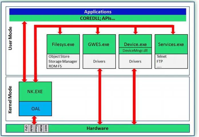
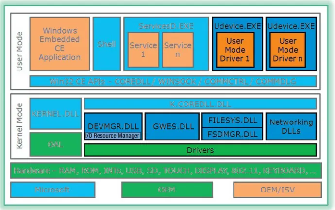
Windows Embedded CE 6.0 (henceforth Windows CE 6.0 for brevity) and later versions are based on the monolithic kernel architecture. Figure 1-2 shows the Windows CE 6.0 architecture and Windows Embedded Compact 7. What’s particularly important to note in this figure is that the device driver hosts (that is, GWES.dll and DevMgr.dll) are dynamically linked libraries themselves. Componentization is still available to the designer who may add or remove system services as needed.
Figure 1-2. Windows CE 6.0 and Windows Embedded Compact 7 System Architecture
User-Mode versus Kernel-Mode Drivers in the Monolithic Architecture
CHAPTER 1 ■ THE FOUNDATION OF DEVICE DRIVER DEVELOPMENT FOR WINDOWS EMBEDDED COMPACT
5
Windows CE System Architecture and I/O Handling
Windows Embedded Compact 7, as its predecessors Windows CE 6.0, is a commercial embedded Real Time Operating System (RTOS) based on a monolithic kernel. The specific device driver model adopted by the operating system is simple and provides for uncomplicated device driver implementation.
Device Driver-Related System Components
Windows Embedded Compact, like any modern embedded operating system, consists of a variety of system components each with a specific purpose to form a platform with a wide-ranging set of functionality and features. The kernel provides the core operating system services additional services, such as GWES and Device Manager, provide further functionality and interfaces. Figure 1-3 highlights those system components that are particularly important for device driver developers.
CHAPTER 1 ■ THE FOUNDATION OF DEVICE DRIVER DEVELOPMENT FOR WINDOWS EMBEDDED COMPACT
Windows CE relies on the following system components to implement a flexible device driver model:
• GWES.DLL – This is the Graphic Windowing and Events Subsystem, which loads
native device drivers and manages them and their interfaces while loaded. The section “Windows Embedded Compact Device Driver Model” later in this chapter introduces GWES in more detail.
• DEVMGR.DLL – This is the Device Manager, which loads kernel mode stream
interface device drivers. In addition Device Manager tracks interfaces advertised by drivers and supports searches for drivers based on a globally unique identifier (GUID). For details, see the section “Windows Embedded Compact Device Driver Model” later in this chapter.
• I/O Resource Manager – Device Manager includes an I/O Resource Manager to
enumerate a list of available resources from the registry.
• FILESYS.DLL and FSDMGR.DLL – These are the Windows Embedded Compact
file system manager and file system driver manager, which load partition drivers and file system drivers into the Windows CE Storage Manager. You learn more about these types of drivers in Chapter 6 “Understanding Device Driver Types.”
• Networking DLLs – These DLLs enable networking functionality, such as TCP/IP.
Chapter 10 “Network Driver Interface Specification” provides more details about network communication in Windows CE.
• UDEVICE.EXE – This is a user mode process to run device drivers in user mode.
The section “Windows Embedded Compact Device Drivers in Kernel or User Mode” later in this chapter discusses the advantages and disadvantages of running device drivers in user mode in more detail.
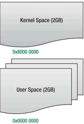
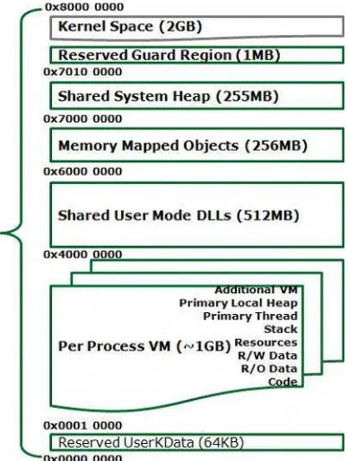
Windows Embedded Compact 7 Memory Architecture
Windows CE 6.0 and Windows Embedded Compact 7 use a Virtual Memory model that divides the address space into separate regions for kernel and user-mode processes (see Figure 1-4). This Virtual Memory model predominantly provides protection to the kernel and for one process from other processes. This is no different than a general purpose OS. However, unlike general purpose OSs, the Virtual Memory model of Windows CE 6.0 and Windows Embedded Compact 7 does not provide a backing store to swap out memory pages.
CHAPTER 1 ■ THE FOUNDATION OF DEVICE DRIVER DEVELOPMENT FOR WINDOWS EMBEDDED COMPACT
7
Figure 1-4. Virtual Memory Model of Windows CE 6.0 and Windows Embedded Compact 7
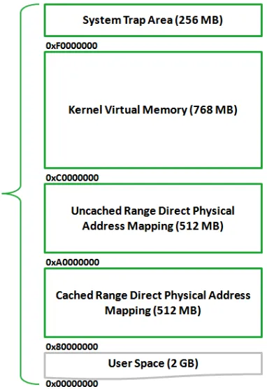
Kernel Space Virtual Memory
Windows CE separates the kernel virtual memory space into separate regions. Figure 1-5 shows how the kernel virtual memory space is structured. New in Windows Embedded Compact 7 is the ability to address physical RAM larger than 512 MBs, up to 3 GBs. However this has to be enabled by the OEM by implementing this support within the OAL. The OEM must describe the extended RAM region within the OEMRamTable structure which defines the additional physical RAM available for any hardware
CHAPTER 1 ■ THE FOUNDATION OF DEVICE DRIVER DEVELOPMENT FOR WINDOWS EMBEDDED COMPACT
Figure 1-5. Kernel Space Virtual Memory Structure
Table 1-1 summarizes the regions in kernel-space virtual memory and describes their purpose.
Table 1-1. Kernel-Space Virtual Memory Regions
Start Address
End Address
Name
Description
xF000 0000 xFFFF FFFF System Trap Area CPU specific VM System call trap area xC000 0000 xEFFF FFFF Kernel VM Virtual memory for the kernel,
CPU-specific. To allow Address Space Layout Randomization
xA000 0000 xBFFF FFFF Static Mapped Uncached Address Space
For access to physical memory bypassing the CPU cache. x8000 0000 x9FFF FFFF Static Mapped Cached
Address Space
CHAPTER 1 ■ THE FOUNDATION OF DEVICE DRIVER DEVELOPMENT FOR WINDOWS EMBEDDED COMPACT
9
User Space Virtual Memory
Windows Embedded Compact separates the user virtual memory space into two main regions for the user process and shared DLLs and memory mapped files. Figure 1-6 shows a schematic structure of the user virtual memory address space.
Figure 1-6. User Space Virtual Memory Structure
CHAPTER 1 ■ THE FOUNDATION OF DEVICE DRIVER DEVELOPMENT FOR WINDOWS EMBEDDED COMPACT
Table 1-2. User-Space Virtual Memory Regions
Start Address
End Address
Name
Description
x7FF0 0000 x7FFF FFFF Reserved guard region Buffer between user and kernel spaces. x7000 0000 x7FEF FFFF Shared system heap Shared heap between the kernel and
processes.
x60000000 x6FFFFFFF Memory mapped objects RAM-backed map files for cross-process communication, expecting all processes to map views at the same virtual address. This is Windows CE shared memory space.
x4000 0000 x5FFF FFFF Shared user-mode DLLs DLLs are loaded starting at the bottom of the stack and moving up.
x0001 0000 x3FFF FFFF Per-process VM Executable code and data. x0000 0000 x0001 0000 Reserved user data Allocated block for user data
Input/Output Handling
Windows Embedded Compact 7 as well as Windows CE 6.0 provides nested interrupts to provide low interrupt latencies and assure minimal latencies for top priority hardware device interrupts. The interrupt model is based on three elements:
• Kernel Interrupt Service Handler – Can handle up to 64 separate hardware IRQ
sources. It determines interrupt priority level and calls an ISR hooked to it and then sets event that is associated with the related Interrupt ID to schedule the associated IST.
• Interrupt Service Routines (ISRs) – The ISR is hooked to a hardware interrupt
request (IRQ) in kernel mode, it acknowledges hardware and determines Interrupt ID. The ISR can be static, that is, built into NK.EXE, or installable (chained in) via kernel call.
• Interrupt Service Threads (ISTs) – The IST performs device-specific servicing for
the specified Interrupt ID and must signal completion of interrupt processing to the hardware.
Interrupt Processing
CHAPTER 1 ■ THE FOUNDATION OF DEVICE DRIVER DEVELOPMENT FOR WINDOWS EMBEDDED COMPACT
11
Figure 1-7. Interrupt Processing in Windows CE
As visualized in Figure 1-7, the process of handling an interrupt is handled in five steps:
1. Device raises registered hardware interrupt
2. Kernel gets exception, calls associated Interrupt Service Routine (ISR)
3. ISR quickly deals with pending interrupt
4. IST in driver is signaled to process interrupt
5. IST completes processing
ISRs and ISTs
ISRs and ISTs work together to perform the necessary Input/Output operations with minimal impact on other processing tasks and to prevent the loss and delay of high-priority interrupts. This interaction is mainly a task of coordinating thread execution between ISR and IST. ISRs and ISTs always work in pairs - the ISR identifies and masks interrupt quickly while the IST handles the bulk of the work and re-enables interrupts as soon as possible.
The interaction between ISR and IST involves the following steps:
1. The IST creates an Event Object mapped to the related SYSINTR ID. The Event Object is a kernel resource on which a WaitForSingleObject function call can wait and exit after the Event Object becomes signaled. The SYSINTR ID identifies the Event Object.
CHAPTER 1 ■ THE FOUNDATION OF DEVICE DRIVER DEVELOPMENT FOR WINDOWS EMBEDDED COMPACT
3. The IST blocks on the event with a WaitForSingleObject function call until the Kernel Interrupt Service Handler sets the related event, thus unblocking the IST.
4. When unblocking the IST, if the IST is the highest priority runnable thread, it will be scheduled to run immediately.
Installable ISRs and Interrupt Sharing
Installable ISRs allow multiple devices to share interrupts and to share a single hardware platform interrupt request (IRQ). Essentially, shared interrupts trigger one interrupt line that is shared by more than one IRQ. For the operating system to handle these IRQs, there must be multiple ISRs chained to handle the shared interrupt. Each ISR, in turn, determines if it owns the interrupt and if so returns the related SYSINTR ID to unblock its associated IST.
Figure 1-8 illustrates how Installable ISRs can share an interrupt to support multiple peripheral devices.
Figure 1-8. Shared Interrupts Using Chaining
An Installable ISR is implemented in a DLL. A device driver can load the ISR into the kernel at runtime by using the LoadIntChainHandler function. The interrupt handler is unloaded by using the FreeIntChainHandler function. Chapter 8 “Device Driver I/O and Interrupts” provides more details about the use of LoadIntChainHandler and FreeIntChainHandler in a device driver.
Windows Embedded Compact Device Driver Model
Windows Embedded Compact 7 implements a simple device driver model that distinguishes between native and stream interface device drivers.
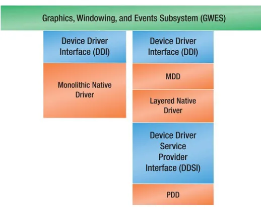
Native Windows CE Device Drivers
CHAPTER 1 ■ THE FOUNDATION OF DEVICE DRIVER DEVELOPMENT FOR WINDOWS EMBEDDED COMPACT
13
Figure 1-9. Native Device Driver Model Interface
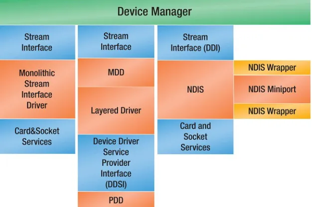
Stream Interface Device Drivers in Windows Embedded Compact
The term Stream Device Driver can be misleading as it is often used for peripheral I/O hardware that processes a stream of data such as serial port device drivers. It might suggest that this type of device driver is not the right choice for block devices that refer to hardware managing chunks of data such as storage disks. However, stream interface device drivers in Windows Embedded Compact handle stream devices as well as block devices. For this reason, I strongly recommend using the term stream interfacedevice driver, which means that the device driver has to expose a defined set of functions that allows applications to communicate with the device driver via the file system API.
CHAPTER 1 ■ THE FOUNDATION OF DEVICE DRIVER DEVELOPMENT FOR WINDOWS EMBEDDED COMPACT
Figure 1-10. Stream Interface Device Driver Model Interface
Device Manager loads kernel mode stream device drivers and manages them and their interfaces while loaded. When the Device Manager loads, it initially loads the I/O Resource Manager to enumerate a list of available resources from the registry. In addition Device Manager tracks interfaces advertised by drivers and supports searches for drivers based on a globally unique identifier (GUID). The section “Loading and Unloading Device Drivers” later in this chapter provides more details about the load process for stream interface device drivers.
Monolithic and Layered Device Drivers
Both native and stream drivers can use either the monolithic or layered driver design as illustrated in Figures 1-9 and 1-10 in the previous sections. A monolithic driver relies on a single DLL to implement both the interface to the operating system and applications, and the logic to the hardware, while the layered driver architecture is based on model device driver (MDD) and platform device driver (PDD).
Monolithic and layered device drivers have the following advantages and disadvantages:
• Monolithic device drivers – Monolithic drivers might be the right choice if you
want to avoid the additional function calls between MDD and PDD for performance reasons.
• Layered device drivers – The layered architecture based on MDD and PDD is
CHAPTER 1 ■ THE FOUNDATION OF DEVICE DRIVER DEVELOPMENT FOR WINDOWS EMBEDDED COMPACT
15
Windows Embedded Compact Device Drivers in Kernel or
User Mode
Because Windows Embedded Compact is now a monolithic kernel architecture device drivers now can either be in kernel mode or in user mode. In kernel mode, device drivers have access to kernel resources. This presented security risks and has lead to a new type of device driver – user mode device drivers. Kernel mode device drivers are managed by Device Manager server library DEVMGR.DLL while user mode device drivers reside each in a user mode process named UDEVICE.EXE however still managed by Device Manager.
Kernel Mode Device Drivers
In Windows Embedded Compact kernel mode means access to kernel address space. However it has to be noted that when a user mode thread makes a system API call, since almost all system APIs are implemented in server libraries running in kernel mode thus the user mode thread runs in kernel mode. This has some bearing on kernel mode device drivers. If a kernel mode device driver receives a pointer to a user mode callback function, without the proper precaution such a callback function can access kernel mode calls and addresses even though it runs in a user mode thread. The proper precautions will be discussed later on in the book.
Kernel mode device drivers are practically the same implementation wise as they were in previous versions of the OS, however the user mode device drivers do not have access to kernel data structures and resources and are hosted in special user mode processes that are created and communicate with a kernel reflector service to provide a secure method for the user mode device driver to perform their tasks.
Kernel mode device driver are loaded into the kernel by either Device Manager or GWES, depending on their interface. Stream device drivers are loaded by Device Manager, DEVMGR.DLL and are managed by it. Native device drivers load into Graphic Windowing and Events subsystem, GWES.DLL. Kernel mode device drivers have full access to kernel data structures and kernel memory. Kernel mode device drivers link to KCOREDLL which is the kernel version of COREDLL to provide access to APIs.
User Mode Device Drivers
CHAPTER 1 ■ THE FOUNDATION OF DEVICE DRIVER DEVELOPMENT FOR WINDOWS EMBEDDED COMPACT
Loading and Unloading Device Drivers
Native and stream drivers only differ in terms of the APIs they expose. You can load both types of drivers during system startup or on demand. However, exactly how Windows Embedded Compact loads a device driver depends on the driver type.
Loading Stream Interface Device Drivers
Device Manager loads kernel mode stream device drivers and manages them and their interfaces while loaded. The Device Manager is a system server dynamically linked library named (DEVMGR.DLL) and is loaded by the kernel at boot time. Once loaded it runs continuously and it loads kernel mode stream device drivers and manages them and their interfaces while loaded. When the Device Manager loads, it initially loads the I/O Resource Manager to enumerate a list of available resources from the registry. In addition Device Manager tracks interfaces advertised by drivers and supports searches for drivers based on a globally unique identifier (GUID). The IClass interface can associate an interface GUID with the driver's legacy name, its $device name, or its $bus name. For example, COM1:, $device\com1, or $bus\pci_0_3_0.
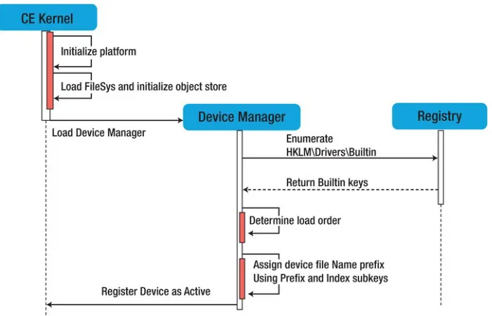
Device Manager Architecture
Device Manager searches the HKLM\Drivers\ Drivers\BuiltIn registry key to determine the key to begin the driver loading process. Device Manager calls ActivateDeviceEx API to load the driver specified by the
Dll subkey value found in the key specified by the Drivers\BuiltIn value. The Dll subkey value is by default BusEnum.dll, also referred to as the bus enumerator. Loading BusEnum.dll causes all device drivers to load. A device loaded by ActivateDeviceEx can read its activation handle from its Active
registry key. Device Manager controls the Active key in the registry. Only Device Manager should access the Active key for read or write access. Device Manager uses the Active and BuiltIn subkeys of the
CHAPTER 1 ■ THE FOUNDATION OF DEVICE DRIVER DEVELOPMENT FOR WINDOWS EMBEDDED COMPACT
17
Figure 1-11. Device Driver initialization during system boot
Device Manager Registry Keys
The HKLM\Drivers\Active registry key contains currently active device drivers that Device Manager loaded. Device driver routines should not modify the Active key nor rely on any specific values within the Active key. When a driver is loaded, Device Manager passes the path to the driver's Active key with the dwContext parameter to the initialization routine. The initialization routine may read and create new values in the Active key; however, it is not allowed to access the key after the initialization function returns.
Device File Names
Applications can access device drivers through file system functions, for example CreateFile to get a handle to a device driver, and using this handle to perform I/O requests such as read, write or perform more elaborate I/O operations via I/O control requests. When calling a file system API such as CreateFile the first parameter it requests is a file name. A device driver’s namespace is used instead of a file name as such. A device driver’s name space can be one of the following formats:
• Three-letter prefix, followed by a number between 0 and 9, followed by a colon.
For example “TST0:”
• $bus mount point, followed by the bus name, bus number, device number, and
CHAPTER 1 ■ THE FOUNDATION OF DEVICE DRIVER DEVELOPMENT FOR WINDOWS EMBEDDED COMPACT
• $device mount point, followed by a three-letter prefix representing the device,
followed by a number, this allows for more than 10 device instances for the same device prefix. For example “\$device\TST0”
Device File Name Prefixes
The prefix consists of three uppercase letters that identify the device file name corresponding to a particular stream interface. The prefix is stored in a registry value called Prefix. When implementing the stream interface, typically the three-letter prefix is designated. Chapter 3 provides an incisive discussion on this subject.
First, the prefix identifies all possible device file names that can access the stream interface driver. Second, the prefix tells the operating system what entry-point file names to expect in the stream
interface DLL. For example, to implement a device driver for a PC Card pager, the PGR indicating PAGER as the three-letter prefix, which in turn would dictate entry-point names, such as PGR_Init,
PGR_IOControl, and so on.
Device File Name Indexes
The index differentiates devices with the same prefix that the stream interface manages. The index is the digit that follows the prefix. By default, Device Manager indexes logically from 1 through 9, with 1 corresponding to the first device file name. If a tenth device file name is required, the index 0 is used.
If device file names starting index need to be other than 1, a starting index in a registry value called
Index within the registry key is specified. This is often necessary if a stream interface driver serves a device that uses a common prefix, such as COM. For example, “COM1:”, “COM2:”, and “COM3:” usually correspond to built-in serial port hardware. However if a driver is for a serial device, such as a packet-radio modem, it should appear as a COM port because modem software often assumes that modems are connected to COM ports. Thus an Index value of 4 is specified to differentiate this packet-radio modem device from the built-in serial devices.
Device Manager can register only one device file name, so if the Index value is specified, rather than letting Device Manager assign indexes, this device driver will support only one device.
I/O Resource Manager
When the OS boots, the bus enumerator enumerates the registry and loads all the built-in devices based on registry information. The I/O Resource Manager then tracks the current state of resources available in the system and manages all further I/O resource requests and allocations by bus drivers. Therefore, bus drivers should request I/O resources from the I/O Resource Manager when they load a client driver for installable devices or other types of devices.
The I/O Resource Manager is an intrinsic part of Device Manager. The I/O Resource Manager tracks the available system resources initialized from the registry before any devices are loaded. Tracking these resources prevents accidental collisions when more than one device driver attempts to employ the same resources.
CHAPTER 1 ■ THE FOUNDATION OF DEVICE DRIVER DEVELOPMENT FOR WINDOWS EMBEDDED COMPACT
19
Every hardware platform has unique IRQs and I/O space available. IRQs for built-in and fixed devices are mapped to interrupt identifiers (SYSINTRs) in the OAL. The IRQs for built-in and fixed devices should be excluded from the available resources. IRQs used with the PCI bus are usually shared.
IRQs and I/O space resources are predefined in HKLM\Drivers\Resources\IRQ and
HKLM\Drivers\Resources\IO registry keys which provide the initial state of the I/O Resource Manager.
Chapter Summary
C H A P T E R 2
The Tools of the Trade
“Tools of trade” is a term utilized in bankruptcy law to establish what assets a person would commonly use for the purpose of making a living. To make a living as device driver developers, our “Tools of trade” are VS2008, Platform Builder (PB), and third-party tools.
Visual Studio with Smart Device support only allows you to develop applications for devices. For Windows Embedded Compact 7 (and previous versions) device driver development, Platform Builder is an absolute must. Platform Builder provides you with the device driver development kit (DDK) and the ability to build an operating system image for testing the device driver. Moreover Platform Builder provides you with the build tools necessary to build device drivers for Windows Embedded Compact 7 (CE), such as setting the build environment variables and debugging and testing tools such as kernel debugger tool and an extensive set of remote tools.
Visual Studio and Platform Builder provide a solid foundation for development, still third-party tools are available to speed up the process of creating a device driver. Two tools that device driver developers should find particularly useful are TRACE32 JTAG debugger, and the Windows CE Device Driver Wizard. This chapter provides an overview of these tools and later chapters will provide in-depth discussion and examples how to use these tools.
In this chapter:
• Visual Studio 2008 • Platform Builder
• Windows CE Build System
• The Device Driver Development Kit • TRACE32
• The Windows CE Device Driver Wizard
Visual Studio 2008
CHAPTER 2 ■ THE TOOLS OF THE TRADE
22
environment for developing OS images, subprojects, downloading the OS images to the target device and debugging capabilities all in one development tool. What is of interest to Windows Embedded Compact developers and device driver developers for this OS is the integration of Platform Builder into Visual Studio 2008 and less Visual Studio as a general developer tool.
Visual Studio 2008 and Platform Builder IDE
Platform Builder for Windows Embedded Compact 7 IDE is integrated into Visual Studio 2008. It provides the user a graphical user interface to create OS designs, connect and download OS images to target devices, a graphical interface to the kernel debugger, edit source code build subprojects, BSP components, and many more capabilities. The build results are the same results as if using command line tools to perform all development efforts, moreover results are interchangeable, meaning that you can interchange command line development and IDE development.
After installing Platform Builder, Visual Studio has specific Windows Embedded Compact related UI components, including a specific device-related menu called the “Target” menu; OS design-specific “Build” menu options; and three new “Tools” sub menus “Platform Builder,” “Windows Embedded Silverlight Tools,” and “Remote Tools.” The main feature however is the Platform Builder wizard and under the “Other Languages ➤ Visual C#” project types the “Remote Tools Framework” wizard. Figure 2-1 shows the Platform Builder Wizard in the “Project Types” tree.
CHAPTER 2 ■ THE TOOLS OF THE TRADE
At the same time the new window called “Catalog Items View” is added and can be found under the “View ➤ Other Windows” menu. The OS design wizard will ask for a BSP on which the OS design is built, and offer a set of jumpstart OS design templates from which to choose. Figures 2-2 and 2-3 describe these steps. Selecting a Board Support Package (BSP) is of the utmost importance when creating a new OS design; however, it is not difficult to add another BSP to the newly created OS design later if the need arises to run the exact same operating system image on another device using a different architecture.
Figure 2-2. BSP selection for the new OS design
Once the OS design is created you can add or remove OS components or BSPs from this OS design using the “Catalog Items View” as shown in Figure 2-4. The Solution Explorer allows access to
CHAPTER 2 ■ THE TOOLS OF THE TRADE
24
Figure 2-3. Selecting a jumpstart design template
CHAPTER 2 ■ THE TOOLS OF THE TRADE
Figure 2-5. The Solution Explorer
Remote Tools
The remote tools that are installed with Visual Studio 2008 with smart device development option selected are designed mainly to help with application development. The main tools of interest to the device driver developer are the Remote Registry Editor and Heap Walker Display. The following is a list of remote tools available with Visual Studio.
• Remote File Viewer - View and manage the file system on a target device
(including exporting and importing)
• Heap Walker Display - Display information about heap identifiers and flags for
each process running on a target device
• Remote Process Viewer - Remote information about each process running on a
target device
CHAPTER 2 ■ THE TOOLS OF THE TRADE
26
• Remote Spy - Display messages received by windows associated with applications
running on a target device
• Remote Zoom-in - Capture a screen image in bitmap (.bmp) file format from a
target device
Remote Tools Framework
The remote tools framework is installed with Platform Builder 2008 and is a development SDK that spans both device side and development workstation plug-in libraries to create a custom remote tool and a remote tool shell to host the custom plug-in. Developing a remote tool involves creating a device side console application that can either push data or respond to requests from the custom remote tool on the development workstation, and of course developing the custom remote tool plug-in. You have a choice to develop the device side application either using a native API, or a .NET compact framework managed API. Although a native client side remote tool application will serve well a device that needs real-time determinism and thus does not support the .NET compact framework, a managed device side application has the advantage of rapid development. The plug-in side is developed using the .NET framework and installs into Visual Studio a remote tools frame wizard to ease the development. An example of such a custom remote tool will be discussed later in the chapter dealing with debugging and testing.
■
Note
Previous versions of Windows CE: In the case of Windows CE 6.0 you have to install Visual Studio 2005
and then install platform Builder 6.0. Prior to Windows CE 6.0 Platform Builder IDE was a standalone tool and did
not require Visual Studio.
Platform Builder
Platform Builder is the tool you use to develop and build operating system designs based on your choice of hardware. An operating system design is composed of all the systems components that the developer chooses out of the catalog to incorporate in his/her operating system. To allow this, Platform Builder has all the operating systems components within Platform Builder’s directory structure.
Platform Builder Directory Tree
All the necessary files and tools that are needed to create a Windows CE operating system image are collected under a directory hierarchy located on the installation disk. For Windows CE 7.0 the OS installation root directory is WINCE700, this directory is referred to by the build environment variable
%_WINCEROOT%. For example, it would typically be set to C:\WINCE700 where ‘C:’ is the installation disk. Under this folder you should find the following five folders:
CHAPTER 2 ■ THE TOOLS OF THE TRADE
• SDK Directory • Others Directory • Private Directory
When a new OS design is created for the first time a new folder will be created: OOSDesigns. See Figure 2-6.
Figure 2-6. Platform Builder Folder Hierarchy
Platform Builder subdirectories that are most relevant to device driver developers are PLATFORM and PUBLIC subdirectories, because these contain device driver source code which is separated into specific board dependent drivers, system-on-chip (SOC) drivers, and common drivers.
• Specific board (BSP) dependent device driver source code is located under
%_WINCEROOT%\PLATFORM\%_TGTPLAT%\SRC\DRIVERS directory
• System on Chip device driver source code is located under
%_WINCEROOT%\PLATFORM\COMMON\SRC\SOC
• SoC device drivers handle peripheral I/O devices that are integrated on the
CPU chip to form the SoC.
• Common source code for device drivers that is supplied by Microsoft is located
CHAPTER 2 ■ THE TOOLS OF THE TRADE
28
• Source code for common drivers for non-native peripheral devices. The source
code for these device drivers is platform-independent code and is not specific to a hardware platform or CPU architecture and is located under
%_WINCEROOT%\PUBLIC\COMMON\OAK\DRIVERS
PLATFORM Directory
This directory is the root directory for the board support packages (BSPs) that were installed with Platform Builder. Each such BSP is located in its own directory hierarchy with the top folder named to reflect the hardware it supports. Another extremely important subdirectory within the PLATFORM directory tree is the COMMON subdirectory which contains OEM adaptation layer source code, including routines that are generic to all BSPs and routines that are specific to certain architecture.
PUBLIC Directory
This directory contains a platform-independent set of components and configurations. The
subdirectories in the PUBLIC directory that contain modules and components have the same name as Windows CE 7.0 modules. It contains three types of subdirectories:
• Module and component subdirectories • Reference configuration subdirectories • Custom configuration subdirectories
Platform Builder IDE
Platform Builder Integrated Development Environment (IDE) is a graphical user interface contained within Visual Studio 2008 and consists of an integrated set of tools, context-sensitive menus, toolbars, and shortcut keys, that enable you to create, test, and refine OS designs and Catalog items.
Platform Builder Wizards
Platform Builder provides a set of wizards in the IDE that enable you to create OS designs and subprojects.
Windows CE OS Design Wizard
CHAPTER 2 ■ THE TOOLS OF THE TRADE
■
Note
Design Templates: Design templates provide examples of how to develop an OS for a specific device
category and can help reduce your overall OS development time. These are XML files that include the basic
building blocks of the operating system with a variety of components that make up a device category, including an
industrial controller.
Windows CE Subproject Wizard
The Windows CE Subproject Wizard will conduct you throughout the process of creating a subproject that you can use to develop items based on your OS design, including applications, dynamic-link libraries (DLLs), static libraries, and a TUX test harness. The resulting subproject is added to the currently active OS design. Because subprojects depend on the specific OS design that contains them, they are built only in the context of that specific OS design.
Platform Builder Remote Tools
The remote tools that are installed with Platform Builder are an invaluable set of software tools that help you as a device driver developer connect and remotely monitor information and test your creation. These tools are divided into two groups: tools for debugging and testing, and tools for information management. In the second group, the most relevant tool is the Remote Registry Editor. Checking the active device driver node in the registry is the surest way to ascertain that your device driver was loaded by Device Manager. In the first group the most helpful tools are the Remote Kernel Tracker and Remote Call Profiler. The first helps to track interrupts, and synchronizes object triggering and thread execution for your device and the second helps you create efficient code by detecting coding bottlenecks.
Platform Builder Registry Editor
CHAPTER 2 ■ THE TOOLS OF THE TRADE
30
Figure 2-7. An example of a device driver registry entry in registry editor RegEdit view
The Build System
Building software amounts to the process of going from source code to a binary executable so that this executable runs and performs its functionality. To accomplish these tasks a set of tools, executables, and scripts are provided to perform an automated build using one command. Understanding the build process is detrimental to the development of device drivers for Windows CE.
Overview
CHAPTER 2 ■ THE TOOLS OF THE TRADE
There are four phases to the build process:
• Compile phase – source code and resource files are compiled and linked to
generate executables, libraries, and binary resource files for the selected locales. It is seldom required to rebuild operating system components because binaries are already provided by Microsoft.
• Sysgen phase - SYSGEN variables are set or cleared based on the catalog items and
dependency trees included in the OS design. It then filters the header files and creates import libraries for the Software Development Kits (SDKs) defined in the OS design, creates a set of run-time image configuration files for the OS design, and builds the specific BSP.
• Release copy phase - all files required to create the run-time image are copied to
the OS design’s release directory.
• Make run-time image phase - project-specific files such as Project.bib and
Project.reg are copied to the release directory and based on environment variables specified in .reg and .bib files creates the final run-time image in the release directory. Configuration files are merged for example registry configuration files are merged into reginit.ini to be compiled into the image registry file. OS image localization is performed during this final phase of image creation.
The Build Tools
CHAPTER 2 ■ THE TOOLS OF THE TRADE
32
Figure 2-8. OS image build phases and corresponding build tools
Command line build
The command line build uses the build demo tool to jumpstart the whole build process. Build demo tool is a batch file that calls the master build tool cebuild.bat and when the first two phases are done it calls buildrel.bat and makeimage.exe to complete the build. You should be aware that Platform Builder IDE calls builddemo.bat with arguments as designated by the menu items that are selected by the user. Platform Builder documentation does a good job detailing all the possible options. You should review builddemo.bat as it is self-documented with good comments.
Understanding the SYSGEN process
CHAPTER 2 ■ THE TOOLS OF THE TRADE
SYSGEN Filtering
Filtering is done using @CESYSGEN comment tags to filter files based on component settings and is run from inside %__PROJROOT%\CESYSGEN\MAKEFILE. Filtering creates tag variables based on
xxx_MODULES and yyy_COMPONENTS variables and generates CECONFIG.H for use with C pre-processor.
For example:
EXAMPLE_MODULES=ExmpleDLL
EXAMPLEDLL_COMPONENTS=Exmpl1 Exmpl2
generates:
EXAMPLE_MODULES_EXAMPLEDLL EXAMPLEDLL_EXMPL1
EXAMPLEDLL_EXMPL2
Environment variables and DEPTREES
An environment variable contains information about an aspect of the OS design and should not to be confused with System Variables, which help filter the selected functionality of an OS design. _DEPTREES which is the environment variable that controls pre-sysgen phase and depicts the OS dependency tree. It is used by cebuild.bat that performs pre-sysgen build and sysgen. It uses _DEPTREES environment variable to determine what to build/sysgen. You can add your own folder hierarchy to the DEPTREES environment variable for example this is how the PRIVATE folder is added to the DEPTREES:
:AddDepTree
if EXIST %_WINCEROOT%\private\%1 set _DEPTREES=%_DEPTREES% %1 goto :EOF
There are four groupings of environment variables
• BSP Environment Variables - define the level of optional support available with a
board support package.
• BSP_NO Environment Variables - define the level of optional support available
with a hardware platform.
• IMG Environment Variables - remove modules from your OS design, but leave the
associated registry entries in your design intact.
• Miscellaneous Environment Variables
The Master Build Tool
The Master Build Tool (Cebuild.bat) builds the modules and functionality and generates the source code for an entire OS design. Cebuild.bat performs the following steps to create a run-time image:
CHAPTER 2 ■ THE TOOLS OF THE TRADE
34
For each project specified by the _DEPTREES environment variable, Cebuild.bat runs Sysgen.bat –p Tree, where Tree is a project specified by _DEPTREES. Sysgen.bat builds the project's modules, which are selected in Cesysgen.bat. Sysgen.bat builds the modules in the %_PROJECTROOT%\Oak\Misc directory.
Cebuild.bat runs Build.exe in the %_PLATFORMROOT%\%_TGTPLAT% directory to compile the code for the hardware platform.
How to Prepare Your Development Environment
Windows Embedded Compact Build Environment tool WINCE.BAT is the tool that prepares the build environment. It uses three input parameters to set environment variables. The first parameter indicates the CPU architecture for the build and sets the %_TGTCPU% environment variable; the second
parameter indicates the OSDesign directory name for the build and sets the %_TGTPROJ% environment variable and last parameter indicates the BSP being used for the build to set the %_TGTPLAT%
environment variable. Once you have prepared the build environment, you are ready to build your device driver. You will use the build tool, Build.exe for the actual build.
Build.exe
For device driver developers the most significant procedure of the build process is building the source code of the device driver. Build.exe is the tool that performs this task. Build.exe activity is described in the diagram in Figure 2-9 and the following steps:
1. Build.exe looks for a DIRS file in the current directory; then, if the DIRS file exists, the file directs Build.exe to additional subdirectories that contain source code or additional DIRS files.
2. If there is no DIRS file in the current directory, Build.exe searches for a SOURCES file.
CHAPTER 2 ■ THE TOOLS OF THE TRADE
Figure 2-9. Build.exe activity flow
DIRS Files
A DIRS file is a text file that lists subdirectories containing other DIRS or SOURCES files. The following example shows a DIRS file that lists the device drivers to be built for to the VirtualPC BSP. When build.exe evaluates this file, it will traverse the ISR_VPCMOUSE, KEYBD, NDIS_DC21X4, and
WAVEDEV2_SB16 directories looking for SOURCES file or another DIRS file. The DIRS directive orders the build sequence, so in the following example the build.exe will traverse the directory three starting with wavedev2_sb16 and so on. It is possible to use the wild card sign * in a DIRS file to traverse the entire set of subdirectories but this would not be an ordered sequence.
DIRS= \
wavedev2_sb16 \ ndis_dc21x4 \ keybd \ isr_vpcmouse \
SOURCES Files
CHAPTER 2 ■ THE TOOLS OF THE TRADE
36
This allows the component makefile to remain relatively simple. The shared system makefile is included by a simple one line makefile in the component subdirectory.
!INCLUDE $(_MAKEENVROOT)\makefile.def
Makefile.def provides default MAKE rules for most aspects of the build and provides standard rules for various types of targets thus reduces amount of MAKEFILE script needed for each project. Located in
%_WINCEROOT%\public\common\OAK\misc. An example of a SOURCES file for the VirtualPC mouse ISR is a non-complicated example of the makefile macro definition directives involved. For example
TARGETLIBS macro definition directive specifies additional library files that should be linked into the target executable. Platform Builder documentation is a good reference for the various macro definition directives that are used by NMAKE utility.
TARGETNAME=isr_vpcmouse RELEASETYPE=PLATFORM TARGETTYPE=DYNLINK DLLENTRY=DllEntry TARGETLIBS= \
$(_COMMONSDKROOT)\lib\$(_CPUINDPATH)\coredll.lib \ SOURCES=isr_vpcmouse.c
Figure 2-10 describes how the complete project makefile is composed using SOURCES file and the makefile.def file. The makefile is then processed by the NMAKE utility to compile and link the project’s source code files and dependent libraries into a target executable.
Figure 2-10. Inserting the project SOURCES file directives into a makefile
SOURCES.CMN
Sources.cmn is a text file that provides a place to store common settings that apply to the entire source tree. It is located at the topmost directory of the sources directory tree where the topmost DIRS file is located. The following example is of the Sources.cmn file for the VirtualPC BSP.
WINCEOEM=1 IMGNODFLTDDK=1 WARNISERROR=1 RELEASETYPE=PLATFORM
CHAPTER 2 ■ THE TOOLS OF THE TRADE
_PLATCOMMONLIB=$(_COMMONPUBROOT)\platcomm\$(_TGTPLAT)\lib _PLATLIB=$(_COMMONPUBROOT)\platform\$(_TGTPLAT)\lib
_OEMINCPATH=$(_WINCEROOT)\public\common\sdk\inc
_OEMINCPATH=$(_OEMINCPATH);$(_WINCEROOT)\public\common\oak\inc _OEMINCPATH=$(_OEMINCPATH);$(_WINCEROOT)\public\common\ddk\inc
_ISVINCPATH=$(_WINCEROOT)\public\common\sdk\inc
INCLUDES=$(_TARGETPLATROOT)\src\inc
INCLUDES=$(INCLUDES);$(_WINCEROOT)\platform\common\src\soc\x86_ms_v1\inc INCLUDES=$(INCLUDES);$(_PLATFORMROOT)\common\src\x86\inc
INCLUDES=$(INCLUDES);$(_PLATFORMROOT)\common\src\inc
Creating Command Line Build Batch Files
When developing device drivers, using command line build is extremely quick and efficient. It is very easy to prepare batch files to set up the command line build environment and run the build from a command line prompt window. First you have to setup your environment, the following example sets up the build environment for building projects for x86 architecture, using the VirtualPC BSP. Because I may create various environment batch files, I would name this file VPCENV.BAT.
echo on
set _WINCEROOT=C:\wince700
cd %_WINCEROOT%\public\common\oak\misc call Wince.bat x86 CEBASE VirtualPC set WINCEDEBUG=debug
This batch file sets up everything we need to build a device driver that will be incorporated on an operating system running on a virtual PC device. Figure 2-11 shows the result of running this
environment batch file.