TA30
Articulated Dumptruck
Maintenance Manual
TECHNICAL PUBLICATIONS DEPARTMENT TEREX EQUIPMENT LIMITED MOTHERWELL, SCOTLAND ML1 5RY REF. NO. SM 799
CLICK HERE FOR TABLE OF CONTENTS
CLICK HERE TO RETURN TO MAIN LIBRARY INDEX
TEREX SERVICE DEPARTMENT
PURPOSE:To advise potentially hazardous condition. DETAIL:
It has been brought to our attention that 'Viton' material used in manufacture of oil seals and 'O' rings, produces a highly corrosive acid (Hydrofluoric) when subjected to temperatures above 315° C.
The resulting contamination can have extreme consequences on human tissue since it is almost impossible to remove after contact.
We therefore recommend the following procedure when it is necessary to inspect any equipment that has been subjected to a high temperature i.e. fire.
a. Visually inspect for any gaskets or seals which have suffered from heat; they will appear black and sticky. b. If this is affirmed - Do Not Touch
c. Make enquiries to ascertain the material composition. Any Fluoro-elastomer (Viton, Fluorel or Tecmoflon) should be considered dangerous but natural rubber and nitrile are non-hazardous.
d. If Fluoro-elastomer seals have been used, then the affected area MUST be decontaminated before undertaking further work.
e. Disposable Heavy Duty Gloves (Neoprene) MUST be worn and the affected area decontaminated by washing thoroughly with Limewater (Calcium Hydroxide solution).
f. Any cloths, residue and gloves used MUST be safely discarded after use.
Note: Burning of the discarded items is NOT RECOMMENDED, except in an approved incineration process where the gaseous products are treated by alkaline scrubbing.
Service
Information
Alert
DATE: April 1994 B168
MODEL: General
SUBJECT: VITON 'O' RINGS AND SEALS (FLUORO-ELASTOMERS) - SAFETY HAZARDS
TEREX Equipment Limited, Motherwell, Scotland ML1 5RY Tel. (0698) 732121 Tlx. 77141 Fax. (0698) 734046
The information contained within this Alert must not be made available to third parties not authorised to receive it.
Proper service and repair is important to the safe, reliable operation of all motor vehicles. The service procedures recommended and described in this publication, are effective methods for performing service operations. Some of these service operations require the use of tools specially designed for the purpose. The special tools should be used when, and as recommended.
It is important to note that this publication contains various WARNINGS and NOTES which should be carefully read in order to minimize the risk of personal injury to personnel, or the possibility that improper service methods will be followed which may damage the vehicle or render it unsafe. It is also important to understand these WARNINGS and NOTES are not exhaustive. It is not possible to know, evaluate and advise the service trade of ALL conceivable ways in which service might be carried out, or, of the possible hazardous consequences of each way. Consequently, no such broad evaluation has been undertaken. Accordingly, anyone who uses a service procedure, or tool, which is not recommended, must first satisfy themselves thoroughly that neither their safety, nor vehicle safety, will be jeopardized by the service method he/she selects.
Two types of heading are used in this manual to attract your attention.
1. WARNING - This symbol is used when an operating procedure, practice, etc., which, if not correctly followed could result in personal injury or loss of life. Look for this symbol to point out important safety precautions. It means - ATTENTION! BECOME ALERT! YOUR SAFETY IS INVOLVED!
2. Note - This is used when an operating procedure, practice, etc., which, if not strictly observed, could result in damage to or destruction of equipment.
IMPORTANT SAFETY NOTICE
WARNING
Never use parts which are altered, modified, or weakened in operation. This can seriously jeopardize the integrity of the machine and could result in property damage or serious personal injury.
SM 1935 Rev 3 10-02
TABLE OF CONTENTS
Section No. Description SM No.
000 GENERAL INFORMATION
0000 Technical Data - TA30 1937 Rev 1
0010 Welding Procedure 2172
100 CHASSIS
0010 Frames 1960 Rev 1
0020 Articulation and Oscillation Pivot - Pre May 2000 Production 1975 0020 Articulation and Oscillation Pivot - From May 2000 Production 1988 Rev 1
0040 Hood and Mounting 1984 Rev 1
0070 Fenders and Mounting 1963
110 ENGINE
0030 Engine and Mounting 1964
0040 Kysor DST Fan 1974
0050 Air Cleaner 1958
120 TRANSMISSION
0010 Transmission and Mounting 1965
130 DRIVELINES
0010 Front and Rear Drivelines 1534 Rev 1
140 FRONT AXLE GROUP
0020 Axle Group (Hub) (Refer to Section 160-0030)
-0040 Wheel Rim and Tyre (Refer to Section 160-0050)
-0060 Differential Drive Head (Refer to Section 160-0020)
-150 CENTRE AXLE
0020 Differential Drive Head 1971
160 REAR AXLE GROUP
0020 Differential Drive Head 1969
0030 Axle Group (Hub) 1968
0050 Wheel Rim and Tyre 1970
165 BRAKE PARTS
0010 Brake Parts - Rear 1962
0020 Brake Parts - Front 1961
170 PARKING BRAKE
0010 Parking Brake and Mounting 1967
180 SUSPENSION SYSTEM 0020 Front Suspension 1979 0021 Air Spring 1480 0022 Levelling Valve 1481 0040 Rear Suspension 1978 190 ELECTRICAL SYSTEM
0000 Circuit Diagrams 1946 Rev 1
0270 Switches and Sensors 1959 Rev 1
200 FUEL SYSTEM
SM 1935 Rev 2 04-02
2
TABLE OF CONTENTS
Section No. Description SM No.
210 COOLING SYSTEM
0000 Cooling System 1983
0040 Radiator, Header Tank and Mounting 1987
0060 Transmission Oil Cooler 1977
0100 Hydraulic Oil Cooler 1976
220 STEERING SYSTEM
0000 Steering System Schematic 1943
0050 Steering Pump (Refer to Section 230-0050)
-0090 Steering Valve 1986 Rev 1
0105 Priority Valve 1947
0120 Steering Cylinder 1955
0140 Emergency Valve 1944
230 BODY SYSTEM
0000 Body System Schematic 1949 Rev 1
0040 Hydraulic Tank 1950
0050 Main Hydraulic Pump 1951
0060 Body Control Valve 1952
0081 Body Control Joystick 1953 Rev 2
0121 Pilot Supply Valve 1954
0130 Body Cylinder 1956
250 BRAKING SYSTEM
0000 Air Braking System Schematic 1948
0000 Hydraulic Braking System Schematic 1982
0070 Treadle Valve 1939
0170 Air Tanks and Mounting 1941
0190 Park Emergency Control Valve 1940
0200 Air Drier 1985 Rev 1
0260 Pressure Converter 1508
0270 Air Breather 1509
0280 Relay Emergency Valve 1945
0290 Pressure Protection Valve (4 way) 1938
260 OPERATORS COMPARTMENT
0010 Cab and Mounting 1957
0090 Driver Seat and Mounting 1981
0130 Air Conditioning 1966
270 BODY
0010 Body and Mounting 1980
300 MISCELLANEOUS
0020 Lubrication System 1972
0070 Service Tools 1973
0080 Axle Bolt and Nut Torque Specifications 1521
0080 Standard Bolt and Nut Torque Specifications 1238
0090 Unit Storage 1239
Section 000-0000
SM - 2476
ENGINE
Make/Model ... Cummins MTA11-C300 Type ... Four cycle, low emission, direct injection diesel, water-cooled, turbocharged and aftercooled. Gross power at 2 100 rev/min ... 224 kW (300 hp, 304 PS) Net power at 2 100 rev/min ... 214 kW (287 hp, 291 PS)
Note: Gross power rated to SAE J1995 Jun 90. Engine
emission meets USA EPA/CARB MOH 40 CFR 89 and EU NRMM (non-road mobile machinery) directive. Maximum Torque ... 1 376 Nm (1 015 lbf ft) at 1 300 rev/min Number of cylinders/configuration ... 6, in line Bore x Stroke ... 125 x 147 mm (4.92 x 5.79 in) Total Displacement ... 10.8 litres (660 in³) Air cleaner ... Dry type, double element Starting ... Electric Maximum Speed (No load) ... 2 450 rev/min Maximum Speed (Full load) ... 2 100 rev/min Idle Speed ... 675/750 rev/min Safe Operating Angle ... 43°/94% Grade
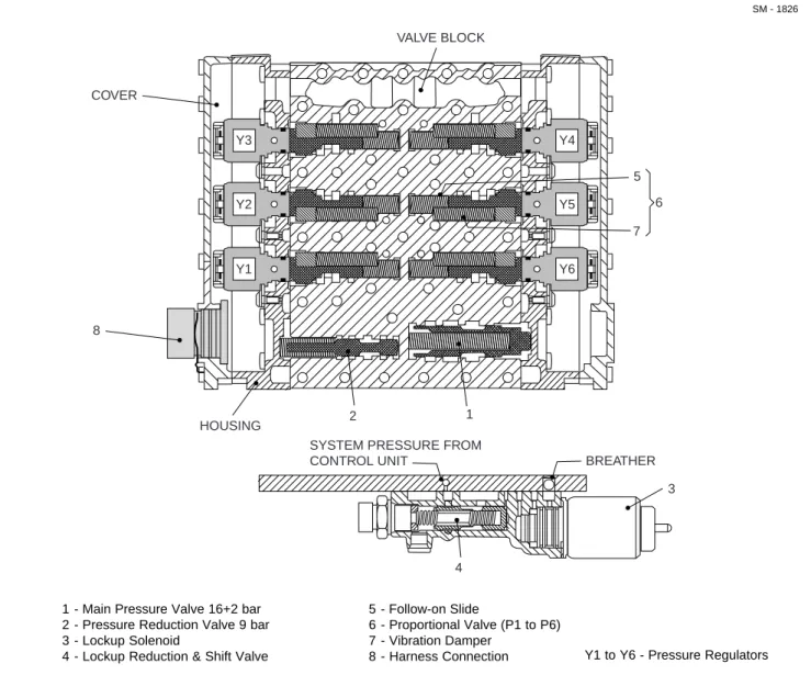
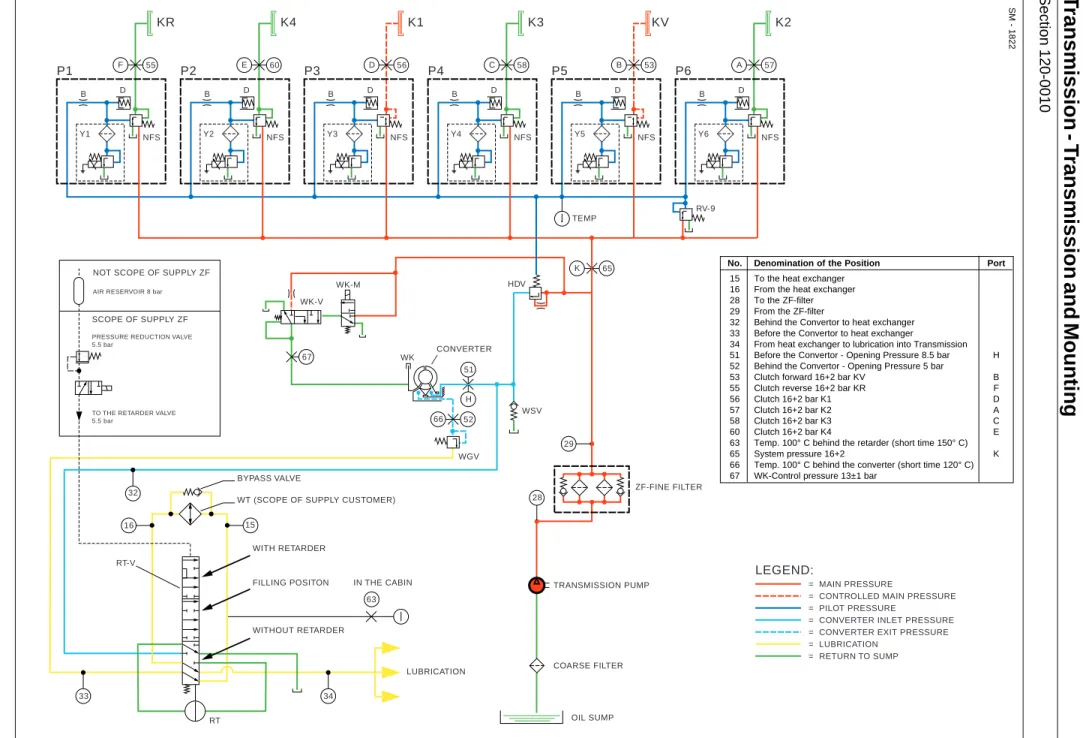
TRANSMISSION
Make/Model ... ZF 6WG 260 II Automatic with manual override. The transmission assembly consists of a torque converter close-coupled to a countershaft-type gearbox with integral output transfer gearing. Automatic shifting throughout the range, with kickdown feature. Lockup action in all forward gears. A torque proportioning output differential transmits drive permanently to front and rear axles. This differential may be locked by the driver for use in difficult traction conditions. Standard integral hydraulic retarder which is automatically operated should the engine
Fig. 1 - Machine Dimensions
overspeed. Blocked filter indicator and filter bypass system provide valve block with additional protection from unfiltered oil.
Pressures:
Main ... 16 + 2 bar (232 + 30 lbf/in²) Lockup (Wk) ... 14 ± 1 bar (190 ± 15 lbf/in²) Converter 'IN' ... 7.6 bar (110 lbf/in2) at 2 300 rev/min
Converter 'OUT' ... 4.8 bar (70 lbf/in2) at 2 300 rev/min
Converter Relief Valve ... 8.5 bar (123 lbf/in2)
Retarder ... 5.5 bar (80 lbf/in2)
Temperatures:
Normal ... 80° - 110° C (176° - 230° F) Maximum ... 120° C (248° F) Stall Speed ... 1 655 ± 50 rev/min Ratios:
Torque Converter ... 1.84:1 Transmission ... Refer to table
Forward Gear 1 2 3 4 5 6 Ratio 5.35 3.45 2.21 1.42 0.97 0.62 km/h 5.0 8.0 12.5 19.5 29.0 45.0 mile/h 3.0 5.0 8.0 12.0 18.0 28.0 Reverse Gear 1 2 3 Ratio 5.35 2.21 0.97 km/h 5.0 12.5 29.0 mile/h 3.0 8.0 18.0
GENERAL INFORMATION - Technical Data
25˚ 2 400 (7-10) 1 260 (4-2) 3 310 (10-10) 1 435 (4-8) Max. Body Depth 3 190 (10-6) 505 (1-8) 2 200 (7-3) 2 820 (9-3) 3 405 (11-2) 45˚ 65˚ 2 820 (9-3) 1 720(5-8) 1 245(4-1) 9 445 (31-0) 660 (2-2) 1 835 (6-0) 2 860 (9-4) 5 885 (19-4) 4 390 (14-5) 4 840 (15-10) Vehicle Clearance Turning Diameter 17.6 m (58-0) 2 615 (8-7) 2 815 (9-3) 1 580 (5-2) Dimensions in mm (ft-in) 30/65 R 25 tyres increase width over tyres to 3 000 mm (9-10)
General Information - Technical Data
Section 000-0000
SM 1937 Rev 1 11-00 2
AXLES
Three axles in permanent all-wheel drive with differential coupling between each axle to prevent driveline wind-up. Heavy duty axles with fully-floating axle shafts and outboard planetary reduction gearing.
Automatic limited slip differentials in each axle. Centre axle incorporates a through-drive differential to transmit drive to the rear axle. Locking of this differential is actuated
simultaneously with the transmission output differential lock.
Ratios:
Differential ... 3.44:1 Planetary ... 6.35:1 Total Reduction ... 21.85:1
SUSPENSION
Front: Axle is carried on the leading arms of a sub-frame
pivoting on the main frame. Suspension is by flexible air bellows with four heavy duty hydraulic dampers.
Axle Vertical Travel ... 127 mm (5 in)
Rear: Each axle is coupled to the frame by three
rubber-bushed links with lateral restraint by transverse link. Pivoting inter-axle balance beams equalise load on each axle. Suspension movement is cushioned by rubber/metal laminated compression units between each axle and underside of balance beam ends.
Axle Vertical Travel ... ± 130 mm (5.12 in) Axle Oscillation ... ± 12°
BRAKES
Air assisted hydraulic dry disc on each wheel with two heavy-duty callipers per disc at the front and a single heavy-duty calliper per disc at the rear. Independent circuits for front and rear brake systems. Overstroke actuates warning light. Brake system meets ISO 3450, SAE J1473.
Air System Pressure ... 7.6 bar (110 lbf/in²) Total Air Reservoir Capacity ... 55 litres (3 356 in³) Hydraulic Brake Fluid Capacity ... 2.64 litres (0.68 US gal)
Parking: Spring-applied, air-released disc on rear driveline.
Emergency: Emergency brake control actuates the service brakes. Automatic application of service brakes should pressure fall in the brake air system.
Retardation: Hydraulic retarder integral with transmission.
WHEELS AND TYRES
Wheels: ... 5-piece earthmover rims with 12 stud fixing Size:
Standard ... 25 x 19.50 in for 23.5 R25** tyres Optional ... 25 x 22.00 in for 30/65 R25** tyres Tyres:
Standard ... 23.5 R25** Optional ... 30/65 R25**
Inflation Pressures (Bridgestone):
Front Rear 23.5 R25** 4.0 bar (58 lbf/in²) 4.8 bar (69 lbf/in²) 30/65 R25** 4.3 bar (62 lbf/in²) 4.3 bar (62 lbf/in²)
Note: Tyre pressures should be regarded as nominal only.
It is recommended that for tyres both listed and unlisted, the user should consult the tyre manufacturer and evaluate all job conditions in order to make the proper selection.
HYDRAULIC SYSTEM Steering and Body Hoist
The steering and body hoist systems are supplied with oil from a common tank by the main hydraulic pump. Gear pump driven from power takeoff on transmission. System components are protected by full flow filtration on the return line.
Pump:
Type ... Gear Capacity at 2 300 rev/min ... 4.49 litre/s (71 US gal/min)
Steering System
Hydrostatic power steering by two single-stage, double-acting, cushioned steering cylinders. Emergency steering pressure is provided by a ground driven pump mounted on the rear of the transmission. An audible alarm and warning light indicates should the emergency system activate. Conforms to ISO 5010, SAE J53.
System Pressure ... 241 bar (3 500 lbf/in²) Steering Angle to either side ... 45° Lock to Lock Turns, steering wheel ... 4 Vehicle Clearance Circle (SAE) ... 17.6 m (58 ft)
Body Hoist System
Two single-stage, double-acting hoist rams, cushioned at both ends of stroke. Electro servo assisted hoist control.
System Pressure ... 221 bar (3 200 lbf/in²) Control Valve ... Pilot Operated, Open Centre Body Raise Time (loaded) ... 12 sec Body Lower Time (power down) ... 7.5 sec
Section 000-0000
General Information - Technical Data
ELECTRICAL SYSTEM
Type ... 24 volt, Negative Ground Battery ... Two, 12 Volt, 143 Ah each Accessories ... 24 Volt Alternator ... 70 Amp
BODY
Of all welded construction, fabricated from high hardness (min. 360 BHN) 1 000 MPa (145 000 lbf/in²) yield strength steel. 25° tail chute angle provides good load retention without tailgate.
Plate Thicknesses:
Floor and Tailchute ... 15 mm (0.59 in) Sides ... 12 mm (0.47 in) Front ... 8 mm (0.31 in)
Volume:
Struck (SAE) ... 13.0 m³ (17.0 yd³) Heaped 2:1 (SAE) ... 16.0 m³ (21.0 yd³)
SERVICE CAPACITIES
Fuel tank ... 330 litres (87 US gal) Hydraulic System
(steering & body) ... 200 litres (52.8 US gal) Engine Crankcase ... 40 litres (10.5 US gal) Cooling System ... 59 litres (15.6 US gal) Transmission & filters (dry fill) ... 52 litres (13.8 US gal) Transmission & filters (wet fill) ... 26 litres (6.9 US gal) Differentials - Front & Rear (each) ... 11 litres (2.9 US gal) Differential - Centre ... 14 litres (3.7 US gal) Planetaries (each) ... 3.5 litres (0.9 US gal) Service Brakes ... 3 litres (0.79 US gal) Air Conditioning Compressor ... 0.125 litres (0.033 US gal)
TYPICAL NOISE LEVELS
Operator Ear (ISO 6394) ... 79 dbA
*Exterior Sound Rating (SAE J88 JUN 86) ... TBA dbA *- The above result is for the mode giving the highest exterior sound level when measured and operated as per the prescribed procedures of the standard. Results shown are for the vehicle in base configuration.
Note: Noise Level Exposure to the operator and bystander
personnel may be higher depending upon proximity to buildings, rock piles, machinery, etc.. The actual job site Noise Level Exposure must be measured and applicable regulations complied with in respect to Employee Hearing Protection. * * * *
Vehicle Weights
Standard Vehicle kg lb Net Distribution Front Axle 10 585 23 335 Centre Axle 5 000 11 025 Rear Axle 4 970 10 955 Vehicle, Net 20 555 45 315 Payload 27 000 59 525 Gross Distribution Front Axle 14 450 31 860 Bogie Axle, leading 16 545 36 470 Bogie Axle, rear 16 560 36 510Vehicle, Gross 47 555 104 840
Bare Chassis 16 025 35 330
Body 4 000 8 820
Section 000-0010
Welding
WARNINGS
Before any welding is done on a machine equipped with any electronic systems, disconnect the following (if applicable) in this order: Battery earth cable, battery supply cable, alternator earth cables, alternator supply cables and electrical connections at the engine ECM, transmission ECU, body control lever, hydraulics ECU and cab bulkhead to avoid damage to electrical components. Turn off battery master switch to isolate the batteries before disconnecting any components.
After welding connect all of the above in the reverse order.
Before any welding is done ensure all paint has been removed from the area to be welded. Failure to do so may result in hazardous fumes being given off from the paint.
Note: Always fasten the welding machines ground cable to the piece/frame being welded if possible. Electric arc welding is recommended for all welded frame repairs. Since the nature and extent of damage to the frame cannot be predetermined, no definite repair procedure can be established. As a general rule however, if parts are twisted, bent or pulled apart, or a frame is bent or out of alignment, no welding should be done until the parts are straightened or realigned. Successfully welded repairs will depend to a great extent upon the use of the proper equipment, materials and the ability of the welder. The Customer Support Department can be consulted regarding the feasibility of welding repairs.
WARNING
Welding and flame cutting cadmium plated metals produce odourless fumes which are toxic. Recommended industrial hygiene practice for protection of the welding operator from the cadmium fumes and metallic oxides requires enclosure ventilation specifically designed for the welding process. A respiratory protective device such as the M.S.A. 'Gasfoe' respirator with G.M.A. cartridge will provide protection against cadmium, fumes and metallic oxides. The 'Gasfoe' respirator has been approved by the U.S. Bureau of Mines: Approval number 23B-10, and is designed to protect against gases, vapours, and/or metal fumes.
Note: The current from the welding rod always follows the path of least resistance. If, for example, the ground clamp is attached to the rear frame when welding is performed on the front frame, the current must pass a frame connection to return to the welding machine. Since the pivot coupling offers the least resistance but not a sound electrical connection, small electric arcs may be set up across the moving parts which may cause welding blotches on their wearing surfaces and increase the wear rate of these components.
General Welding Procedure
The following general procedure should be used for the repair of defects outwith the vicinity of alloy steel castings.
1. Completely ARC-AIR gouge or grind out the crack until sound metal is reached. If ARC-AIR method is employed, pre-heat area to 100° C (212° F), measure 3 - 4" either side of repair prior to gouging. On
completion of gouging grind to remove thin carbon layer.
2. Apply dye-penetrant check to ensure crack has been completely removed.
General Information - Welding Procedure
Section 000-0010
SM 2172 10-02
2
3. Pre-heat area to 100° C (212° F), measured 3 - 4" either side of repair. Avoid local overheating.
4. Weld completely using E-7016 electrodes. Care must be taken to ensure electrodes are protected from moisture pick-ups at all times.
5. Allow repair weld to cool slowly.
6. Grind and blend repair to original contour. Paint heat damaged areas.
The following general procedure should be used for the repair of defects in alloy steel castings and in the welds joining steel castings.
1. Completely ARC-AIR gouge or grind out the crack until sound metal is reached. If ARC-AIR method is employed, pre-heat area to 200° C (392° F), measure
3 - 4" either side of repair prior to gouging. On completion of gouging grind to remove thin carbon layer.
2. Apply dye-penetrant check to ensure crack has been completely removed.
3. Pre-heat area to 200° C (392° F), measured 3 - 4" either side of repair. Avoid local overheating.
4. Weld completely using E-7016 electrodes. Care must be taken to ensure electrodes are protected from moisture pick-ups at all times.
5. On completion of welding, post-heat repair area to 400° C (752° F), measure 3 - 4" either side of repair. 6. If welding has to be interrupted for any reason, e.g. overnight, post-heat immediately as in Step 5.
Section 100-0010
CHASSIS - Frames
SM - 2475
Fig. 1 - General Arrangement of Frame Assemblies
DESCRIPTION
The chassis consists of two separate frame
assemblies which provide the articulation of the unit. The front and rear frames are constructed of all welded high-grade steel fabrications with rectangular box section beams forming main, side and cross members. The frames are coupled to provide 45° articulation to each side as well as oscillation. The front frame is fabricated to form a rigid structure which carries the cab, power train and suspension system.
The rear frame is fabricated to form a rigid structure which carries the body, body hydraulics, suspension and rear drive axles.
Oscillation between the front and rear frames is provided by a large diameter cylindrical coupling carried on nylon bushes located in the rear frame. Longitudinal shocks are absorbed by the thrust faces of the nylon bushes. A large thrust nut, which is threaded to the end of the coupling and locked to the
frame, secures the coupling in position. Wear on the thrust faces of the bushes is compensated by tightening this thrust nut.
INSPECTION AND MAINTENANCE
Inspection
Inspect the frames and attached parts at intervals not exceeding 250 hours for cracked or broken welds and bending of the frame. Any defects found should be repaired before they progress into major failures.
Straightening
Hydraulic straightening or aligning equipment should be used to straighten bent or twisted frames whenever possible. However, if heat must be applied, never heat the metal beyond a dull, cherry red colour, as too much heat will weaken the metal. When it is necessary to heat the metal, apply heat uniformly over the area to be straightened and protect the heated surface from sudden cooling. Frame parts that cannot be
SM 1960 Rev 1 4-02 2
Chassis - Frames
Section 100-0010Welding
WARNINGSBefore any welding is done on a machine, disconnect connections at body hydraulics joystick, all battery connections at both positive and negative terminals and ground cable to alternator to avoid damage to electrical
components. Turn battery master switch to the 'Off' position before disconnecting any
components. Remove battery ground cable first, and reconnect last, to avoid damaging electrical components.
Before any welding is done ensure all paint has been removed from the area to be welded. Failure to do so may result in hazardous fumes being given off from the paint.
Note: Prior to welding, switch off/disconnect the following in the order given. Failure to do so may seriously damage the machines electrical components. a - Turn keyswitch off
b - Turn battery master switch off c - Battery earth cables
d - Battery supply cables e - Alternator earth cables f - Alternator supply cables g - Body hydraulics joystick
h - Transmission (Est-37) connector
After welding, connect all of the above in the reverse order.
Note: Always fasten the welding machines ground cable to the piece/frame being welded if possible. Electric arc welding is recommended for all welded frame repairs. Since the nature and extent of damage to the frame cannot be predetermined, no definite repair procedure can be established. As a general rule however, if parts are twisted, bent or pulled apart, or a frame is bent or out of alignment, no welding should be done until the parts are straightened or realigned. Successfully welded repairs will depend to a great extent upon the use of the proper equipment, materials and the ability of the welder. The Service Department can be consulted regarding the feasibility of welding repairs.
WARNING
Welding and flame cutting cadmium plated metals produce odourless fumes which are toxic. Recommended industrial hygiene practice for protection of the welding operator from the cadmium fumes and metallic oxides requires enclosure ventilation specifically designed for the welding process. A respiratory protective device such as the M.S.A. 'Gasfoe' respirator with G.M.A. cartridge will provide protection against cadmium, fumes and metallic oxides. The 'Gasfoe' respirator has been approved by the U.S. Bureau of Mines: Approval number 23B-10, and is designed to protect against gases, vapours, and/or metal fumes.
Note: The current from the welding rod always follows the path of least resistance. If, for example, the ground clamp is attached to the rear frame when welding is performed on the front frame, the current must pass a frame connection to return to the welding machine. Since the pivot coupling offers the least resistance but not a sound electrical connection, small electric arcs may be set up across the moving parts which may cause welding blotches on their wearing surfaces and increase the wear rate of these components.
Reinforcement
Frame reinforcement can be made with channel or angle or flat structural stock. Whenever possible, the reinforcement should extend well beyond the bent, broken or cracked area. The reinforcement stock thickness should not exceed that of the frame stock and the material should be of the same tensile strength.
Painting
A check of the condition of the paint should be made approximately twice a year and chassis repainted if necessary.
Section 100-0010
* * * * WARNING
Welding, burning, heating or dressing surfaces previously painted using polyurethane paint produces fumes which are toxic. Surfaces must be prepared using paint stripper prior to area being reworked. Recommended Industrial Hygiene and Safety Rules should be followed for protection of the welding operator from the fumes.
To keep rust and corrosion to a minimum, periodic painting of abrasions and other exposed metal areas on the frames is highly recommended.
If painting of a frame is required, thoroughly clean the areas to be painted. Apply a primer coat of
polyurethane red oxide and then a finish coat of polyurethane enamel.
Section 100-0020
DESCRIPTION AND OPERATION
The articulation and oscillation pivot allows the front and rear frames to rotate horizontally (articulation) and tilt laterally (oscillation) with respect to each other. It is also the main load bearing coupling between the two frames. The pivot assembly houses the driveshaft connecting the drive between the front and rear frames.
Articulation bearings, oscillation bushes, pivot driveshaft bearings and associated parts can be removed, inspected and replaced or renewed by following the procedures outlined in this section.
Fig. 1 - Articulation and Oscillation Pivot
CHASSIS - Articulation and Oscillation Pivot
SM - 2483 1 2,3,50 4 51 52 5 6 13 14 7,8,9 10 11 55 17 33 46 14 47 14 29 12 54 53 25 20 16 31 14 40 30 19 29 37 38 38 18 18 15 21 14 20 19 30 39 22 24 2 23 41 35 25 26 1436 41 43 34 44 45 14 36 56 5758 28 26 27 32 22 6 48 48 49 49 59 42 LUBRICATION POINT
* Lower bearing shims not shown
33 - Bolt 34 - Thrust Nut 35 - Lockplate 36 - Bolt 37 - Shaft 38 - Bush 39 - Washer 40 - Seal 41 - 'V' Ring 42 - Adaptor 43 - Bush 44 - Pin 45 - Washer 46 - Bolt 47 - Washer 48 - Lube Line 49 - Connector 50 - Lube Fitting 51 - Nut 52 - Spacer 53 - Bolt 54 - Hardened Washer 55 - Pin 56 - Bolt 57 - Lockwasher 58 - Bracket 59 - Lube Fitting 1 - Pivot 2 - Coupling 3 - Pipe 4 - 'O' Ring 5 - Retainer 6 - Bearing *7 - Shim *8 - Shim *9 - Shim 10 - 'O' Ring 11 - Retainer 12 - Seal 13 - Bolt 14 - Lockwasher 15 - Lube Fitting 16 - Brake Yoke 17 - Retainer 18 - 'O' Ring 19 - Spacer 20 - Bolt 21 - Retainer 22 - Nipple 23 - Elbow 24 - Lube Fitting 25 - Locknut 26 - Washer 27 - Front Yoke 28 - Housing 29 - Seal 30 - Bearing 31 - Housing 32 - Pin
2 SM 1975 4-00
Chassis - Articulation and Oscillation Pivot
Section 100-0020
PIVOT DRIVESHAFT BEARINGS
Removal
Numbers in parentheses refer to Fig. 1, unless otherwise specified.
Note: It is not necessary to separate the frames in order to remove the pivot driveshaft assembly.
WARNING
To prevent personal injury and property damage, make sure blocking or lifting
equipment is properly secured and of adequate capacity to do the job safely.
1. Position the vehicle in a level work area, apply the parking brake and switch off the engine.
2. Block all road wheels and place the battery master switch in the 'Off' position.
3. Open drain cocks on air tanks to drain air pressure from the tanks. Close air tank drain cocks when air has exhausted from the air tanks.
Note: Take extra care when handling drivelines as any deformity on a rotating mass creates vibration and excessive wear during any operation.
4. Match mark yokes and mating surfaces of transmission - pivot driveline (Fig. 2) to aid in
'Installation'. Remove bolts, lockwashers and caps and remove driveline from the machine.
Note: Take care to avoid damaging pipe (3) when performing Step 5.
5. Remove locknut (25) and washers (26) from front
Fig. 2 - Drivelines
yoke (27). Remove yoke (27) from shaft (37). 6. Remove bolts (1, Fig. 3), lockwashers (2, Fig. 3), nuts (3, Fig. 3) and protective guard (4, Fig. 3), if fitted, from beneath rear of pivot housing.
WARNING
Tensioned spring on adjuster.
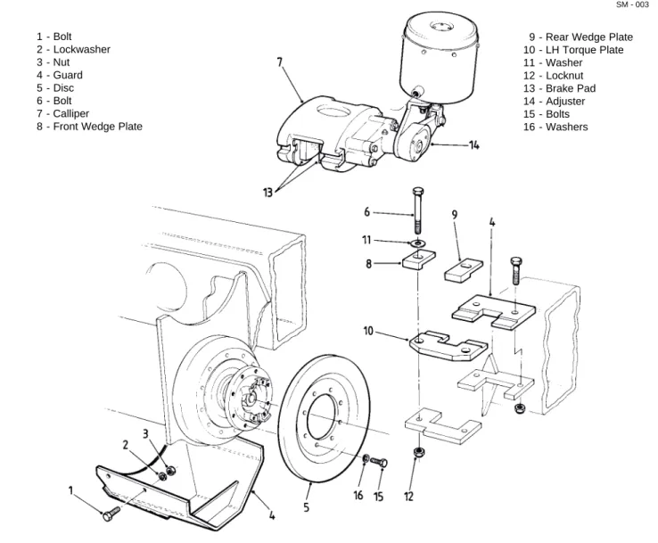
7. Slacken adjuster (14, Fig. 3) until brake pads (13, Fig. 3) are sufficiently clear of parking brake disc (5, Fig. 3) to permit removal of calliper (7, Fig. 3). 8. Note positions of front and rear wedge plates (8 & 9, Fig. 3) to aid in 'Installation'. Remove bolts (6, Fig. 3), washers (11, Fig. 3), nuts (12, Fig. 3), front and rear wedge plates (8 & 9, Fig. 3) and left hand torque plate (10, Fig. 3).
9. Move and secure calliper (7, Fig. 3) clear of parking brake disc (5, Fig. 3).
Note: Take extra care when handling drivelines since any deformity on a rotating mass creates vibration and excessive wear during any operation.
10. Match mark brake yoke (16) and mating surface of pivot - centre axle driveline (Fig. 2) to aid in
'Installation'. Remove bolts, lockwashers and caps and remove driveline from the machine.
11. Remove bolts (57) and lockwashers (14) from rear housing (31).
Note: Take extra care when handling driveshafts as any deformity on a rotating mass creates vibration and excessive wear during any operation.
Transmission - Pivot Pivot - Centre Axle
Section 100-0020
Chassis - Articulation and Oscillation Pivot
1 - Bolt 2 - Lockwasher 3 - Nut 4 - Guard 5 - Disc 6 - Bolt 7 - Calliper
8 - Front Wedge Plate
9 - Rear Wedge Plate 10 - LH Torque Plate 11 - Washer 12 - Locknut 13 - Brake Pad 14 - Adjuster 15 - Bolts 16 - Washers SM - 003
Fig. 3 - Parking Brake Assembly
12. Withdraw pivot driveshaft assembly from pivot by pulling rearwards on brake yoke/disc assembly and place in suitable location for further work.
13. Remove front locknut (25) then position front yoke (27) fully on to front of shaft (37) and suitably restrain to resist rotation. Remove rear locknut (25), washers (26) and rear yoke brake/disc assembly (16). Tag front and rear ends of shaft (37) and install locknuts (25) on the shaft to protect the threads.
14. Tag and remove housing (31). Note position of seal (40) to aid in 'Installation'. Remove and discard seal (40).
15. Remove washer (39), rear bearing (30) and spacer (19) from rear of shaft (37).
16. Remove bolt (56), lockwasher (57) and bracket
(58) securing pipe (3) to pivot (1) assembly. Note: Take care to avoid damaging pipe (3) when performing Steps 17 through 18.
17. Remove bolts (20) and lockwashers (14) from front housing (28).
18. Tag and remove front housing (28). Note position of seal (12) in front housing (28) to aid in 'Installation'. Remove and discard seal (12).
WARNING
When necessary to drive out components, use a soft drift to avoid injury and damage from flying chips.
4 SM 1975 4-00
Chassis - Articulation and Oscillation Pivot
Section 100-0020
20. Remove spacer (19). Note position of seals (29) in pivot (1) housing to aid in 'Installation'. Remove and discard seals (29).
Inspection
Numbers in parentheses refer to Fig. 1, unless otherwise specified.
1. Clean parts with a suitable solvent and let dry. DO NOT spin bearings with compressed air. Place bearings on clean surface, cover with lint free cloth and allow to dry.
2. Check pivot driveshaft bearings (30) for wear or damage, replace if required.
3. Inspect bushes (38) for wear. Replace if badly scored.
Installation
Numbers in parentheses refer to Fig. 1, unless otherwise specified.
Note: Tighten all fasteners without special torques specified, to standard torques listed in Section 300-0080, STANDARD BOLT AND NUT TORQUE SPECIFICATIONS.
Note: If bushes (38) are to be renewed, then proceed with Steps 1 thru 5, if the bushes (38) are satisfactory, proceed from Step 6.
WARNINGS
To prevent personal injury and property damage, make sure blocking or lifting
equipment is properly secured and of adequate capacity to do the job safely.
When necessary to drive out
components, use a soft drift to avoid injury and damage from flying chips.
1. Apply suitable heat to bushes (38) to break bond of retaining compound. Remove locknuts (25) from their protective position on shaft (37), then remove bushes (38) with a suitable drift.
2. Allow shaft (37) to cool. Thoroughly clean shaft (37) and new bushes (38) with a suitable solvent. Wash mating faces of shaft (37) and new bushes (38) with chlorethane and allow to dry.
3. Apply LOCTITE primer to mating faces of shaft (37)
SM - 004
Fig. 4 - Shaft and Bushes
1 - Shaft 2 - Bushes 3 - Shoulder
and new bushes (38) and allow to dry. Refer to Fig. 4. 4. Apply LOCTITE Fugeteile 35 to shaft (37) mating faces and install new bushes (38), with the recesses in bushes (38) against shoulder on driveshaft (37). Make sure that bushes (38) are fully home against the shoulders. Refer to Fig. 4.
5. Allow 15 minutes for retaining compound to cure to handling strength.
6. Degrease front bearing (30) housing in pivot (1) with a suitable solvent and allow to dry.
Note: Do not use retaining compound on the housing for the rear pivot shaft bearing.
Note: Front bearing (30) of shaft (37) is secured with retaining compound as well as normal hardware. Cleaning the bearing housing ensures a good bond. THE REAR BEARING IS SECURED BY NORMAL HARDWARE ONLY.
7. Apply coat of grease to new seals (29) and install seals in pivot housing. Make sure seal lips are facing outwards as shown on Fig. 5.
8. Make sure that pivot shaft bearing (30) is pre-packed with grease then position spacer (19), bearing (30) and washer (39) on rear of shaft (37). 9. Apply bead of grease to fill inner rim of new seal (40) and position new seal in rear housing (31). Refer to Fig. 6. Fill lube fitting (24) assembly on rear housing with grease and make sure that nipple (22) does not protrude into grease slot in rear face of housing (31).
Note: Take extra care when handling driveshafts as any deformity on a rotating mass creates vibration and excessive wear during any operation.
Section 100-0020
Chassis - Articulation and Oscillation Pivot
SM - 006
HOUSING SEAL
Fig. 6 - Typical Outer Seal Installation
SM - 005
SEAL
Fig. 5 - Pivot Housing Inner Seals
10. Assemble rear housing (31) and brake yoke/disc assembly (16) onto rear of shaft (37). Secure with locknut (25) and both washers (26) but only fingertight at this stage.
11. Insert shaft (37) assembly fully into pivot (1) from the rear. Take care not to dislodge internal seals (29). 12. Partially withdraw shaft (37) assembly to enable housing of rear pivot driveline bearing (30) to be filled with grease from 1/3 to 1/2 of capacity.
13. Reposition shaft (37) assembly fully in pivot (1). 14. Align housing (31) with lube fitting (24) uppermost and secure with lockwashers (14) and bolts (20). Torque tighten bolts (20) to 106 Nm (78 lbf ft).
15. Apply a bead of grease to fill inner rim of new seal (12) and position seal in front housing (28). Refer to Fig. 6. Fill pipe (3), through lube fitting (50), with grease. Make sure that pipe (3) does not protrude into grease slot in rear face of housing (28).
16. Install spacer (19) onto front of shaft (37).
17. Pre-pack bearing (30) with grease taking care not to place any grease on outer curved surface. Clean this surface with a suitable solvent where necessary and allow to dry.
Note: Make sure that Steps 18 through 22 are performed within the hardening time of the retaining compound in use.
18. Make sure mating surfaces of housing (28) are still clean then apply coating of retaining compound to mating surfaces of bearing (30) and housing (28). Install bearing (30) on to front of shaft (37).
19. Pack housing (28) of with grease from 1/3 to 1/2 of capacity.
20. Install front housing (28), front yoke (27), both washers (26) and locknut (25).
Note: Take care to avoid damaging the pipe (3) when performing Steps 21 through 22.
21. Lock brake yoke/disc (16) assembly with a suitable tool and install locknut (25) on front yoke (27). Torque tighten locknut (25) to 678 Nm (500 lbf ft).
22. Lock front yoke (27) and torque tighten locknut (25) on brake yoke assembly to 678 Nm (500 lbf ft). 23. Align front housing (28) with pipe (3) uppermost and secure in place with bolts (20) and lockwashers (14). Torque tighten bolts (20) to 106 Nm (78 lbf ft). 24. Install bracket (58), and secure with lockwasher (57) and bolt (56).
25. Check that no end float exists by pulling and pushing on the brake yoke/disc assembly.
Note: Take extra care when handling drivelines as chips, dents, burrs or deformity on any rotating mass creates vibration and excessive wear during any operation. (Steps 26 & 28).
6 SM 1975 4-00
Chassis - Articulation and Oscillation Pivot
Section 100-0020
has exhausted from the air tanks.
4. Position levelling jack under centre front portion of the front frame. Raise jack and block frame to remain level after removal of the articulation pins. Check that front wheels are still effectively blocked.
Note: Make sure that front frame is correctly supported and prevented from tilting on the axle, or damage to coupling etc. could result.
5. Disconnect steering cylinders by removing bolts (36), lockwashers (14), washers (45) and pins (44) from attachment points on pivot (1) housing. Move steering cylinders clear of pivot (1) housing and secure.
Note: Take extra care when handling drivelines as chips, dents, burrs or deformity on any rotating mass creates vibration and excessive wear during any operation.
6. Match mark yokes and mating surfaces of transmission - pivot driveline (Fig. 2) to aid in
'Installation'. Remove bolts, lockwashers and caps and remove driveline from the machine.
7. Remove bolt (53) and hardened washer (54)
securing pin (55) to pivot (1) housing. Remove nut (51) and withdraw pin (55), tapping pin downwards to ease removal. Take care not to damage the threads on pin (55).
Note: It may be necessary to adjust the frame levelling jack to relieve binding between pin (55) and pin bores during removal.
8. Remove bolt (46), lockwasher (14) and washer (47) securing pin (32) to pivot (1) housing.
9. Remove pin (32), tapping pin upwards to ease removal. Take care not to damage the threads on pin (32).
Note: It may be necessary to adjust the frame levelling jack to relieve binding between pin (32) and pin bores during removal.
10. Attach suitable lifting equipment to the rear frame and take up slack.
Note: Only separate the frames sufficiently to permit removal of the articulation bearings or damage to electrical, hydraulic and air connections could result. 11. Remove blocking from the rear frame and wheels 26. Connect pivot - centre axle driveline (Fig. 2) to
brake yoke/disc assembly as noted on 'Removal'. Install caps and secure with lockwashers and bolts. 27. Position parking brake calliper (7, Fig. 3) in position and install left hand torque plate (10, Fig. 3), front and rear wedge plates (8 & 9, Fig. 3) and secure in place with bolts (6, Fig. 3), washers (11, Fig. 3) and locknuts (12, Fig. 3).
28. Install transmission - pivot driveline (Fig. 2) with caps, lockwashers and bolts as noted on 'Removal'. 29. Position guard (4, Fig. 3), if fitted, and secure to frame using bolts (1, Fig. 3), lockwashers (2, Fig. 3) and nuts (3, Fig. 3).
30. Place the battery master switch in the on position, start the engine and allow air pressure in the tanks to build up to correct operating pressure.
31. Adjust parking brake as shown in Section 170-0010, PARKING BRAKE AND MOUNTING.
32. Remove all blocking from the road wheels.
ARTICULATION BEARINGS
Removal
Numbers in parentheses refer to Fig. 1, unless otherwise specified.
Note: The lengths of the electrical, hydraulic and air connections between the two frames are designed to permit articulation. As a result, the frames can be separated sufficiently to permit removal of the articulation bearings without disconnecting these connections.
WARNING
To prevent personal injury and property damage, make sure blocking or lifting
equipment is properly secured and of adequate capacity to do the job safely.
1. Position the vehicle in a level work area, apply the parking brake and switch off the engine.
2. Block all road wheels and place the battery master switch in the 'Off' position.
3. Open drain cocks on air tanks to drain air pressure from the tanks. Close air tank drain cocks when air
Section 100-0020
Chassis - Articulation and Oscillation Pivot
and use lifting equipment to pull the rear frame away from the front frame. After moving, block the rear frame and wheels securely.
12. Mark all bearing retainers (5, 11, 17 & 21) to aid in 'Installation'.
Note: Retainers (5, 11, 17 & 21) are not interchangeable.
13. Remove bolts (13), lockwashers (14), retainers (5, 11, 17 & 21) and upper and lower shims (7, 8 & 9). 14. Remove and discard 'O' rings (4, 10 & 18). Remove spacer (52) noting orientation to aid in 'Installation'.
15. Remove and tag all bearings (6) to aid in 'Installation', where appropriate.
Note: Never interchange cups or cones between bearings.
Inspection
Numbers in parentheses refer to Fig. 1.
1. Clean parts with a suitable solvent and let dry. DO NOT spin bearings with compressed air. Place bearings on clean surface, cover with lint free cloth and allow to dry.
2. Check articulation bearings (6) and pins (32 & 55) for wear or damage. Renew if required.
Installation
Numbers in parentheses refer to Fig. 1, unless otherwise specified.
WARNING
To prevent personal injury and property damage, make sure blocking or lifting
equipment is properly secured and of adequate capacity to do the job safely.
Note: Two bearings are installed on EACH articulation point. Each bearing comprises a cup and a cone and are installed into the articulation point with the cones 'back to back'. Refer to Fig. 7.
Note: Never interchange cups or cones between bearings.
1. Insert both bearing cups and cones into housing so
SM - 007
Fig. 8 - Measuring End Float
that bearing cones are back to back and position retainer (11), for top articulation bearing, and retainer (21), for bottom articulation bearing on underside of bearing housing. Make sure that bearings are pre-packed with grease including end faces and faces on bearing cups.
2. Install top retainer (5), for top articulation bearing, and retainer (21), for bottom articulation bearing. 3. Lubricate bolts (13 for top and 33 for bottom) and install along with washers (14). Torque tighten bolts (13 & 33) to 27 Nm (20 lbf ft).
4. Use feeler gauges to measure end float and record value. Refer to Fig. 8.
Note: End float is equal to the sum of the clearances between both retainers and the lug.
5. Select shims to total value of -0.07 to +0.02 mm (-0.003 to +0.001 in) of that recorded at Step 4.
1 - Upper Retainer 2 - Lower Retainer 3 - Upper 'O' Ring 4 - Lower 'O' Ring 5 - Shims 6 - Bolts 7 - Washers 8 - Cups 9 - Cones 10 - Lugs
Fig. 7 - Section Through Articulation Bearing
8 SM 1975 4-00
Chassis - Articulation and Oscillation Pivot
Section 100-0020
19. Place the battery master switch in the on position, start the engine and allow air pressure in the tanks to build up to correct operating pressure.
20. Lower and remove jack and all blocking equipment.
OSCILLATION BUSHES
Removal
Numbers in parentheses refer to Fig. 1, unless otherwise specified.
WARNING
To prevent personal injury and property damage, make sure blocking or lifting
equipment is properly secured and of adequate capacity to do the job safely.
1. Position the vehicle in a level work area, apply the parking brake and switch off the engine.
2. Block all road wheels and place the battery master switch in the 'Off' position.
3. Open drain cocks on air tanks to drain air pressure from the tanks. Close air tank drain cocks when air has exhausted from the air tanks.
4. Remove hydraulic oil tank remote drain plug and drain hydraulic oil into a suitable container. Re-install drain plug in hydraulic tank remote drain fitting. 5. Tag all air and hydraulic lines between front and rear frames to aid in 'Installation. Disconnect all air and hydraulic lines. Cap line fittings and plug lines to prevent ingress of dirt.
6. Disconnect electrical wiring and any other
attachments that would be damaged on separation of front and rear frames.
7. Position levelling jack under centre front portion of the front frame. Raise the jack and block the front frame, front and rear, so it will remain level after separation. Check that both front wheels are still securely blocked.
Note: Make sure that the front frame is correctly supported and prevented from tilting on the axle or damage to coupling etc. could result.
6. Remove bolts (13 & 33), lubricate and coat with anti-seize compound then install shims (7, 8 & 9) beneath appropriate upper retainer (5 for upper articulation bearing, 17 for lower articulation bearing). 7. Re-install bolts (13 & 33) and washers (14) and torque tighten to 106 Nm (78 lbf ft).
8. Install spacer (52) in upper bearing as noted on removal. Install upper 'O' ring (4) and lower 'O' ring (10) for top bearing (6).
Note: The lower bearing is NOT fitted with a spacer.
9. Install 'O' rings (18) for lower bearing (6).
10. Attach suitable lifting equipment to the rear frame and take up slack.
11. Remove blocking from rear frame and wheels. Move rear frame with lifting equipment to align the articulation pin bores. Block the rear frame and wheels to remain level and stationary.
12. Clean articulation pins (32 & 55) with suitable solvent, allow to dry then coat them with anti-seize compound including threads on upper pin (55). 13. Insert articulation pin (32).
Note: It may be necessary to adjust the levelling jack beneath front frame to permit entry of articulation pin (32). Pin (32) may be tapped in to place taking care that it is not misaligned and does not cause damage to the pin, bearings or pivot housing lugs.
14. Secure pin (32) with washer (47), lockwasher (14) and bolt (36).
15. Insert upper articulation pin (55).
16. Install nut (51) on pin (55). Torque tighten nut (51) to 1 424 Nm (1 050 lbf ft).
Note: Take extra care when handling drivelines as chips, dents, burrs or deformity on any rotating mass creates vibration and excessive wear during any operation.
17. Install transmission - centre driveline (Fig. 2) with caps, lockwashers and bolts as noted on 'Removal'. 18. Position steering cylinders in place on pivot (1) and install pins (44). Secure pins (44) with bolts (36), washers (45) and lockwashers (14).
Section 100-0020
Chassis - Articulation and Oscillation Pivot
assembly to avoid damage to end threads. 18. Replace thrust nut (34) on pivot (1) to protect threads.
19. Note position of front 'V' ring (41) to aid in 'Installation'. Remove and discard 'V' ring (41). 20. Inspect oscillation bushes (43) as described in 'Inspection'. If bushes are to be renewed, proceed with Step 20.
21. Remove oscillation bush/es (43) with hammer and chisel.
Note: The suggested method is to make an axial cut along the bush then to lever the bush in order to collapse it upon itself.
Inspection
Numbers in parentheses refer to Fig. 1.
1. Clean oscillation bushes (43) with a suitable solvent and allow to dry.
2. Inspect oscillation bushes (43) for wear, scoring, erosion and 'out of round'. Pay particular attention to the thrust faces of the bushes which should also be inspected for cracking/splitting. Renew if required.
Installation
Numbers in parentheses refer to Fig. 1, unless otherwise specified.
Note: Tighten all fasteners without special torques specified, to standard torques listed in
Section 300-0080, STANDARD BOLT AND NUT TORQUE SPECIFICATIONS.
WARNING
To prevent personal injury and property damage, make sure blocking or lifting
equipment is properly secured and of adequate capacity to do the job safely.
1. Wipe bush housing clean using suitable solvent and allow to dry.
2. Apply LOCQUIC primer to housing and allow to dry for 10 minutes. Apply LOCTITE RC-35 to housing. 3. Align new bushes to housing with grease holes aligned vertically and identification 'PAINT DOT' at Top Dead Note: Take extra care when handling drivelines as
chips, dents, burrs or deformity on any rotating mass creates vibration and excessive wear during any operation.
8. Remove bolts (1, Fig. 3), lockwashers (2, Fig. 3), nuts (3, Fig. 3) and protective guard (4, Fig. 3), if fitted, from beneath rear of pivot housing.
WARNING
Tensioned spring on adjuster.
9. Slacken adjuster (14, Fig. 3) until brake pads (13, Fig. 3) are sufficiently clear of parking brake disc (5, Fig. 3) to permit removal of calliper (7, Fig. 3). 10. Note positions of front and rear wedge plates (8 & 9, Fig. 3) to aid in 'Installation'. Remove bolts (6, Fig. 3), washers (11, Fig. 3), nuts (12, Fig. 3), front and rear wedge plates (8 & 9, Fig. 3) and left hand torque plate (10, Fig. 3).
11. Move and secure calliper (7, Fig. 3) clear of parking brake disc (5, Fig. 3).
Note: Take extra care when handling drivelines since any deformity on a rotating mass creates vibration and excessive wear during any operation.
12. Match mark brake yoke (16) and mating surface of pivot - centre axle driveline (Fig. 2) to aid in
'Installation'. Remove bolts, lockwashers and caps and remove driveline from the machine.
13. Mark disc (5, Fig. 3) assembly to aid in 'Installation' then remove bolts (15, Fig. 3) washers (16, Fig. 3) and disc (5, Fig. 3).
14. Remove bolts (36), lockwashers (14) and lockplate (35).
15. Using special tool, which can be fabricated as shown in Fig. 11, remove thrust nut (34) from pivot (1). Note position of rear 'V' ring (41) to aid in 'Installation'. Remove and discard 'V' ring (41).
16. Attach suitable lifting equipment to the front of the rear frame and take up slack.
17. Remove all blocking from rear frame and wheels and using suitable lifting equipment draw the rear frame from pivot (1) assembly. When clear, block the rear frame and wheels.
10 SM 1975 4-00
Chassis - Articulation and Oscillation Pivot
Section 100-0020
Centre. Refer to Fig. 9. Drift bushes into housing using hammer with soft packing for protection.
4. Using special tool, which can be fabricated as shown in Fig. 11, remove thrust nut (34) from pivot (1). Clean grease from pivot exterior using a suitable solvent where necessary and allow to dry. Note: Use care on inserting the pivot housing assembly or damage to the thread could occur. 5. Install new pre-greased front 'V' ring (41). Refer to Fig. 10. Apply liberal coat of grease to external surface of pivot (1) and mating faces of bushes (43).
6. Attach suitable lifting equipment to the front of the rear frame and take up slack.
7. Remove all blocking from rear frame and wheels and use lifting equipment to line-up and draw the rear frame onto pivot (1) assembly.
8. Install new pre-greased rear 'V' ring (41). Refer to Fig. 10. Using special tool, as shown in Fig. 11, install and tighten thrust nut (34) until there is no end float/ clearance at thrust face of either bush (43). Slacken thrust nut (34) until pin of lockplate (35) can be inserted in first available hole in thrust nut (34). 9. Secure lockplate (35) with bolts (36) and
Fig. 10 - Pivot Housing 'V' Ring Installation
lockwashers (14). Torque tighten bolts (36) to 75 Nm (55 lbf ft).
10. Grease oscillation bushes (43) through lube fittings (59) until excess lubrication is seen.
11. Check that no end float exists at oscillation bushes by pushing and pulling on brake yoke assembly.
12. Position brake disc (5, Fig. 3) onto brake yoke (16) as noted at 'Removal'. Secure in place with bolts (15, Fig. 3) and washers (16, Fig. 3).
Note: Take extra care when handling drivelines as
Fig. 9 - Installing Oscillation Bushes
SM - 011 PAINT DOT SM - 010 THRUST NUT PAINT DOT REAR 'V' RING FRONT 'V' RING LUBE HOLE LUBE HOLE OSCILLATION BUSH PAINT DOT
Section 100-0020
Chassis - Articulation and Oscillation Pivot
5. Remove bolts and lockwashers securing lockplate at the thrust nut and remove the lockplate.
6. Using special tool, which can be manufactured as shown in Fig. 11, tighten thrust nut until there is no end float/clearance at thrust face of either bush. Slacken thrust nut until pin of the lockplate can be inserted in the first available hole in the thrust nut.
7. Secure lockplate with bolts and lockwashers. Torque tighten bolts to 75 Nm (55 lbf ft).
8. Lower jack and remove all blocking from the front wheels.
MAINTENANCE
The end float/clearance at the thrust face of the oscillation bushes should be checked every 250 hours. Any clearance found must be removed by adjustment of the thrust nut, as described under 'Thrust Nut Adjustment'.
Note: A practical method of establishing the effective adjustment of the thrust nut is to use movement of the machines body in the raised position. Move the body from fully raised to almost fully raised while watching the effect of this action on the frame and pivot arrangement. Any slackness between the thrust nut and thrust faces will be clearly visible movement of the frame.
Very little other maintenance of the articulation and oscillation pivot is required other than to stress the importance of correct lubrication of the assembly. Lubricate the oscillation bushes, articulation bearings/ pins and the pivot driveshaft bearings in accordance with Section 300-0020, LUBRICATION SYSTEM but note the following
precautions:-Note: The oscillation bushes are lubricated every 10 to 15 hours.
Note: DO NOT exceed the lubrication schedule for the pivot driveshaft bearings i.e. 4 shots of a hand grease gun every 250 hours.
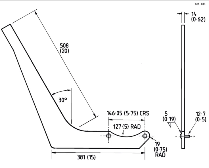
SPECIAL TOOL
The special tool required for removal and installation of the thrust nut, can be manufactured, as shown in Fig. 11.
chips, dents, burrs or deformity on any rotating mass creates vibration and excessive wear during any operation.
13. Connect pivot - centre axle driveline (Fig. 2) at brake yoke using bolts, lockwashers and caps as noted at 'Removal'.
14. Position parking brake calliper (7, Fig. 3) in position and install left hand torque plate (10, Fig. 3), front and rear wedge plates (8 & 9, Fig. 3) and secure in place with bolts (6, Fig. 3), washers (11, Fig. 3) and locknuts (12, Fig. 3).
15. Position guard (4, Fig. 3), if fitted, and secure to frame using bolts (1, Fig. 3), lockwashers (2, Fig. 3) and nuts (3, Fig. 3).
16. Remove all protective plugs and connect all air and hydraulic lines and other attachments disconnected in preparation for separation of front and rear frames. 17. Fill hydraulic oil tank with hydraulic oil, as specified in Section 300-0020, LUBRICATION SYSTEM. 18. Place the battery master switch in the on position, start the engine and allow air pressure in the tanks to build up to correct operating pressure. Check air and hydraulic lines for leaks. Tighten line fittings as required.
19. Adjust parking brake as shown in Section 170-0010, PARKING BRAKE AND MOUNTING. 20. Remove all blocking from the road wheels.
THRUST NUT ADJUSTMENT
1. Position the vehicle in a level work area, apply the parking brake and switch off the engine.
2. Block all road wheels and place the battery master switch in the 'Off' position.
3. Open drain cocks on air tanks to drain air pressure from the tanks. Close air tank drain cocks when air has exhausted from the air tanks.
4. Position levelling jack under centre front portion of the front frame and raise the jack to ensure both frames are parallel.
12 SM 1975 4-00
Chassis - Articulation and Oscillation Pivot
Section 100-0020
SM - 844
Fig. 11 - Fabrication Details of Thrust Nut Removal and Installation Tool
Dimensions in mm (in)
SPECIAL TORQUE SPECIFICATIONS
TORQUE
FIG. NO. ITEM NO. ITEM NAME Nm lbf ft
1 13 Bolt 106 78 1 20 Bolt 106 78 1 25 Nut 678 500 1 33 Bolt 106 78 1 36 Bolt 75 55 1 51 Nut 1 425 1 050
Section 100-0020
ARTICULATION AND OSCILLATION
PIVOT DIAGNOSIS
Noise and vibration caused by the pivot driveshaft assembly appear only at certain speeds and generally come and go as these speeds are approached and passed. When the driveshaft assembly noise becomes excessive, it takes the form of a vibration which can be
felt throughout the frame.
Noise from the articulation and oscillation points must be investigated.
An 'Articulation and Oscillation Pivot Diagnosis' table is shown below.
Chassis - Articulation and Oscillation Pivot
* * * *
ARTICULATION AND OSCILLATION PIVOT DIAGNOSIS
CONDITION REASON REMEDY
Noise (Pivot Driveshaft) Insufficient lubricant Check seals.
Install proper grade of lubricant. Out of balance driveshaft assembly Check alignment.
Vibration (Pivot Driveshaft) Backlash due to worn bearings, Renew worn parts.
housings, yokes and trunnions
Yoke not in line Renew driveshaft assembly or
assemble correctly.
Driveshaft out of balance Renew driveshaft assembly.
Noise (Articulation/Oscillation Excessive run out or distorted yokes Dismantle and correct, or renew,
Points) damaged part.
Loose nut on yoke Check splines, if worn. Renew shaft.
Torque tighten nut to value in 'Special Torque Specifications' in this section.
Insufficient lubricant Lubricate. Investigate/revise lubrication
schedules. Refer to Section 300-0020, LUBRICATION SYSTEM. Check seals for lubricant loss/contamination. Renew as necessary.
Section 100-0020
DESCRIPTION AND OPERATION
The articulation and oscillation pivot allows the front and rear frames to rotate horizontally (articulation) and tilt laterally (oscillation) with respect to each other. It is also the main load bearing coupling between the two frames. The pivot assembly houses the driveshaft connecting the drive between the front and rear frames.
Articulation bearings, oscillation bushes, pivot driveshaft bearings and associated parts can be removed, inspected and replaced or renewed by following the procedures outlined in this section.
Fig. 1 - Articulation and Oscillation Pivot
CHASSIS - Articulation and Oscillation Pivot
SM - 2495
* Lower bearing shims not shown
33 - Bolt 34 - Thrust Nut 35 - Lockplate 36 - Bolt 37 - Shaft 38 - Bush 39 - Washer 40 - Seal 41 - 'V' Ring 42 - Adaptor 43 - Bush 44 - Pin 45 - Washer 46 - Bolt 47 - Washer 48 - Lube Line 49 - Connector 50 - Lube Fitting 51 - Nut 52 - Spacer 53 - Bolt 54 - Hardened Washer 55 - Pin 56 - Bolt 57 - Lockwasher 58 - Bracket 59 - Lube Fitting 60 - Guard 61 - Bolt 62 - Lockwasher 1 - Pivot 2 - Coupling 3 - Pipe 4 - 'O' Ring 5 - Retainer 6 - Bearing *7 - Shim *8 - Shim *9 - Shim 10 - 'O' Ring 11 - Retainer 12 - Seal 13 - Bolt 14 - Lockwasher 15 - Lube Fitting 16 - Brake Yoke 17 - Retainer 18 - 'O' Ring 19 - Spacer 20 - Bolt 21 - Retainer 22 - Nipple 23 - Elbow 24 - Lube Fitting 25 - Locknut 26 - Washer 27 - Front Yoke 28 - Housing 29 - Seal 30 - Bearing 31 - Housing 32 - Pin 44 45 14 36 13 14 6 7,8,9 51 52 4 5 1 61 62 60 41 43 41 34 35 36 14 25 26 20 14 16 23 22 24 2 22 31 40 39 30 19 29 38 37 38 59 42 48 48 49 49 LUBRICATION POINT 32 18 15 6 18 21 20 28 30 19 29 17 12 2,3,50 14 27 26 25 56 57 58 53 54 55 11 10 33 14 46 14 47
2 SM 1988 Rev 1 11-00
Chassis - Articulation and Oscillation Pivot
Section 100-0020
PIVOT DRIVESHAFT BEARINGS
Removal
Numbers in parentheses refer to Fig. 1, unless otherwise specified.
Note: It is not necessary to separate the frames in order to remove the pivot driveshaft assembly.
WARNING
To prevent personal injury and property damage, make sure blocking or lifting
equipment is properly secured and of adequate capacity to do the job safely.
1. Position the vehicle in a level work area, apply the parking brake and switch off the engine.
2. Block all road wheels and place the battery master switch in the 'Off' position.
3. Open drain cocks on air tanks to drain air pressure from the tanks. Close air tank drain cocks when air has exhausted from the air tanks.
Note: Take extra care when handling drivelines as any deformity on a rotating mass creates vibration and excessive wear during any operation.
4. Match mark yokes and mating surfaces of transmission - pivot driveline (Fig. 2) to aid in
'Installation'. Remove bolts, lockwashers and caps and remove driveline from the machine.
Note: Take care to avoid damaging pipe (3) when performing Step 5.
5. Remove locknut (25) and washers (26) from front
Fig. 2 - Drivelines
yoke (27). Remove yoke (27) from shaft (37). 6. Remove bolts (1, Fig. 3), lockwashers (2, Fig. 3), nuts (3, Fig. 3) and protective guard (4, Fig. 3), if fitted, from beneath rear of pivot housing.
WARNING
Tensioned spring on adjuster.
7. Slacken adjuster (14, Fig. 3) until brake pads (13, Fig. 3) are sufficiently clear of parking brake disc (5, Fig. 3) to permit removal of calliper (7, Fig. 3). 8. Note positions of front and rear wedge plates (8 & 9, Fig. 3) to aid in 'Installation'. Remove bolts (6, Fig. 3), washers (11, Fig. 3), nuts (12, Fig. 3), front and rear wedge plates (8 & 9, Fig. 3) and left hand torque plate (10, Fig. 3).
9. Move and secure calliper (7, Fig. 3) clear of parking brake disc (5, Fig. 3).
Note: Take extra care when handling drivelines since any deformity on a rotating mass creates vibration and excessive wear during any operation.
10. Match mark brake yoke (16) and mating surface of pivot - centre axle driveline (Fig. 2) to aid in
'Installation'. Remove bolts, lockwashers and caps and remove driveline from the machine.
11. Remove bolts (57) and lockwashers (14) from rear housing (31).
Note: Take extra care when handling driveshafts as any deformity on a rotating mass creates vibration and excessive wear during any operation.
Transmission - Pivot Pivot - Centre Axle
Section 100-0020
Chassis - Articulation and Oscillation Pivot
1 - Bolt 2 - Lockwasher 3 - Nut 4 - Guard 5 - Disc 6 - Bolt 7 - Calliper
8 - Front Wedge Plate
9 - Rear Wedge Plate 10 - LH Torque Plate 11 - Washer 12 - Locknut 13 - Brake Pad 14 - Adjuster 15 - Bolts 16 - Washers SM - 003
Fig. 3 - Parking Brake Assembly
12. Withdraw pivot driveshaft assembly from pivot by pulling rearwards on brake yoke/disc assembly and place in suitable location for further work.
13. Remove front locknut (25) then position front yoke (27) fully on to front of shaft (37) and suitably restrain to resist rotation. Remove rear locknut (25), washers (26) and rear yoke brake/disc assembly (16). Tag front and rear ends of shaft (37) and install locknuts (25) on the shaft to protect the threads.
14. Tag and remove housing (31). Note position of seal (40) to aid in 'Installation'. Remove and discard seal (40).
15. Remove washer (39), rear bearing (30) and spacer (19) from rear of shaft (37).
16. Remove bolt (56), lockwasher (57) and bracket
(58) securing pipe (3) to pivot (1) assembly. Note: Take care to avoid damaging pipe (3) when performing Steps 17 through 18.
17. Remove bolts (20) and lockwashers (14) from front housing (28).
18. Tag and remove front housing (28). Note position of seal (12) in front housing (28) to aid in 'Installation'. Remove and discard seal (12).
WARNING
When necessary to drive out components, use a soft drift to avoid injury and damage from flying chips.
4 SM 1988 Rev 1 11-00
Chassis - Articulation and Oscillation Pivot
Section 100-0020
20. Remove spacer (19). Note position of seals (29) in pivot (1) housing to aid in 'Installation'. Remove and discard seals (29).
Inspection
Numbers in parentheses refer to Fig. 1, unless otherwise specified.
1. Clean parts with a suitable solvent and let dry. DO NOT spin bearings with compressed air. Place bearings on clean surface, cover with lint free cloth and allow to dry.
2. Check pivot driveshaft bearings (30) for wear or damage, replace if required.
3. Inspect bushes (38) for wear. Replace if badly scored.
Installation
Numbers in parentheses refer to Fig. 1, unless otherwise specified.
Note: Tighten all fasteners without special torques specified, to standard torques listed in Section 300-0080, STANDARD BOLT AND NUT TORQUE SPECIFICATIONS.
Note: If bushes (38) are to be renewed, then proceed with Steps 1 thru 5, if the bushes (38) are satisfactory, proceed from Step 6.
WARNINGS
To prevent personal injury and property damage, make sure blocking or lifting
equipment is properly secured and of adequate capacity to do the job safely.
When necessary to drive out
components, use a soft drift to avoid injury and damage from flying chips.
1. Apply suitable heat to bushes (38) to break bond of retaining compound. Remove locknuts (25) from their protective position on shaft (37), then remove bushes (38) with a suitable drift.
2. Allow shaft (37) to cool. Thoroughly clean shaft (37) and new bushes (38) with a suitable solvent. Wash mating faces of shaft (37) and new bushes (38) with chlorethane and allow to dry.
3. Apply LOCTITE primer to mating faces of shaft (37)
SM - 004
Fig. 4 - Shaft and Bushes
1 - Shaft 2 - Bushes 3 - Shoulder
and new bushes (38) and allow to dry. Refer to Fig. 4. 4. Apply LOCTITE 638 to shaft (37) mating faces and install new bushes (38), with the recesses in bushes (38) against shoulder on driveshaft (37). Make sure that bushes (38) are fully home against the shoulders. Refer to Fig. 4.
5. Allow 15 minutes for retaining compound to cure to handling strength.
6. Degrease front bearing (30) housing in pivot (1) with a suitable solvent and allow to dry.
Note: Do not use retaining compound on the housing for the rear pivot shaft bearing.
Note: Front bearing (30) of shaft (37) is secured with retaining compound as well as normal hardware. Cleaning the bearing housing ensures a good bond. THE REAR BEARING IS SECURED BY NORMAL HARDWARE ONLY.
7. Apply coat of grease to new seals (29) and install seals in pivot housing. Make sure seal lips are facing outwards as shown on Fig. 5.
8. Make sure that pivot shaft bearing (30) is pre-packed with grease then position spacer (19), bearing (30) and washer (39) on rear of shaft (37). 9. Apply bead of grease to fill inner rim of new seal (40) and position new seal in rear housing (31). Refer to Fig. 6. Fill lube fitting (24) assembly on rear housing with grease and make sure that nipple (22) does not protrude into grease slot in rear face of housing (31).
Note: Take extra care when handling driveshafts as any deformity on a rotating mass creates vibration and excessive wear during any operation.