ISSN 1411-1284
Abstract— This paper reports on the investigation of optimum cutting condition in term of tool life and surface roughness when end milling titanium alloy (Ti-6Al-4V) using uncoated solid carbide under flood conditions. Factorial design of experiment coupled with response surface methodology (RSM) were used in developing the predicted mathematical models in relation to the primary machining variables such as cutting speed, feed and radial rake angle. Overlay plot was also constructed and used in determining the optimum cutting conditions for a particular range of cutting conditions. Experimental results showed that the primary machining variables have a significant effect to the optimum cutting condition when end milling Ti-6Al4V.
Keywords—End Milling, Response Surface Methodology, Surface Roughness, Tool Life, Titanium Alloy.
I. INTRODUCTION
Increasing trend in using titanium alloy for airframe structures is mainly due to its high resistance to oxidation at elevated temperature and its low weight-to-strength ratio. However, due to poor machinability of titanium alloys that are found in the machining of titanium-based alloys are mostly due to the high levels of hardness at high temperature that these materials have, in particular when compared to steels with similar properties. The appropriate selection of tool materials, cutting parameters and coolant lubrication constitutes the basis for safe machining process. Therefore selecting the machining conditions and parameters is crucial. Previous study have shown that the appropriate range of feeds and cutting speeds, which provide a satisfactory tool life, surface roughness and cutting force, is very limited. [1][2][3][4]
Although in the past, many studies had been carried out to predict the tool life [5]-[9] and surface roughness [10]-[15] during end milling operation in terms of the primary machining parameters, only few of them took the effect of tool geometry into consideration [5][10][12][12]. Therefore, an effort has been made in this investigation to evaluate the influence of tool geometry (radial rake angle), cutting speed and feed rate when end milling Ti-6Al4V using solid carbide tool.
The aim of this research was to find the optimum cutting condition by mean the predicted mathematical models (first and second order) for tool life, surface roughness and cutting forces when end milling titanium alloy (Ti-6Al-4V) using uncoated solid carbide under
flood conditions. Response surface methodology (RSM) was adopted which is one of most useful tools for modeling and analysis of problems in which a response of interest is influenced by several variables and the objective is to optimize this response [16][17] using package software design expert 6.0 [18].
Investigation of Optimum Cutting Condition
when End Milling Titanium Alloy Ti-6Al-4V
A.S. Mohruni
1, S. Sharif
2, M.Y. Noordin
2, V.C. Venkatesh
3.
1
Department of Mechanical Engineering, Sriwijaya University, Indralaya, South Sumatra, Indonesia.
2
Department of Manufacturing and Industrial Engineering, Universiti Teknologi Malaysia, Johore, Malaysia.
3
Faculty of Engineering and Technology, Multimedia University, Malacca, Malaysia.
II. METHODOLOGY
A. Experimentation
For conducting the experimentation a CNC MAHO 700S milling machine was used. The side milling operation was investigated, which was carried out with a constant aa (axial depth of cut) 5 mm and ap (radial depth
of cut) 2 mm under flood conditions using 6% of concentration water base coolant. A new solid carbide end mill grade K30 with different radial rake angle, cutting speed and feed rate according to the experimental design was used for each machining trials.
A Taylor Hobson surface tester Surtronic +3 for collecting data of surface finish and a Nikon toolmaker microscope for observing the wear progression of cutting tools.
Two pieces of Ti-6Al-4V blocks were used for the side milling operation. One rectangular block was clamped on the dynamometer for recording the cutting force. Another one was clamped on the machine table for observing the wear progression of the cutting tools Fig. 1.
Fig. 1 The proposed CCD design used in observation
B. Experimental Design
The design of experimentation has a major effect on the number of conducted experiments. In this study, the two level factorials design was used to determine the significant factors as screening trials. Furthermore the
ISSN 1411-1284
factorial points are not replicated. The it is useful to add center points in screening to construct an estimate error with nc -1 and to observe the effect of non linearity in the
region of exploration.
C. Coding of the Independent Variables
The variables were coded by taking into account the capacity and limiting cutting conditions of the milling machine. Using the following transformations
1
3
2
4 8 7
6 5
9 11 12
10 13
14
15
17
19
21 22 23 24
20
18
16
x1 x2 x3
0 n 1 n
0 n n
x
ln
-x
ln
x
ln
-x
ln
x
=
(1)where x is the coded value of any factor corresponding to its natural value xn, xn1 is the +1 level and xn0 is the natural
value of the factor corresponding to the base of zero level [5][7][8][9][10][11][12][13][14][15]. The level and coding of the independent variables are presented in TABLE 1, while the cutting conditions in TABLE 2.
TABLE 1
LEVELS OF INDEPENDENT VARIABLES FOR TI-6AL-4V Levels Lowest Low Center High Highest
Coding -1.4142 -1 0 1 1.4142
Cutting Speed, V (m/min)
124.53 130 144.22 160 167.03
Feed, fz
(mm/tooth) 0.025 0.03 0.046 0.07 0.083 Radial Rake
Angle, (RRA), γ
6.16 7 9.54 13 14.78
Fig. 2 The proposed CCD design used in observation
For further observation for obtaining more information in extended observation region the central composite design CCD will used as the design of experiments Fig. 2.
The distance between center points and star points α = 1.4142, which calculated according the previous study [5] for nc = 4 with 3 factors.
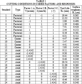
TABLE 2
CUTTING CONDITIONS IN CODED FACTORS AND RESPONSES
Standard Type Factor 1 A, V(m/min)
Factor 2 B, fz(mm/th)
Factor 3 C,
γ (o)
Tool Life TL (min)
Surface roughness,
Ra (µm)
1 Factorial -1 -1 -1 19.44 0.365
2 Factorial 1 -1 -1 12.32 0.256
3 Factorial -1 1 -1 2.80 0.498
4 Factorial 1 1 -1 1.29 0.464
5 Factorial -1 -1 1 7.41 0.428
6 Factorial 1 -1 1 2.44 0.252
7 Factorial -1 1 1 0.56 0.561
8 Factorial 1 1 1 0.31 0.512
9 Center 0 0 0 4.47 0.464
10 Center 0 0 0 5.47 0.444
11 Center 0 0 0 4.41 0.448
12 Center 0 0 0 5.93 0.424
13 Axial -1.4142 0 0 9.11 0.328
14 Axial -1.4142 0 0 9.30 0.324
15 Axial 1.4142 0 0 0.41 0.236
16 Axial 1.4142 0 0 0.48 0.240
17 Axial 0 -1.4142 0 20.54 0.252
18 Axial 0 -1.4142 0 21.08 0.262
19 Axial 0 1.4142 0 0.33 0.584
20 Axial 0 1.4142 0 0.35 0.656
21 Axial 0 0 -1.4142 6.62 0.304
22 Axial 0 0 -1.4142 6.94 0.288
23 Axial 0 0 1.4142 6.46 0.316
24 Axial 0 0 1.4142 6.24 0.348
ISSN 1411-1284
III. RESULTS AND DISCUSSION
Using Software package Design Expert 2.0 the results will be presented in figure form so that it is easier to understand the characteristic of the prediction models generated for the experiment trials.
A. Prediction models and Contours for the Tool Life
From the analysis with Ln transformation, the developed 3F1 tool life predictions model in coded factor is
ŷ = 0.9883-0.3667x1–1.10502x2–0.70237x3 (2)
Equation (2) can be transformed by using equation (1) to provide the predictive tool life (min) as
Ť = 12319906.47 V-3.5321 fz -2.6083γ -2.2692 (3)
where Ť is the predicted tool life (min)
Fig. 3 The contour of 3F1-predictions model.
This equation is valid for side milling of titanium alloy Ti-6Al-4V using solid carbide under flood conditions with the following ranges of cutting speed V, feed per tooth fz and radial rake angle γ: 130≤ V ≤160
m/min; 0.03≤ fz≤0.07 mm/tooth; 7≤γ≤ 13 (o).
The contour of 3F1-model in Fig. 3 shown, that the tool life decreased with increasing of the cutting speed. This result is supported by Taylor’s equation for tool life.
B. Prediction models and Contours for the Surface Roughness
Using the Ln transformations, the second order CCD-prediction model in coded factor is
2
The contour of the surface roughness predictions model is shown in Fig. 4.
This equations is valid for the range of observation; cutting speed V, feed per tooth fz and radial rake angle
γ, which are; 124.53≤ V ≤167.03 m/min; 0.025≤ fz
≤0.083 mm/tooth; 6.16≤γ≤ 14.78 (o) respectively.
Fig. 4 The contour of the second order CCD- surface roughness predictions model.
From the contour of surface roughness shown in Fig. 4, it is to recognize that the surface roughness reduced with increasing the cutting speed until certain values. Further increase of cutting speed affected on higher surface roughness value. This phenomenon could be explained through the influence of vibration, which may contribute to the instability of cutting tool when the machining process occurred.
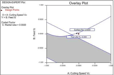
C. Overlay Plot for the Tool Life and Surface Roughness Model
To investigate the optimum cutting condition when end milling of titanium alloy Ti-6Al-4V, it is useful to construct overlay plot for the whole responses considered in observation.
The first overlay plot is for the range of observation region with α = -1 to +1, which presented in Fig. 5. The grey region is the optimum cutting condition, which has the following boundary; 4 min≤ tool life ≤ 19.44 min, 0.252 µm≤ Ra ≤ 0.4 µm.
Fig. 5 The overlay plot of the responses with observed region -1 level to +1 level
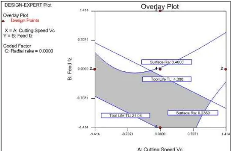
ISSN 1411-1284
The second overlay plot (Fig. 6) is for the range of observation region with α = -1.4142 to + 1.4142. This gives more view in extended region. With this view, it can also give more information gathered for extreme boundary conditions. The grey region is the optimum cutting conditions in extended observation range, which has the following boundary; 4 min≤ tool life ≤ 21.08 min, 0.236 µm≤ Ra ≤ 0.4 µm.
Fig. 6 The proposed CCD design used in observation
IV. CONCLUSIONS
1. Cutting speed, feed rate and radial rake angle are the primary factors influencing the tool life, surface roughness and cutting force.
2. The tool life decrease linearly with increasing cutting speed.
3. Surface roughness reduced with increasing the cutting speed until certain values. Further increase of cutting speed affected on higher surface roughness value.
4. Based on the overlay plots, it was found that the grey regions are the optimum cutting conditions for both observation ranges respectively.
ACKNOWLEDGMENT
The authors wish to thank the research Management Center, UTM and the Ministry of Science, Technology and Innovation Malaysia for their financial support to the above project through the IRPA funding 03-02-06-0086 EA001 – Vote no. 74122
REFERENCES
[1]. M. Dumitrescu, M.A. Elbestawi, T.I. El-Wardhany, “Mist coolant applications in high speed machining of advanced materials”, in. Metal Cutting and High speed Machining, Edited by D. Dudzinksi, A. Molinari, H. Schulz, Kluwer, 2002, pp. 329-339.
[2]. L.N. Lopez del acalle, J. Perez, J.I. Llorente, J.A. Sanchez, “Advanced cutting conditions for the milling of aeronautical alloys”, Journal of Materials Processing Technology Vol 100, no. 1-3, pp. 1-11, 2000.
[3]. E. Brinksmeier, U Berger, R. Jannsen, “High speed milling of Ti-6Al-4V for aircraft application”, in Proc. First French and German Conference on High Speed Machining 1997, Metz, pp. 295-306.
[4]. Niemann, H.; Eu-gene Ng.; Loftus, H.; Sharman, A.; Dewes, R. and Aspinwall, D., “The Effect of Cutting Environment and Tool Coating when High Speed Ball Nose End Milling titanium Alloy”, in Metal Cutting and High Speed Machining, edited by Dudzinski, D.; Molinari, A.; Schulz, H., Kluwer Academic/Plenum Publisher, 2002, pp.181-189.
[5]. S. Sharif, A.S. Mohruni, M.Y. Noordin, “Modeling of tool life when end milling on Titanium Alloy (Ti-6Al-4V) using response surface methodology”, in Proc. 1st International Conference & 7th AUN/SEED-Net Field wise Seminar on Manufacturing and Material Processing 2006, Kuala Lumpur, Malaysia, pp. 127-132.
[6]. Tool life testing in milling, Part 2: End Milling, ISO 8688, 1989 (E) 1-26.
[7]. M. Alauddin, M.A. El Baradie, M.S.J. Hashmi, “Prediction of tool life in end milling by response surface methodology”, Journal of Materials Processing Technology Vol. 71, no.3, pp. 456-465, 1997.
[8]. S.M. Wu, “Tool life testing by response surface methodology, part I and part II”, trans. ASME 86, pp. 105-116, 1964.
[9]. I.A. Choudhury, M.A. El Baradie, “Tool life prediction model by design of experiments for turning high strength steel (290 BHN)”, Journal of Materials Processing Technology Vol. 77, no.1-3, pp. 319-326, 1998.
[10]. S. Sharif, A.S. Mohruni, M.Y. Noordin, V.C. Venkatesh, “Optimization of surface roughness prediction model in end milling titanium alloy (Ti-6Al-4V)”, In Proceeding International Conference on Manufacturing Science and Technology ICOMAST 2006, 28-30 August 2006, Malacca, Malaysia, accepted for publication.
[11]. N.S.K. Reddy, P.V. Rao, “A Genetic Algorithmic approach for optimization of surface roughness prediction model in dry milling”, Machining Science and Technology Vol. 9 no. 1, pp. 63-84, 2005.
[12]. N.S.K. Reddy, P.V. Rao, “Selection of optimum tool geometry and cutting conditions using a surface roughness prediction model for end milling”, The International Journal of Advanced Manufacturing Technology, Vol. 26 no. 11-12, pp. 1202-1210, 2005.
[13]. Y. Sahin, A.R. Motorcu, “Surface roughness model for machining mild steel with coated carbide tool”, Material & Design Vol. 26 no. 4, pp. 321-326, 2005.
[14]. A. Mansour, H. Abdalla, “Surface roughness model for end milling: a semi-free cutting carbon casehardening steel (EN32) in dry condition”, Journal of Materials Processing Technology, Vol. 124 no.1-2, pp. 183-191, 2002.
[15]. M. Alauddin, M.A. El Baradie, M.S.J. Hasmi, “Optimization of surface finish in end milling Inconel 718”, Journal of Materials Processing Technology, Vol. 56 no. 1, pp. 54-65, 1996.
[16]. R.H. Myers, D.C. Montgomery, Response surface Methodology: Process and Product Optimization using Designed Experiments 2nd Edition, Wiley, 2002.
[17]. D.C. Montgomery, Design and Analysis of Experiments, 5th
ed. Wiley, New York, 2001.
[18]. Design Expert Software, Version 6, User’s Guide, Technical Manual, Stat-Ease Inc., Minneapolis, MN, 2000