1
MONITORING SYSTEMS DESIGN FOR EARLY DAMAGE DETECTION
OF ELECTRIC MOTOR BASED COMPUTER
Tugino1, Harianto 2, Widian Cahyo 1 1
Department of Electrical Engineering College of National Technology (STTNAS)
2
Department of MechanicalEngineering College of National Technology (STTNAS)
Jl. Babarsari CT Depok Sleman Yogyakarta 55281 Telp: 0274 485390, Fax 024 487249
Abstract
Damage to the electric motor can be detected at an early stage of temperature and vibration. temperature and electric motor abnormal vibration occurs due to the damage including damage to the bearing, load imbalance, misalignment, insulation failure in the motor windings and others.
This research aims to design of monitoring system for temperature and vibration analysis of electric motors based computer. This research can be used to help detect early occurrence of early damage to the electric motor that can lead to patterns of temperature and vibration and amplitude are likely to rise, so it can endorse the program of maintenance on the electric motor. The design consists of temperature and vibration sensors, sensor amplifier, data acquisition and computer programmed with Labview.
After testing it was found that the tool has been able to work as expected. Testing patterns of temperature and vibration motor disorders tended to be higher than the motor works normally. temperature and vibration motors higher the bias caused by the motor load is not balanced, there is damage to the winding or mechanical damage. In testing shows that the temperature and vibration monitoring will be detected if there are irregularities in the motor which will cause a rise in temperature and vibration. If the rise exceeded the limit that has been setup then the tool will turn on alarm lights
Keywords : early detection, damage, electric motor, monitoring system , computer
.
1. INTRODUCTION
The electric motor is indispensable for industry and households, covering a lot of use of such use for propulsion, conveyors, pumps, compressors and others. Most users will hardly notice the motor on the causes of damage to the motor. Sometimes users do not know the causes of damage of the motor. Actual damage to the motor can be detected at an early stage of its temperature
and vibration. Electric motor abnormal
temperature and vibration that occurs due to the damage of which damage to the bearing, load imbalance, misalignment, insulation failure in the motor windings and others. Examples damage in Industrial Motor shown in Fig 1. Temperature rating of the insulation class Motor shown in Table 1. An electrician can detect the type and extent of damage to the electric motor temperature signal like a doctor detect disease patients by analyzing pulse/heart rate.
Fig 1. Examples damage Motor in the Industry
Table 1. Temperature rating of the insulation class Motor
Temperature rating of class isolation Insulation
class
The maximum winding temperature
(C) A
B* F* H
105° 130° 155° 180°
697
Early detection of damage to the motor by looking at the pattern of the motor temperature that occurs can support predictive maintenance program that is currently promoted by the industry.
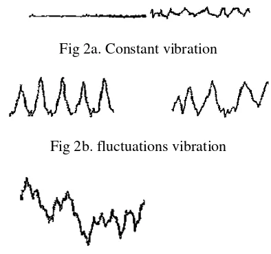
Vibration categorized into sections such that a constant vibration when the indicated value of the measuring device is not changed or fluctuated only slightly as shown in Fig 2a.
Fig 2a. Constant vibration
Fig 2b. fluctuations vibration
Fig 2c. Fluctuations irregular vibration
Fig 2. Basic forms of fluctuation in vibration level over time
If the value indicated on the measuring device fluctuates periodically or only intermittently, then the average of the maximum values indicated in each fluctuation was taken called vibration fluctuations (Fig 2b). Fluctuations irregular vibration which is if the indicated value of the measuring device fluctuates irregularly recorded as much as the same amount of time at the same interval as in Fig 2c.
2.RESEARCH PURPOSES
This research aimed to determine and study the effect of temperature and vibration as a result of damage to the motor. The temperature and vibration were in response to an electrical or mechanical system either caused by a given excitation force and change in operating conditions as a function of time. Comparative analysis of the motor temperature in good condition (normal) and the defects in components made in stages such that it can be determined the type and extent of damage the motor. This study is also intended to acquire a new alternative monitoring systems engineering and analysis of
temperature and vibration of electric motor that uses a computer base with good performance but at a cheaper cost and materials available in the Indonesian market. In addition, to reduce the dependence factor of temperature and vibration monitoring devices that tend to come from imports are expensive and hard to come by. In addition to mastery of computer application technology on temperature monitoring systems as well as to develop local human resources creative and productive. From the results of future research is the product of technology that can be developed and marketed with the cooperation of electronics and computer companies in the country.
3.RESEARCH METHODS
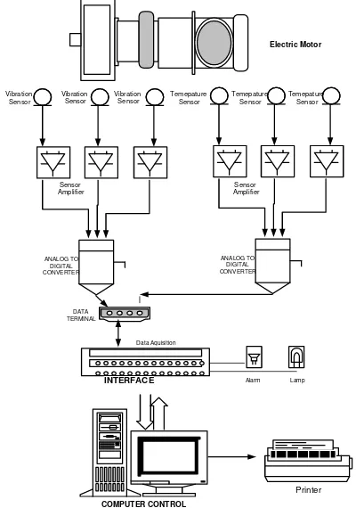
The study begins with collecting data monitoring and analysis system temperature electric motor. The data collected is used to design the system (hardware) and software of the temperature monitoring tool. Execution design and manufacture is done step by step in order to obtain maximum results. Methods of system design tool begins by creating a separate temperature monitoring devices of the computer system, having obtained maximum results are then combined into a system that will be used. The use of computers as a tool used to facilitate display the results of the motor temperature, the analysis of the results and working system. Equipment monitoring and analysis system temperature and vibration electric motors planned to consist of several series including the temperature sensor, vibration sensor, sensor amplifier, data acquisition, computer with Labview program, ADC (Analog to Digital Converter), Alarm and indicator lights. Fig 3 shows a block diagram of monitoring tools and
analysis Computer-based electric motor
temperature and vibration. Monitoring system include program plan that will be used in the monitoring system and electric motor temperature analysis is based computer. The programs include system selection on the menu display, reading of 3 units of motor temperature sensor consists of a temperature sensor A, B and C and 3 units vibration sensor. The temperature and Vibration readings from the sensors can be displayed in real time and used for data analysis.
698
a data base that will be used for purposes of data analysis for daily, weekly or monthly.
COMPUTER CONTROL INTERFACE
ANALOG TO DIGITAL CONVERTER
DATA TERMINAL
Electric Motor
Lamp Alarm
Vibration Sensor
Printer
ANALOG TO DIGITAL CONVERTER
Data Aquisition
Vibration Sensor
Vibration Sensor
Temepature Sensor
Temepature Sensor
Temepature Sensor
Sensor Amplifier
Sensor Amplifier
Fig.3. Block diagram of temperature and vibration monitoring and analysis of electric motor based
Computer
4. RESEARCH RESULT
After performing the manufacture of tool monitoring system, then the next to test each piece and having achieved a good result overall testing continued. Testing includes testing of temperature sensors, vibration sensors, sensor amplifier circuit, and temperature monitoring systems interfacing with the computer.
.
Fig 4. Hardware on early detection of damage the electric motor based computer
Testing the temperature sensor and the amplifier is intended to determine the characteristics of the
sensor. Testing is done by connecting the sensor to the sensor input to the output amplifier incorporated into data acquisition and then read on a computer. Hardware, Display and Labview Program on early detection of damage the electric motor based computer shown on Fig 4. Fig 5. and Fig 6.
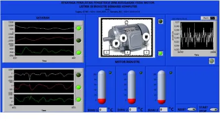
Fig 5. Display program on early detection of damage the electric motor based computer
Fig 6. Labview program on early detection of damage the electric motor based computer
699
Temperature SensorTemperature Sensor
Temperature Sensor
Fig 7. Laying the temperature sensor on the electric motor
Fig 8. Results of an experiment of LM35 temperature sensor
The test result of LM35 temperature sensor shows that the ratio of the sensor input and output of the sensor showed a linear tendency. It is very important to know the performance of the LM35 temperature sensor.
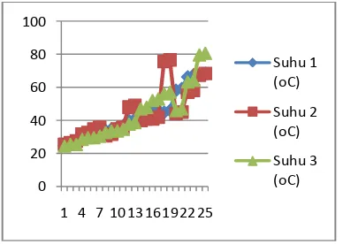
Fig 9. Measurement of the motor temperature sensor Composite 1, 2 and 3
From the experimental results can be seen that each sensor temperature sensor either 1, 2 and 3 have been able to work well. At any increase in the motor temperature sensor, the sensor can respond to this demand with a computer program showed on the display. The red color on the results of the temperature monitoring system and analysis of the compressor motor. Temperature sensor placement system on the compressor shown in Fig 10. and the results of temperature sensor readings on the motor with the motor compressor testing on the good and bad are shown in Table 2
Fig 10. Experiment Measurement of the temperature in the Compressor Motor
Table 2. Temperature sensor readings on the motor with the motor compressor testing on the
good and bad Condition
Temp compressor motor is detected that the temperature conditions in the motor that has a bad condition tend to be patterned rose or higher than the motor with Good condition.
700
Fig 11. Testing of vibration sensors on the electric motor
Programs are created using Labview
programming language. Photos how to test the vibration sensor on the electric motor and the display program shown in Fig 11 and Views vibration monitoring system program with Labview software shown in Fig 12.
Fig 12. Views vibration monitoring system program with Labview software
Until the time of writing this paper the research is still ongoing. Research lasted for 2 years. The first year focuses on the temperature sensor and the second year focuses on the vibration sensor. the testing of vibration sensors is still in the testing phase for each sensor to obtain the performance of the vibration sensor
5.CONCLUSION
1. After doing the design, manufacture and testing of the electric motor temperature and vibration monitoring based computer then obtained that the tool has been able to work as expected.
2. On testing shows that the temperature
monitoring devices will be able to detect if there is any discrepancy in the motor which will cause a rise in temperature, if such increases exceed the limit that has been setup then the tool will turn on the alarm and blinker.
3. The results of this study can be used to help detect early occurrence of early damage to the
electric motor which can cause the
temperature pattern that tends to rise and unstable, so that it can endorse the program of maintenance on the electric motor.
ACKNOWLEDGMENT
With the completion of this research, the authors would like to thank:
1. The Director General of Higher DP2M
Kemdikbud that has funded this research.
2. P3M STTNAS who have supported and
helped role in every stage of the research activities.
3. All Research Team Members and Students
help fully on result of design and manufacture to testing
REFERENCES
[1] E. Marwan and Wijianto, “Application
Vibration Response to analyze the
phenomenon of cavitation in centrifugal pump installation”, Research Journal of Science & Technology, Vol. 11, No. 2, UMS Surakarta, 2010
[2] E. T. Kiessel, “Industrial Electronic”,
International Edition Prentice Hall, Singapore, 1997.
[3] Miftahuddin, Yerri S., Aulia, S. A, ,
Identification of engine damage Spinning Based Voice Signal with the method of Adaptive Neuro Fuzzy Inference System, Repositionery, ITS Surabaya, 2010.
[4] Sumartono, “Predictive Maintenance at Pump
Unit Using Vibration Signals”, Proceedings of
the National Seminar Polban Bandung, 2012.
[5] Tugino, Direct Current Motor Speed Control
with Variable Voltage Based Computers, Thesis, STTNAS, Yogyakarta. 1994.
[6] W. Link. “Measurement Control and Settings
with PC”, Elek Media Komputindo, Jakarta,