23-28 Hardware Simulation of Rear-End Collision Avoidance System Based on Fuzzy
Logic
Noor Cholis Basjaruddin, Didin Saefudin, dan Anggun Pancawati
VOLUME 16 NOMOR 1
Jurnal
Rekayasa Elektrika
April 2020
JRE Vol. 16 No. 1 Hal 1-56 Banda Aceh,
April 2020 ISSN. 1412-4785
e-ISSN. 2252-620X
TERAKREDITASI RISTEKDIKTI No. 36b/E/KPT/2016
I. IntroductIon
Several types of collisions that often occur are side collisions, rear-end collisions and head-on (frontal) collisions. Rear-end collisions account for about 30%
of all collisions [1], [2]. Most rear-end collisions are caused by the negligence of the driver, at about 67% [3].
Technically, 45% of rear-end collisions are caused by the driver’s failure to brake or avoid the vehicle in front when it slows down or stops suddenly [1]. On the highway, rear- end collisions could potentially cause pile-ups that can involve tens or hundreds of vehicles.
The Rear-end Collision Avoidance System (RCAS) is designed to prevent rear-end collisions by taking over the functions of the driver when a collision will occur that for certain reasons, the driver was not trying to avoid [4], [5].
The manoeuvring of vehicles equipped with an RCAS to
avoid a rear-end collision involves setting the distance so that a safe distance is maintained or the car brakes to a stop when the vehicle in front stops suddenly.
Rear-end Collision Systems are also known as Pre-Safe Brake (Mercedes-Benz) [6], Forward Collision Avoidance Assist (Nissan), Collision Warning with Auto Brake (Volvo) [7] and Automatic Emergency Braking (Hyundai).
Some vehicles equipped with an RCAS include Mercedes- Benz CLA and E-class, BMW series 5 and 6, Cadillac CTS and XTS, the Audi A3 and A6, Hyundai Genesis and Toyota Avalon [8].
The focus in RCAS research is the development of algorithms and sensors. Some studies developed RCAS algorithms, among others [9], [10], while others researched the RCAS sensor [11], [12] and driver behaviour when a rear-end collision occurs, among others [13]. The development of RCAS as a subsystem of ADAS and the
Hardware Simulation of Rear-End Collision Avoidance System Based on Fuzzy Logic
Noor Cholis Basjaruddin, Didin Saefudin, Anggun Pancawati Jurusan Teknik Elektro, Politeknik Negeri Bandung
Jl. Geger Kalong, Ds. Ciwaruga, Bandung 40012 e-mail: noorcholis@polban.ac.id
Abstrak—Tabrakan sundulan adalah jenis kecelakaan lalu lintas yang paling umum. Di jalan raya, tabrakan ini mungkin melibatkan lebih dari dua kendaraan dan menyebabkan tabrakan berantai. Mengacu pada data yang dikeluarkan oleh Australian Capital Territory (ACT), tabrakan sundulan yang terjadi sepanjang 2010 sebanyak 43,65% dari seluruh tabrakan. Pada kebanyakan kasus, tabrakan sundulan disebabkan oleh pengemudi yang lalai, kondisi jalan yang buruk, dan jarak antar kendaraan yang terlalu dekat. Rear-end Collision Avoidance System (RCAS) adalah perangkat untuk membantu pengemudi menghindari tabrakan sundulan. RCAS adalah subsistem dari Advanced Driver Assistance Systems (ADASs) dan menjadi bagian penting pada mobil tanpa pengemudi. Pada artikel ini dibahas simulasi perangkat keras RCAS berdasarkan logika fuzzy menggunakan mobil remote control.
Metode Mamdani digunakan sebagai sistem inferensi fuzzy dan direalisasikan dengan menggunakan sistem mikrokontroler Arduiono Uno. Hasil simulasi menunjukkan bahwa algoritma logika fuzzy RCAS dapat bekerja sesuai dengan desain.
Kata kunci: sistem pencegah tabrakan sundulan, rear-end collision avoidance system, fuzzy logic, driver assistance system
Abstract—Rear-end collisions are the most common type of traffic accident. On the highway, a real-end collision may involve more than two vehicles and cause a pile-up or chain-reaction crash. Referring to data released by the Australian Capital Territory (ACT), rear-end collisions which occurred throughout 2010 constituted as much as 43.65% of all collisions. In most cases, these rear-end collisions are caused by inattentive drivers, adverse road conditions and poor following distance. The Rear-end Collision Avoidance System (RCAS) is a device to help drivers to avoid rear-end collisions. The RCAS is a subsystem of Advanced Driver Assistance Systems (ADASs) and became an important part of the driverless car. This paper discusses a hardware simulation of a RCAS based on fuzzy logic using a remote control car. The Mamdani method was used as a fuzzy inference system and realized by using the Arduiono Uno microcontroller system. Simulation results showed that the fuzzy logic algorithm of RCAS can work as designed.
Keywords: rear-end collision avoidance system, fuzzy logic, driver assistance system
Copyright © 2020 Jurnal Rekayasa Elektrika. All right reserved
Received 1 December 2019; Revised 6 February 2020; Accepted 7 February 2020
24
driverless car is also related to the development of other ADAS subsystems such as the Automatic Braking System (ABS) [14], Adaptive Cruise Control (ACC) [15], Lane Keeping Assist System LKAS [16], [17], and Overtaking Assistant System (OAS) [18].
In the era of connected vehicles, an RCAS was developed into a Cooperative RCAS (CRCAS), which is an RCAS which works not only using sensors, but also with communication between vehicles, known as V2V communication. The development of an RCAS into a CRCAS was among others conducted in [19] and [20].
II. research Method
The working principle of RCAS is the distance and speed monitoring of the vehicle in front of using the sensor. When the distance is too close compared to a safe distance, the vehicle will slow down or stop if the vehicle in front stops suddenly. In the following discussion, the term following vehicle (FV) refers to a vehicle equipped with RCAS and leading vehicle (LV) refers to a vehicle driving in front of the FV in the same lane.
A. The Problem of Rear-End Collision
An illustration of rear-end collision can be seen in Fig.
1. The acceleration, velocity and position of the FV car are aF(t), vF(t) and xF(t), while acceleration, velocity and the position of the LV car are aL(t), vL(t), and xL(t). The distance between the FV and LV is R(t).
Rear-end collisions can occur with the following scenarios:
1. The LV brakes and the FV is unable to brake or avoid and then hits the LV.
2. The LV is running at a normal speed and the FV at high speed, so that it hits the LV.
A rear-end collision can occur if R(t) ≤ 0, in which R(t) is the distance between the FV and LV. To avoid a rear-end collision, the FV must manoeuvre by reducing its speed or coming to a stop.
Basically, the RCAS is a system that allows the vehicle to be able to slow down or brake to a stop to avoid a rear- end collision automatically. Slowing or stopping suddenly both require a sufficient distance to process, which is called the safe distance (Sd).
Rear-end collisions can occur because the distance between the FV and LV is smaller than a safe distance and the situation is not corrected. The distance insufficiency is due to limited driver or environmental influences such as
weather and road conditions. The size of the vehicle can also result in a safe distance not being monitored well in large vehicles such as buses and trucks.
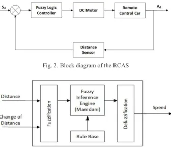
B. Block Diagram of RCAS
A block diagram of RCAS is shown in Fig. 2, in which Sd is a safe distance between the FV and LV, and Ad is the actual distance between the FV and LV, monitored by a distance sensor. If Ad is smaller than Sd, then the controller (Fuzzy Logic Controller, FLC) will choose how to avoid a collision with the LV. If it is still possible to adjust the distance, then the FV will brake and if it is not possible, then the FV will fully brake to a stop.
C. Fuzzy Logic-Based RCAS
The use of fuzzy logic for controlling a mobile robot has been carried out in studies [15], [21], and [22]. A block diagram of the fuzzy logic-based RCAS is provided in Fig. 3.
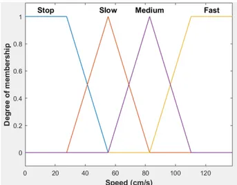
The input membership functions of the fuzzy logic- based RCAS can be seen in Fig. 4 and Fig. 5. The membership function of the distance input was divided into three regions, which were near, medium and far. The membership function of the change of distance input was divided into three regions, which were small, medium and big.Fig. 6 shows that the membership function of output was divided into three regions, which were slow, medium, and fast. The output variables were Pulse Width Modulation (PWM) values, indicating the desired speed.
The fuzzy rule base used can be seen in Table 1.
A view of the rule viewer of FLC is presented in Fig.
7. This view was selected at a distance situation in which the FV and LV are too close and the change of distances is big. The FLC output in this situation is stop. In such a situation, the FV should fully apply the brakes to stop. The output value is 38.2 on the display rules, indicating that the RC car stopped. The input and output relationship of the
Fig. 3. Block diagram of fuzzy logic-based RCAS Fig. 1. Illustration of rear-end collision
Fig. 2. Block diagram of the RCAS
Jurnal Rekayasa Elektrika Vol. 16, No. 1, April 2020
FLC can be seen in Fig. 8.
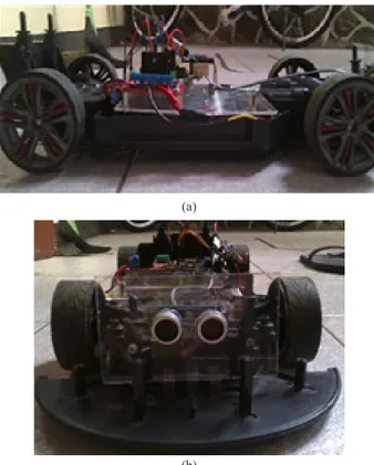
D. Hardware Simulation
A hardware simulation was built using a remote control (RC) car as shown in Fig. 9. The hardware simulation in this study used an ultrasonic sensor that was mounted on the front side of the car. The sensor was used to measure the distances of the LV from the FV. The low level of control in this study was simplified with an open loop speed control system based on PWM.
The RC car was used as the primary simulator device.
This RC car had a 1:10 scale of the real car. In the hardware simulation, an ultrasonic sensor was mounted on the front of the RC car. The sensor was used to measure the distance
of LV cars in front of the RC car.
The RC car was controlled using an Arduino Uno R3 microcontroller system based on ATmega328. The microcontroller system was equipped with a fuzzy logic library with Mamdani Min-Max as an inference method and defuzzification process using the centre of the area.
The control signal of the main motor in the RC car was made by using a PWM signal. Through the PWM signal, the speed of RC car could be determined as needed.
Important data during the testing process were stored in the Secure Digital (SD) card.
Fig. 4. Membership function of distance
Gambar 6. Membership function of output
Fig. 8. Graph of input and output relationship Tabel 1. Fuzzy rule base
Fig. 5. Membership function of change of distance
Fig. 7. View of the rule viewer Change of distance
Distance
Small Medium Big
Near Slow Stop Stop
Medium Slow Slow Stop
Far Fast Fast Medium
26
III. resultsand analysIs
Hardware simulation testing was divided into two sections. The first section was the subsystem testing, while the second section was the overall system testing.
A. Subsystem testing
Subsystem testing was performed on two sections, namely the proximity sensor and the speed control section of the RC car. The results of the proximity sensor measurements are presented in Fig. 10, whereas the relation speed of the RC car with the PWM value given to the DC motor of the RC car are provided in Fig. 11. It can be seen that if the voltage in the form of PWM given to the DC motor from the RC car is 150, then the RC car will go at a speed of 70 cm/s. The sensor measurements showed that the proximity sensor can measure the distance well.
Good sensor performance was necessary in this study,
because the distance was the input for the RC car speed control system.
B. Overall System Testing
Overall testing performed by using another RC car that acted as an LV, see Fig. 12. In the overall system, testing was performed using three variations of speed, which were slow, medium, and high speed.
Slow Speed and Stop Testing
The distance between the FV and LV was set to the close condition. At this time, the FV and LV were adjacent so that FLC output was slow if there were small changes in distance and FLC output stopped if the change of distance was medium or big. In the medium distance, the FLC output was slow if the distance changes were small and medium, while at big distance changes, the FLC output stopped. The test results are presented in Fig. 13 (a). A PWM value in the 0 to 150 range shows that the RC car drove at a slow speed or stopped. A PWM value below 100 indicates that the RC car stopped.
Medium Speed Testing
The distance between the FV and LV was set to far.
The speed of the FV changed to medium speed when distance changing was big. In this situation, the LV drove more slowly than the speed of the FV. This situation was addressed by a decrease in the FV’s speed to medium in order to avoid a rear collision. The test results are provided in Fig. 13 (b).
Gambar 12. System testing Fig. 11. PWM value vs. speed Fig. 9. Hardware simulator (a) side view (b) front view
Fig. 10. Proximity sensor performance (a)
(b)
Jurnal Rekayasa Elektrika Vol. 16, No. 1, April 2020
High Speed Testing
The speed of FV was high when the FV was away from the LV, as well as when the distance changing was small or medium. Testing was performed by adjusting the FV away from the LV. The test results can be seen in Fig. 13 (c).
When the FV was far from the LV, the FV sped up. Once the distance between the FV and LV was near, the speed of the FV decreased. A PWM value above 200 indicates the RC car was going fast.
I. conclusIon
Simulation using software showed that the FLC of RCAS can work well to control the speed of an RC car so that a rear-end collision can be prevented. Implementation of the hardware simulation using an RC car showed the FLC of RCAS can control the car’s speed to avoid a collision with the RC car in front. Improvements to the
performance of the RCAS algorithm, among others, can be achieved by adding input variables, namely the speed of the car in front. The addition of the input variables can refine RC car speed changes. In hardware simulation, the improvement can be achieved by increasing the distance range of the sensor and choosing a better RC car to improve the accuracy of the designed testing.
acknowledgeMent
This paper was funded by DRPM Grant 2019 (Contract Number: 151.8/PL1.R7/LT/2019) from Indonesian Ministry of Research, Technology, and Higher Education
referensI
[1] S. E. Lee, E. Llaneras, S. Klauer and J. Sudweeks, “Analyses of Rear-End Crashes and Near-Crashes in the 100-Car Naturalistic Driving Study to Support Rear-Signaling Countermeasure Development”, 2007.
[2] T. F. Golob, W. W. Recker and V. M. Alvarez, “Freeway safety as a function of traffic flow,” Accident Analysis and Prevention, vol.
36, p. 933–946, September 2004.
[3] J. M. Sullivan and M. J. Flannagan, “Risk of Fatal Rear-End Collisions: Is There More To It Than Attention?,” in The Second International Driving Symposium on Human Factors in Driver Assessment, Training and Vehicle Design, 2003.
[4] N. C. Basjaruddin, D. B. Margana, Kuspriyanto, R. Rinaldi and Suhendar, “Hardware Simulation of Advanced Driver Assistance Systems Based on Fuzzy Logic,” International Review on Modelling and Simulations (I.RE.MO.S.), vol. 11, no. 1, pp. 24- 31, 2018.
[5] K. Manjunath and N. Jaisankar, “A Survey on Rear End Collision Avoidance System for Automobiles,” International Journal of Engineering and Technology, vol. 5, no. 2, pp. 1368-1372, 2013.
[6] P. D. R. Schoeneburg, K.-H. Baumann and M. Fehring, “The Efficiency of PRE-SAFE®Systems in Pre-braked Frontal Collision Situations,” in National Highway Traffic Safety Administration, 2010.
[7] E. Coelingh, L. Jakobsson, H. Lind and M. Lindman, “Collision Warning With Auto Brake - A Real-Life Safety Perspective,”
2010.
[8] J. W. Jenness, N. D. Lerner, S. Mazor, J. S. Osberg and B. C.Tefft,
“Use of Advanced In-Vehicle Technology By Young and Older Early Adopter: Survey Results on Adaptive Cruise Control Systems”, 2008.
[9] M. Brannstrom, J. Sjoberg and E. Coelingh, “A situation and threat assessment algorithm for a rear-end collision avoidance system,” in IEEE Intelligent Vehicles Symposium, 2008.
[10] L. Yang, J. H. Yang, E. Feron and V. Kulkarni, “Development of a performance-based approach for a rear-end collision warning and avoidance system for automobiles,” in IEEE Intelligent Vehicles Symposium, 2003.
[11] K. Yamada, T. Ito and K. Nishioka, “Road lane recognition system for RCAS,” in IEEE Intelligent Vehicles Symposium, 1996.
[12] T. Kasuga and S. Yakubo, “Design of a Highly Safe Model Vehicle for Rear-End Collision Avoidance Considering Multiple Faults of Sensors,” in International Conference on Computational Intelligence, Modelling and Simulation, 2009.
[13] N. Hassan, H. Zamzuri, N. Wahid, K. A. Zulkepli and M. Z.
Azmi, “Driver`s Steering Behaviour Identification and Modelling Fig. 13. Slow speed testing result
(a)
(b)
(c)
28
in Near Rear-End collision,” Telkomnika, vol. 15, no. 2, pp. 861- 868, 2017.
[14] N. C. Basjaruddin, Kuspriyanto, Suhendar, D. Saefudin and V. A.
Azis, “Hardware Simulation of Automatic Braking System Based On Fuzzy Logic Control,” Journal of Mechatronics, Electrical Power, and Vehicular Technology, vol. 7, no. 1, pp. 1-6, 2016.
[15] N. C. Basjaruddin, Kuspriyanto, D. Saefudin and I. K. Nugraha,
“Developing Adaptive Cruise Control Based on Fuzzy Logic Using Hardware Simulation,” International Journal of Electrical and Computer Engineering (IJECE), vol. 4, no. 6, pp. 944-951, 2014.
[16] N. C. Basjaruddin, Kuspriyanto, D. Saefudin and A. Rachman,
“Hardware Simulation of Active Lane Keeping Assist Based on Fuzzy Logic,” Indonesian Journal of Electrical Engineering and Computer Science, vol. 5, no. 2, pp. 321- 326, 2017.
[17] N. C. Basjaruddin, Kuspriyanto, Suhendar, D. Saefudin and S. A.
Aryani, “Lane Keeping Assist System Based on Fuzzy Logic,”
in 2015 International Electronics Symposium (IES), PENS, 2015.
[18] N. C. Basjaruddin, Kuspriyanto, D. Saefudin, E. Rakhman and A. M. Ramadlan, “Overtaking Assistant System based on Fuzzy Logic,” Telkomnika (Telecommunication Computing Electronics and Control), vol. 13, no. 1, pp. 76-84, 2015.
[19] L. Li, G. Lu, Y. Wang and D. Tian, “A rear-end collision avoidance system of connected vehicles,” in IEEE 17th International Conference on Intelligent Transportation Systems (ITSC), 2014.
[20] X. Xiang, W. Qin and B. Xiang, “Research on a DSRC-Based Rear-End Collision Warning Model,” Transactions on Intelligent Transportation Systems, vol. 15, no. 3, pp. 1054-1065, 2014.
[21] M. A. P. Negara and D. S. Laksono, “Perancangan Kendali Robot pada Smartphone Menggunakan Sensor Accelerometer Berbasis Metode Fuzzy Logic,” Jurnal Rekayasa Elektrika, vol. 13, no. 2, pp. 76-81, 2017.
[22] R. Rendyansyah, A. P. P. Prasetyo and K. Exaudi, “Implementasi Fuzzy Logic dan Trajectory Pada Manipulator Mobile Robot Untuk Deteksi Kebocoran Gas,” Jurnal Rekayasa Elektrika, vol.
15, no. 1, pp. 18-24, 2019.
Jurnal Rekayasa Elektrika Vol. 16, No. 1, April 2020