Asia-Pac. J. Chem. Eng.2011;6: 760 – 770
Published online 14 March 2011 in Wiley Online Library (wileyonlinelibrary.com)DOI:10.1002/apj.565
Special theme research article
Exergy analysis and flowsheet modification of PT. PUSRI II
Palembang’s reformer unit for the production of synthesis
gas from natural gas
Muhammad Djoni Bustan,1* Shuhaimi Mahadzir2and Dian Kharismadewi1 1Chemical Engineering Graduate Program, University of Sriwijaya, Palembang 30139, Indonesia
2Chemical Engineering Department, Universiti Teknologi Petronas, Bandar Seri Iskandar, Trononh 31750, Perak, Malaysia
Received 28 July 2010; Revised 12 January 2011; Accepted 23 January 2011
ABSTRACT: Several processes which produce synthesis gas from natural gas have been analyzed by the exergy method. To minimize the exergy losses associated to chemical reaction, it is important to manage the exergy losses through the analysis, reconsidering the chemical path. A generally applicable and schematic way of performing exergy analysis and dealing with their results are illustrated. It is integrated to the modified flowsheeting reformer. As petrochemical industry in Indonesia, PT. Pupuk Sriwijaya II Palembang uses natural gas as a raw material to produce synthesis gas through the primary and the secondary reformers in a series. In the modified flowsheeting reformer, partial oxidation process has been added before the primary reformer and the secondary reformer has been eliminated from the process pathways. The exergy method of analysis has been implemented for each process, in order to calculate the exergies of the material streams along with the energy and mass-balance calculations both in the modified flowsheeting reformer and in a series process of the primary and the secondary reformers. And, the results of the calculations of the modified flowsheeting reformer in the process proposed modification are then compared to the results of the calculations of the series process of reformers in the existing conventional process. From the analysis, the overall exergy losses in a series process of the primary and secondary reformers can be reduced until 61.33%, by applying the modified flowsheeting reformer.2011 Curtin University of Technology and John Wiley & Sons, Ltd.
KEYWORDS: exergy analysis; flowsheet modification; reformer unit; partial oxidation; synthesis gas; natural gas
INTRODUCTION
Indonesia, as an agricultural country, still considers the agricultural sector as a significant contributor to its economy besides the growing industrial sector. Petro-chemical is one of the industries, which is still develop-ing in this country. PT. Pupuk Sriwijaya (PUSRI) II is the largest petrochemical plant in Palembang, Indone-sia that produces fertilizers for the large agricultural sector.
In the production of fertilizers, natural gas is used as a raw material to generate synthesis gas as a base for forming ammonia and urea fertilizer. Synthesis gas is produced in the primary and the secondary reformer units. The two reformers require large amount of fuel and heat to achieve a synthesis gas conver-sion of only around 97.8%. In addition, exergy analysis
*Correspondence to: Muhammad Djoni Bustan, Chemical Engineer-ing Graduate Program, University of Sriwijaya, Jalan Padang Selasa No. 524 Bukit Besar, Palembang 30139, Indonesia.
E-mail: [email protected]
around the reformers in PT. PUSRI II shows that the exergy losses are definitely high. In this study, modification of the process through flowsheet simu-lation of reformer is been explored, in which a par-tial oxidation process has been added before the pri-mary reformer. The secondary reformer has been elim-inated from the process pathways. The flowsheet sim-ulation enables the optimum process condition to be determined and the process with the minimum exergy losses for the production synthesis gas production to be selected.
EXERGY ANALYSIS METHOD
The method of exergy analysis is based on the second law of thermodynamics and the concept of irreversible production of entropy.[1] The method has found early development and application in the Soviet Union and Europe, primarily Germany and Poland. The earliest use of the word exergy has been attributed to Rant in 1956 by Bosjnakovic (1960), Trepp (1961) and Baehr
(1962). Exergy has been generally referred to as work capacity or available work. The concept was initially introduced by Gibbs and Helmholtz for thermodynamic analysis of chemical systems. A review on the use of exergy in systems analysis since its early beginning has been provided in the early millennium year.[2] Bosn-jakovic (1960) demonstrated the exergy analysis method on a power plant using the enthalpy–entropy diagram to present his results. He also made reference to the ben-efit of using exergy analysis in other related systems. Trepp (1961) examined exergy losses in refrigeration machines and develop optimum low temperature cycle design. Beahr (1962) provided an extensive discussion on exergy and presented his analytical results by com-paring flowcharts of exergy and energy.
Szargut (2005) mentioned that exergy analysis is based upon the second law of thermodynamics which stipulates that all macroscopic processes are irre-versible. Every such irreversible process entails a non-recoverable exergy lost, which is expressed as the prod-uct of the environment temperature and the entropy generated. The quantity of entropy generated is the sum of the values of the entropy increase for all the bodies taking part in the process.[3]The elementary irreversible phenomena that generate entropy are mechanical or hydraulic friction, heat transfer with a finite tempera-ture gradient, diffusion with a finite gradient of con-centration, and the mixing of substances with different parameters and chemical composition.
EXISTING CONVENTIONAL PROCESS
In the conventional process at PT. PUSRI II, natu-ral gas is converted into synthesis gas through steam reformers. The essential configuration of the pri-mary steam reformer is first established by Badis-che Anilin and Soda Fabrik (BASF) at the end of 1920s and the technology was used in 1931 by Stan-dard Oil of New Jersey to produce hydrogen from off-gases at its refineries. Since then, the process has been improved such as by M.W. Kellog at PT. PUSRI II.
In this work, process used by PT. PUSRI II Palem-bang would be as reference process in modification design and calculations analysis. This reference process, labeled as process A, uses a primary and a secondary reformer in series as shown in Fig. 1. Natural gas, as feed for the reforming process in the primary reformer, enters the feed preparation step where a heavy hydro-carbon and suspended particles are removed. Natural gas feed to the primary reformer consists of 81.90% CH4 by volume and other higher hydrocarbons with 5.45% C2H6, 2.87% C3H8, 0.44% i-C4H10, 0.56% n-C4H10, 0.15% i-C5H12, 0.08% n-C5H12, 0.03% C6+,
0.20% CO2, 0.01% Ar, 1.63% N2, and 6.68% H2. In addition, CO2 removal, dehydration, and desulfur-ization are also applied to the feed gas. Natural gas feed is then preheated to 430◦C and pressured to
33.87 atm before entering radiant section of the primary
FEED PREPARATION
FEED PREHEAT COIL
RADIANT SECTION (Tube Catalyst Ni)
SYNGAS PREPARATION SECONDARY REFORMER
(Tube Catalyst Ni) CONVECTION SECTION
(Coils)
Natural Gas Fuel Air
Steam Flue Gas
Exhaust to stack
Heat
Heat to utility
Flue Gas
Flue Gas
Air Heat (Flue Gas)
PRIMARY REFORMER T = 703.15 K
P = 33.87 atm
T = 1088.15 K P = 31.82 atm
T = 1251.15 K P = 30.72 atm
T = 644.15 K P = 35.50 atm
reformer. Energy from the hot flue gas is recovered in the convection section to raise steam or for other uses.
In the radiant section, previously natural gas feed is mixed with saturated steam to give methane-to-steam ratio of 1 : 4.25 then reacts in endothermic reaction with Ni-catalyst in a tubular reactor of the radiant section of the primary reformer at 815◦C,
31.82 atm. To increase and enrich the synthesis gas output from the primary reformer, the secondary reformer is then applied with air supply and the operating condition is 1251.15◦K, 30.72 atm. Its
syn-thesis gas reacts in exothermic reaction in the sec-ondary reformer with Ni-catalyst supported in a tubu-lar reactor then enters the synthesis gas preparation steps.
Conversion of CH4in the primary reformer of the nat-ural gas feed only reaches to 51.69%, while all heavier hydrocarbons in the natural gas feed are completely con-verted. In the secondary reformer, conversion of CH4is 95.48%. Consequently, the overall conversion of CH4 from the series reformers reaches to 97.82%.
Large amount of energy is consumed to raise the process temperature from preparation step to 815◦C in
the primary reformer and to 978◦C in the secondary
reformer. The overall energy consumed from both processes is 237 534.61 kJ h−1.
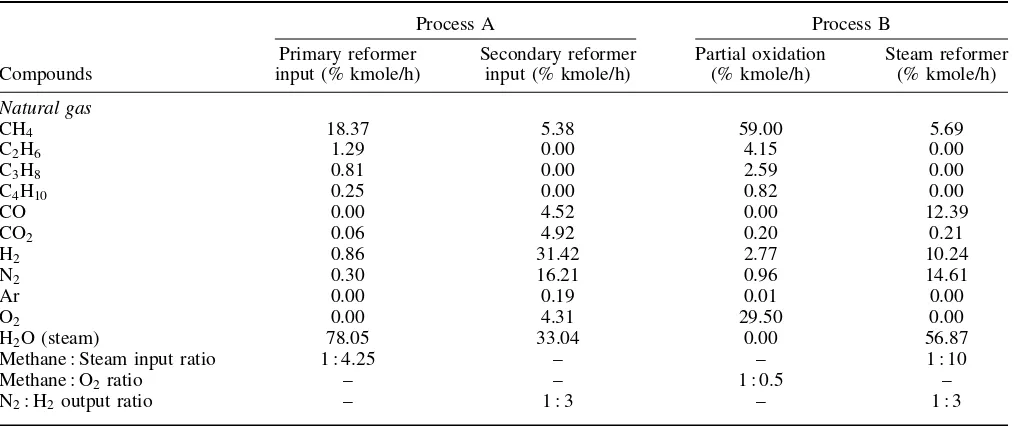
Material streams in processes A and B of this study (based on data of January 2009), could be seen from Table 1, for our focus on a synthesis zone of each block diagram.
The calculation of the material and energy balances are given in Table 3 and are based on the previous study about natural gas conversion and will not be discussed here, and only the calculation steps and results are showed in this article. The exergy losses of process
A in every step are shown in Table 4. It is shown that the exergy lost in process A is high. Clearly, although the overall conversion for the reforming could reach up to 97.82%, the consumption of energy, fuel, and the exergy losses in this process are definitely high because these parameters have not been optimized in the design.
PROPOSED PROCESS MODIFICATION
Exergy analysis with a flowsheeting simulator for syn-thesis gas production from natural gas to become methanol as a final product has been learned by Hin-derink et al.[4,12] In their method, they have imple-mented a set of external subroutines that have been integrated with a flowsheeting simulator, in order to calculate exergies of material streams along with the traditional energy and mass-balance calculations. They proposed four different pathways for the process: con-ventional steam reforming, concon-ventional steam reform-ing and pre-reformer; combined reformreform-ing with a nat-ural gas bypass, and convective reforming parallel to non-catalytic partial oxidation.
Run from those types of pathways as reference by using the operating condition and material streams similar to process A in our work, we have calculated its conversion and exergy analysis of each process which would not be discussed and compared in this article. Material streams input in the synthesis part of those processes are similar to process A, which is shown in Table 1 for primary reformer input at temperature 703.15 K and pressure 33.87 atm.
The block diagram of each process is shown in Fig. 2 for conventional steam reforming process (a) and
Table 1. Material streams of processes A and B.
Process A Process B
Compounds
Primary reformer input (% kmole/h)
Secondary reformer input (% kmole/h)
Partial oxidation (% kmole/h)
Steam reformer (% kmole/h)
Natural gas
CH4 18.37 5.38 59.00 5.69
C2H6 1.29 0.00 4.15 0.00
C3H8 0.81 0.00 2.59 0.00
C4H10 0.25 0.00 0.82 0.00
CO 0.00 4.52 0.00 12.39
CO2 0.06 4.92 0.20 0.21
H2 0.86 31.42 2.77 10.24
N2 0.30 16.21 0.96 14.61
Ar 0.00 0.19 0.01 0.00
O2 0.00 4.31 29.50 0.00
H2O (steam) 78.05 33.04 0.00 56.87
Methane : Steam input ratio 1 : 4.25 – – 1 : 10
Methane : O2ratio – – 1 : 0.5 –
FEED PREPARATION
FEED PREHEAT COIL
RADIANT SECTION (Tube Catalyst Ni)
SYNGAS PREPARATION CONVECTION SECTION
(Coils)
Natural Gas Fuel Air
Steam Flue Gas
Exhaust to stack
Heat
Flue Gas
Flue Gas
Heat (Flue Gas)
PRIMARY REFORMER
AIR SEPARATOR Oxygen
Fuel Air Flue Gas
Nitrogen Air FEED PREPARATION
FEED PREHEAT COIL
RADIANT SECTION (Tube Catalyst Ni)
SYNGAS PREPARATION PARTIAL OXIDATION
(Tube Catalyst Rh) CONVECTION SECTION
(Coils)
Natural Gas Fuel Air
Steam Flue Gas
Exhaust to stack
Heat
Heat to utility Flue Gas
Flue Gas
Heat (Flue Gas)
PRIMARY REFORMER Natural Gas
Figure2. (a) Block diagram of the conventional steam reforming process (A). (b) Block diagram of the combined reforming with natural gas baypass process (B).
combined reforming with a natural gas bypass pro-cess (b).
From these two processes (Fig. 2(a) and (b)), it is known that both processes give no satisfied conversion of methane and yield of hydrogen and carbon dioxide gas compared to process A as reference and also high in exergy losses.
On the basis of those processes results of calcu-lations learned before and its weaknesses and also
FEED PREPARATION
FEED PREHEAT COIL
PARTIAL OXIDATION (Tube Catalyst Rh)
STEAM REFORMER (Tube Catalyst Ni)
SYNGAS PREPARATION
AIR SEPARATOR
CONVECTION SECTION (Coils)
Natural Gas Fuel Air
Oxygen Natural
Gas Fuel
Air
Flue Gas
Exhaust to stack
Steam Steam
Nitrogen
Air T = 703.15 K
P = 33.87 atm
T = 1173.15 K P = 20 atm
T = 773.15 K P = 20 atm
T = 664.15 K P = 35.50 atm
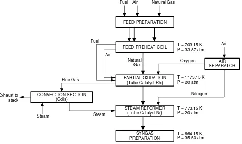
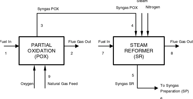
Figure3. Block diagram of the modified flowsheeting reformer, process (B).
below, while the block diagram for calculating exer-gies of the material streams is shown in Fig. 3. The operating conditions are taken from the previous study.[5]
Figure 3 illustrates the major process steps of the modified flowsheeting reformer in a block diagram. The partial oxidation process has been added before the primary reformer and the secondary reformer eliminated in process B. Natural gas with the same characteristics and compositions with process A supplies as a feed for the partial oxidation process, previously it will enter the feed preparation steps. In this first step, heavy hydrocarbon and suspended particles separation, CO2 removal and dehydration process are applied to the natural gas feed. Similar to the process A, natural gas feed is then preheated to the temperature of 430◦C in
the feed preheat coils and pressured to 33.87 atm, to enter the partial oxidation process. Natural gas feed is then mixed with limited oxygen to give methane-to-oxygen ratio of 1 : 0.5 and reacts in exothermic reaction with Rh-catalyst in a tubular reactor of the partial oxidation,[6,7]at the operating condition 900◦C, 20 atm.
To increase and enrich the synthesis gas output from the partial oxidation, synthesis gas output is then mixed with steam in methane-to-steam ratio of 1 : 10 in the primary/steam reformer at the operating condition 500◦C, 20 atm. Its synthesis gas reacts in exothermic
reaction with Ni-catalyst supported in a tubular reactor of the primary reformer. Nitrogen has been added in the primary/steam reformer in this process because in
the process A as a reference condition to the next step to produce ammonia, nitrogen is needed with ratio of N2-to-H21:3.
Material streams in this modified flowsheeting reformer (process B) could be seen from Table 1 pre-viewed before, for focus in a synthesis zone of Figure 3 block diagram. Material streams of natural gas feed compositions in process B are same as process A.
EXERGY CALCULATIONS OF THE MATERIAL STREAMS
The overall reactions and their standard Gibbs energy of reactions presented for the conversion of natural gas to synthesis gas for each process, is determined in Table 2.[8,9]
In Table 2, the minus of standard Gibbs energy of the overall reaction is denoted as available reaction exergy. It plays an important role in understanding the exergy losses associated to chemical reactions.
Table 2. The overall reactions.
Process Reactions G0r298K(kJ kmole−1)
A 1. In the primary reformer, from natural gas to synthesis gas
CH4 +H2O⇔CO+3H2 141 863
C2H6 +2H2O⇔2CO+5H2 214 661
C3H8 +3H2O⇔3CO+7H2 298 499
C4H10 +4H2O⇔4CO+9H2 349 042
CO+H2O⇔CO2 +H2 −28 618
2. In the secondary reformer, from synthesis gas to enriched synthesis gas
CH4 +H2O⇔3H2 +CO 141 863
2H2+O2 ⇔2H2O −457 144
CO+O2 ⇔2CO2 −651 549
B 1. In the catalytic partial oxidation, from natural gas to synthesis gas
2CH4+ O2 ⇔2CO+4H2 −86 709
C2H6 +O2 ⇔2CO+3H2 −242 483
2C3H8 +3O2 ⇔6CO+ 8H2 −387 217
C4H10 +2O2 ⇔4CO+5H2 −565 246
2CO+ O2 ⇔2CO2 −257 190
2. In the steam reformer, from synthesis gas to enriched synthesis gas
CH4 +H2O⇔CO+3H2 141 863
CO+H2O⇔CO2 +H2 −28 618
To calculate the equilibrium mixture for multi-reaction equilibria, we need the equilibrium constant K for the reaction, and is shown in Eqn (1).
−RT ln K=
i
υiGi0≡G
0
(1)
The final term G0 is the conventional way of rep-resenting the quantity
iυiGi0. It is called the standard Gibbs energy change of reaction. The function ofG0 is the difference between the Gibbs energies of the products and reactants (weighted by their stoichiomet-ric coefficients) when each species in its standard state as a pure substance at the system temperature and at a fixed pressure. Thus, the value of G0 is fixed for a given reaction once the temperature is established and is independent of equilibrium pressure and composition. And,G0/RT could be explained by Eqn (2). Integral Differential Heat Capacity for Enthalpy Calculations (ICPH) and Integral Differential Heat Capacity for Entropy Calculations (ICPS) are symbols for computational purposes as described in Eqns (3) and (4).
The evaluation of the integral∫CpdT is accomplished by substitution for Cp, followed by formal integration, for temperature limits ofT0 and T, where
τ = T
T0
(5)
Thus, G0/RT (= −ln K) as given by Eqn (2) is readily calculated at any temperature from standard heat of reaction and the standard Gibbs energy change of reaction at a reference temperature, T0 (usually 298.15◦K) and from two functions which can be calculated by standard computational procedures.
When two or more reactions proceed simultaneously, mole fractionsyi of the species are related toεor called reaction coordinate, characterized the extent or degree to which a reaction has taken place, shown by Eqn (6).
yi =
association with both a species and a reaction. Thus, υi,j designates the stoichiometric number of species i in reactionj.
And, when the equilibrium state in a reacting system depends on two or more independent chemical reac-tions, the equilibrium composition can be found by a direct extension of the methods developed for single reactions. If the equilibrium mixture is an ideal gas, it may be written as Eqn (7), whereP0=1 atm.
The mole fractions in Eqn (7) may be solved by using the mathematical program for the multireaction equilibria such Maple 11.
Heat requirements of the process (Q) are expressed by the summation of heat input to the reaction pro-cess and the heat of reactions itself as shown in Eqns (8) and (9), respectively.
Q=Qinput+Qreactions (8)
0 is heat of reaction at reference temperatureT0.
In calculating exergies of the material streams, the following steps of calculating were performed and adopted from Ahern.[3] A primary use of the exergy analysis is to show the location, type, and magnitude of the exergy losses, in a system.[11]As a result, the system efficiency can be effectively increased by reducing these losses. The exergy losses are generated throughout the system by irreversible production of entropy caused by the non-ideal performance inherent in all real systems and components.
The exergy lost results from heat loss during combus-tion could be calculated by using Eqn (10). This was assumed to be (1 - overall efficiency) and considered as a direct exergy loss as it reduced the available work in the fuel by that amount.
Exa =Qrelease of fuel×(1−overall efficiency)
×mole of fuel (10)
The exergy of fuel is Ex1,7 the heat release from natural gas fuel to the furnace.
Exergy lost resulting from transfer of chemical energy to heat energy is calculated using Eqn (11). During the
combustion of the fuel, the remainder of the chemical energy is transferred into thermal energy,
Ex2,8=(Qrelease of fuel×mole of fuel)−Exa (11)
A transfer of useful chemical energy into thermal energy is an irreversible process expressed by Eqn (12),
Exb =m9,4(Hout−Hin)
T0
Tg
(12)
The exergy loss resulting from a heat transfer between natural gas fuel and feed of process shows in Eqn (13).
Exc =T0(m9,4)
The total exergy loss of fuel natural gas to natural gas feed/synthesis gas in the process isExb+Exc.
Furthermore, the exergy loss during the outflow of synthesis gas of certain process in piping from one step process to the other is expressed in Eqn (14).
Ex3,5=(Hout−Hin)−T0(Sout−Sin) (14)
In Figs 4 and 5, a synthesis gas in conditions 4 and 6 has a work capacity, so
Ex4,6=(H4,6−H9,4)−T0(S4,6−S9,4) (15)
Moreover, the exergy lost in process is expressed by Eqn (16) below.
Exd =Ex3,5−Ex4,6 (16)
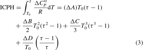
The exergy loss of friction from the partial oxi-dation to the steam reformer or from the primary reformer to the secondary reformer or from the steam reformer/secondary reformer to the synthesis gas prepa-ration is Figure 4 describes the material and energy calcula-tions steps in the proposed process modification. The composition moles input used is similar to the exist-ing conventional process A. It is divided into two big blocks, named 1 and 2.
Block 1 is the step for calculating material conversion and moles fraction of natural gas that reacts in a process. Furthermore, block 2 is the step for calculating the energy streams in a process that is continuing from steps in block 1.
Estimate the reactions occur in a process, variations temperature and fixed pressure
condition
Calculate ∆G°, ∆H° in standard reference temperature of 298 °K
Calculate ICPH and ICPS for all temperature variations and reactions
Calculate ∆G° for all temperature variations and reactions
Calculate K in all temperature variations and reactions
Calculate ξ (conversion) in each reaction with Maple 11 program
Calculate yi (mole fraction) for all components in reactions
Calculate Qinput, Qreactions
Calculate Qtotal = Qinput + Qreactions
Block 1
Block 1 ° °
Figure4. Block flow of calculation of material and energy streams.
process B for the same initial feed of a raw natural gas is shown in Table 3
Assumption has been taken for the conventional combustion temperature, which is 1927◦C and the
ambient temperature is 25◦C. The overall efficiency of
the furnace is 88% with heat release of the natural gas fuel is 15 189 Btu lb−1 based on the actual operating
condition at PT. PUSRI II reformer furnace. Natural gas fuel compositions consist of CH464.61%, C2H67.97%, C3H8 7.08%, i-C4H10 1.25%, n-C4H10 1.76%, i-C5H12 1.01%, n-C5H12 0.56%, and CO215.76% moles.
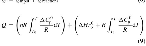
The exergy calculation of the material streams at each point of flows, based on the block diagram in the process descriptions, is described in Figs 5 and 6 for the related processes.
RESULTS AND DISCUSSION
The calculation of exergy at discrete points in a system will indicate the total exergy change, reversible and irreversible in the process and in the equipment between any two points. These exergy values are explicit values relative to the reference condition of the surrounding environment. On the basis of the calculation of exergy performed, the results of the exergy analysis are shown in Tables 4 and 5.
The overall reactions of natural gas feed occurs in the primary reformer is endothermic reaction, that con-sists of higher hydrocarbons reactions. From Table 4, it can be seen that the largest amount of the exergy lost is in the primary reformer that accounts for 95.17% of the total exergy lost in process A. The presence of high exergy lost in the primary reformer may indi-cate a poor match between the quality of the energy supplied to the process and the quality required by the process to perform a given task. This mismatch results in large irreversibility. Heat released by fuel of natural gas can reach temperature to 1927◦C through
the conventional combustion furnace, while the maxi-mum temperature required by the process only reaches 815◦C.
In the secondary reformer, the exergy loss is in the minimum percentage in which the temperature operation needed reaches 978◦C for the exothermic
reaction occurred with large amounts of moles input and heat used. Although the exergy values always
PRIMARY REFORMER
(PR)
SECONDARY REFORMER
(SR)
Fuel In Flue Gas Out Fuel In Flue Gas Out Syngas PR Air
Steam Natural Gas Feed Syngas SR To Syngas
Preparation (SP) 1
3 4
9
2 7
5
6 8 Syngas PR
Table 3. Mass and heat input of the material streams.
Process
Total moles input (kmole h−1)
Total heat input (kJ h−1)
A 1. In the primary reformer, from natural gas to synthesis gas 5857.06 99 392 276.41 2. In the secondary reformer, from synthesis gas to enriched synthesis gas 9657.16 265 845 258.21 B 1. In the catalytic partial oxidation, from natural gas to synthesis gas 1823.88 34 765 753.39 2. In the steam reformer, from synthesis gas to enriched synthesis gas 7628.99 158 957 291.79
PARTIAL OXIDATION
(POX)
STEAM REFORMER
(SR)
Fuel In Flue Gas Out Fuel In Flue Gas Out
Syngas POX Steam
Oxygen Natural Gas Feed Syngas SR To Syngas
Preparation (SP) 1
3 4
9
2 7
5
6 8
Syngas POX Nitrogen
Figure6. Exergy analysis diagram of the modified flowsheeting reformer, process (B).
show positive to the reference surrounding environment, in the secondary reformer it shows negative value. The zero reference for enthalpy and entropy values in the literature often results in positive and negative values of exergy calculation for the system. Total exergy losses of the entire processes in process A are 2 821 615.23 MJ h−1, its amounts will reduce through the modified flowsheeting reformer which is shown in Table 5.
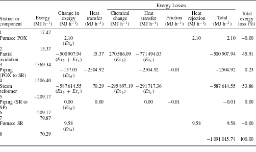
As shown in Table 5, the total exergy lost for the entire process B is 1 091 015.74 MJ h−1. The flowsheet modification of process A is done through replacement of the secondary reformer with a partial oxidation process upstream of the primary reformer. Process B shows a significant potential reduction in the total exergy lost in primary reformer (steam reformer) by up to 78.11% relative to the conventional process A. Furthermore, the operating conditions in the primary reformer of process B is reduced to 500◦C, 20 atm
thereby reducing the consumption of natural gas fuel in the reformer. Heat released from the exothermic partial oxidation process may be recovered to provide heating for the endothermic reaction in steam reformer of process B.
So, the overall exergy losses in process A can be reduced through applying a modification such in process
B, as much as
% exergy savings
=
exergy losses in process A−exergy losses in process B exergy losses in process A
×100%
=
2821615.23 MJ/h−1091015.74 MJ/h 2821615.23 MJ/h
×100% % exergy savings=61.33%
CONCLUSIONS
A
Table 4. The exergy analysis of the series reformers (process A).
Exergy losses
Furnace primary 5.99 5.99 5.99 −0.00
(Exa)
2 43.95
Primary reformer −2 685 274.29 43.95 −1 306 860.27 −1 378 414.01 −2 685 274.29 95.17
(Exb + Exc) (Exb) (Exc)
3 −1187.94
Piping 898.13 −156 418.00 −156 418.00 0.01 −156 417.99 5.54
(PR to SR) (Exd)
4 −2086.07
Secondary reformer 22 955.61 117.55 1 222 160.24 −1 199 204.63 22 955.61 −0.00
(Exb + Exc) (Exb) (Exc)
5 931.45
Piping −0.30 −2900.54 −2900.54 −0.05 −2900.59 0.10
(SR to SP) (Exd)
6 931.75
7 133.58
Furnace secondary 16.03(Exa) 16.03 16.03 −0.00
8 117.55
−2 821 615.23 100.00
Table 5. The exergy analysis of modified flowsheeting reformer (process B).
Furnace POX 2.10 2.10 2.10 −0.00
(Exa)
2 15.37
Partial −500 907.94 15.37 270 586.09 −771 494.03 −500 907.94 45.91 oxidation (Exb +Exc) (Exb) (Exc)
3 1369.34
Piping −137.05 −2504.92 −2504.92 −0.01 −2504.92 0.23
(POX to SR) (Exd)
4 1506.40
Steam −587 614.55 70.29 −295 897.19 −291 717.36 −587 614.55 53.86 reformer (Exb +Exc) (Exb) (Exc)
Furnace SR 9.58 9.58 9.58 −0.00
(Exa)
8 70.29
−1 091 015.74 100.00
in the primary reformer itself can be reduced to 78.11% relative to process A.
NOMENCLATURE
υ Stoichiometric number
ε Reaction coordinate
ρ2, ρ1 Density of components in the material streams at point 2 and 1, kg cm−3
H Total enthalpy of material streams, kJ
kmole−1
S Total entropy of material streams, kJ
kmole−1 G0, G0
0 Gibbs energy, standard Gibbs energy of pure component at 298.15◦K, J mole−1
m Mole input to the process, mole
ni,0 Mole of pure component; Mole total, mole
P2, P1 Pressure of process at point 2 and 1, atm
P0, P Reference pressure; Process pressure, atm
Q Heat, kJ h−1
R Universal gas constant, J mol−1 K−1
Tg The conventional combustion furnace
temperature, ◦K
T0 The ambient temperature, ◦K
T0,T Reference temperature; Process tempera-ture, ◦K
y Mole fraction
REFERENCES
[1] I. Dincer, M. Rosen. Exergy: Energy, Environment, and Sustainable Development, Elsevier: Oxford, United Kingdom, 2007.
[2] E. Sciubba, G. Wall.Int. J. Thermodyn.,2007;10(1), 1 – 26. [3] J.E. Ahern. The Exergy Method of Energy Systems Analysis,
John Wiley & Sons Inc: USA,1980.
[4] A.P. Hinderink, F.P.J.M. Kerkhof, A.B.K. Lie, J.D.S. Arons, H.J.V.D. Kooi.Chem. Eng. Sci.,1996;51(20), 4693 – 4700. [5] M.D. Bustan, S. Haryati, I.G. Mendera. Studi Analisis
Per-bandingan Antara Konvensional dan Modifikasi Flowsheeting Sistem Produksi Syngas Terhadap Konversi dan Penurunan Konsumsi Panas Pada Reformer PT. PUSRI II Palembang, Thesis, Sriwijaya University, Indonesia,2009.
[6] M.V. Twigg. Catalyst Handbook, Wolfe Publishing Ltd: England 2ndedn.,1989.
[7] S. Bharadwaj, L. Schmidt. Catalytic Partial Oxidation of Natural Gas to Syngas Fuel. Proc. Tech,1995.
[8] M.R. Felder, R.W. Rousseau.Elementary Principles of Chem-ical Processes, John Wiley & Sons Inc: USA,2005. [9] O. Levenspiel. Chemical Reaction Engineering, Wiley
East-ern: New Delhi,1999.
[10] J.M. Smith, H.C. Van Ness. Introduction to Chemical Engineering Thermodynamics, McGraw-Hill: New York, 1987.
[11] W.D. Seider, J.D. Seader, D.R. Lewin. Process Design Principles; Synthesis, Analysis and Evaluation, John Wiley & Sons Inc: USA,1999.