HIGH PRECISION TEXTURE RECONSTRUCTION FOR 3D SCULPTURE MODEL
Zhang Fan a, *, Huang Xianfeng a, Zhang Zhichao b, Fang Wei a, Li Deren a a
State Key Laboratory of Information Engineering in Surveying, Mapping and Remote Sensing, Wuhan University, Wuhan, 430079, China.
b
School of Remote Sensing, Wuhan University, Wuhan, 430079, China.
Commission V, WG V/2
KEY WORDS: Texture, Mapping, Image, Modeling, Reconstruction, Cultural Heritage, Laser scanning ABSTRACT:
High precision 3D sculpture model can take the accurate records of the shape, material and color on the surface of the sculpture. It is an important foundation work of digital documentation, preservation, archaeological research and analysis for the sculpture types of cultural heritage. Constructing high precision 3D sculpture model includes two aspects: geometry modeling and texture reconstruction. But, there are many urgent problems still existing in the method of high precision texture reconstruction. This paper discussed a method of high precision texture reconstruction based on non-rigid transformation for 3D sculpture model. First, coarse registration of texture image to geometrical model is conducted with direct linear transformation (DLT) method. Then, the registration is optimized with thin plane spline (TPS) function to reduce local matching errors between texture image and geometrical model. Finally, texture mapping is implemented with optimized registration result. The experiments based on the sculpture in Dunhuang Mogao Grottoes of China are conducted, and the efficiency and feasibility of the proposed methods are proved.
* Corresponding author E-mail: [email protected] 1. INTRODUCTION
Sculpture is one of the important forms of heritage and exists in great quantity in relics such as temples, towers and grottoes. 3D digitization with high accuracy provides an important mean for the protection of cultural heritage of sculpture, by taking the accurate records of the shape, material and color on the surface of sculpture. High accurate reconstruction of 3D sculpture model includes two aspects: geometry modeling and texture reconstruction. With the rapid development of laser scanning system and geometry data processing technology, high precision geometry modeling from laser scanning data has become feasible. On the other hand, there are many urgent problems still existing in the method of high precision texture reconstruction for 3D sculpture model. These problems are the bottleneck in 3D digital cultural heritage modeling.
Even though some scanner could generate color point cloud with the built-in camera or combination of multi-spectral backscattered intensity (Lyons et al., 2000), those color information are not suitable of texture reconstruction due to their low resolution. Currently, the general method of texture reconstructing with high quality is the accurate binding of camera-captured high definition image to 3D model using texture mapping(Gal et al., 2010; Tzur and Tal, 2009). And texture mapping is based on the registration of 3D geometric model and 2D texture image. The position of 3D model and 2D image can be modeled as pinhole, in which their relationship is defined as perspective centered by the optical center of the camera(Ma Songde, 1998).Therefore, most of researches on registration of 2D to 3D were focused on the recovery of spatial position of camera on the moment of image capturing, thus registered them by construction of perspective projection model. In all cases, one can basically follow three different approaches. 1) Calculating parameters of perspective projection from corresponding points selected on 3D model and 2D image
(Walkowski et al., 2008; Zha and Wang, 2003; Zhang et al., 2008; Diao Changyu, 2007). 2) Recovering the pose and position of camera by matching contours of objective within each 2D image to the silhouette of projected 3D model(Lensch et al., 2001; Neugebauer and Klein, 1999). 3) Conducting pure 3D registration between 3D model and 3D points generated from aligned stereo images(Deng Fei, 2006; Liu Gang, 2005). However, those above methods cannot satisfy the texture mapping of high accuracy, because they employ linear pinhole model to represent perspective projection relationship between 2D image and 3D model. This transformation model is rigid and neglects the lens distortion of camera, the inborn error of laser scanners and accuracy loss in data process. Therefore local matching errors will be found after rigid registration with above mentioned methods. In some methods, the lens distortion on the image is corrected using predefined calibration models(Diao Changyu, 2007) in which errors may still exist, but the errors of 3D model cannot be represented with rigid mathematical model, thus cannot be essentially eliminated with registration model based on rigid transformation.
This paper proposed a texture mapping method based on non-rigid transformation. First non-rigid coarse registration of 2D image to 3D model is conducted with direct linear transformation (DLT). Then the rigid registration is optimized under the principal defined with improved weighted thin plate spline function. Based on the optimization, which is also named non-rigid registration, 2D image can be accurately projected onto the 3D model thus finish texture mapping. This non-rigid registration method can achieve high accuracy globally and locally.
2. COARSE REGISTRATION BASED ON DLT
This paper employed DLT to construct the correspondence between points on 2D image and surface of 3D model and to
complete 2D-3D coarse registration. DLT needs no initial values of position for implementation, thus is very suitable for processing of images captured by non-metric cameras. And the linear relationship between 2D and 3D points imposes no difficulty on calculation of parameters.
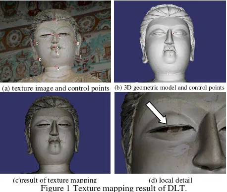
To avoid the instability of parameter solving, DLT requires 3D control points not on a plane. If those 3D points distributed almost on a plane or within a small area, parameter can be solved without high accuracy. Therefore controls point should be picked with different range level, the more different of the range to center of camera, the better. Furthermore, control points are better distributed evenly and fully on the image. Figure 1shows the texture mapping result of coarse registration based on DLT. Figure 1 (d) is the zoomed-in image of eye, obviously, DLT method creates mismatching in details. Therefore, non-rigid registration method is necessary for high accurate texture reconstruction.
Figure 1 Texture mapping result of DLT.
3. TEXTURE MAPPING BASED ON NON-RIGID TRANSFORMATION
The DLT-based rigid registration between texture image and 3D model the geometric is inaccurate in details, due to the error of geometric modeling, distortion of texture image, inaccuracy of control point and DLT. Given those consideration, non-rigid registration is necessary to be set up for more accurate mapping of texture image to surface of geometric model.
3.1 Thin plate spline function and its improvement
TPS is the only spline that can separate mapping into rigid and non-rigid (Chui and Rangarajan, 2003), under the constraint of one-to-one mapping of point sets, matching matrix and mapping parameters between point sets can be jointly solved with minimized bending energy function (Sun Dongmei, 2002). Thus, TPS has been widely used in non-rigid registration of medical images (Johnson and Christensen, 2002; Yang Jian, 2007; Zhang Yu, 2003).
In 3D coordinate system OXYZ, a thin metal plate F was placed in the XOY plane, and n control points with corresponding were set near F. Then, F was distorted under the constraints of these control points. Given the inherent physical properties of the metal plate, F should have a minimum bending energy at the equilibrium of deformation. Therefore, the deformed F can be expressed with the function , and this function should satisfy two conditions:
(1) At each control point, f(xi,yi)zi,(i1,2,,n);
(2) Minimized bending energy function J(f).
In reference (Bookstein, 1989), Bookstein defined the energy function J :
The form of function f that satisfy these conditions is::
should be placed on the candidate images, A and B, respectively, and the TPS function established by those control points can be divided into two sub-TPS functions (Feng Lin, 2005):
(, ), ( , )
) ,
(xy f xy f xy
fxy x y (3)
3.2 Weighted thin plate spline function
To reduce the impact imposed by deviations of control points on the TPS interpolation,TPS must be improved to be smooth to bring down the restraint of control points on TPS (Zhang Yu, 2003).
The n pairs corresponding control points set that to be registered are denoted as Pi and Qi,(i1,2,,n), and
u
denotes the smoothed TPS transformation function, so the mismatching error can be expressed as)
According to optimization theory, strictly constraint problems can be converted to non-constraint for the construction of function
u
, by introducing penalty function as below:
smoothness of TPS. Thus, standardly constructed TPS function can be converted to non-constraint problems by minimizing value of F in Formula (4), of which its meaning is minimized bending energy and maximized matching degree of the denoted points.In Formula (4), is used to adjust impact of the energy function
J and
on smoothing TPS function.
Smoothing TPS takes use of united value of to adjust constraint of all the control points. However, the position confidence of every control point is different and so does the constraints. Therefore, every control point should be weighted differently according to its confidence of position. The weighted TPS function proposed by Roman etc. can assign different weight to control point, and it was applied to reduce image noise (Kaspar and Zitova, 2003). When applied to weighted TPS function used for texture mapping, the formation and configuration of weight are also different.
Denotes the weighted TPS function as s, the penalty function
weight of matching degree of control point on penalty function is determined by the accuracy of control points. Greater ηi represents higher accuracy of control point, smaller (a) texture image and control points (b) 3D geometric model and control points
(c)result of texture mapping (d) local detail
correspondingh2(s)
i and a nearer distance between registered control points, vice versa.
In texture mapping, needed weighted TPS function can be constructed from Formula (5), by setting corresponding weight
i
η according to the confidence of control points.
3.3 Non-rigid texture mapping procedure
Texture mapping procedure based on weighted TPS is specified as follow:
(1) Select n pairs 2D-3D corresponding control point between image and model, and denoted them asP(Pi) and
), (Qi
Q (i1,2,,n). Meanwhile different weights η=(ηi) are
assigned according to the confidence gradient of control points. And the coefficient of DLT between image and geometric model is calculated with least square method.
(2) Calculate corresponding pointQi' on the surface of 3D
model by DLT for every control point Pi on image. Because of errors, Qi' does not coincide with Pi on the image. Denoting n d vectorQ'(Qi'),(i1,2,,n),the weighted TPS function s is
constructed with P、Q'and their corresponding weights η.
(3)Calculate texture coordinates for every vertex on 3D model using DLT parameter and weighted TPS function s generated from above. Specifically, transform the coordinates
) , ,
(XYZ of vertex on model to corresponding texture image coordinates (x,y) with DLT. Then transform texture coordinate
) ,
(xy into image coordinates (xt,yt) through weighted TPS
function s constructed in step (2). Finally, transformed image coordinates are normalized into texture coordinates (u,v) with size of texture imageRtex andCtex.
(4) Check if the texture mapping result on the 3D model needs to be adjusted. If it satisfactory, finish texture mapping, or adjustment in Step(5) will be needed.
(5)Select more control points and weight in area where the error of texture mapping is large, then add those control points to vector P, Q and η, and switch to Step (2).
4. TRANSMITTAL AND FURTHER INFORMATION EXPERIMENT AND ANALYSIS
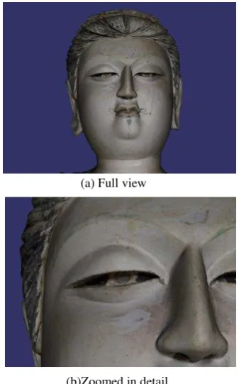
The Mogao Grottoes of Dunhuang lies on the ancient silk road in China, and contains large quantity of color sculptures which have a very high artistic value and cultural connotation and is one of the most representative cultural heritage. Some typical color sculptures are chosen to experiment the texture mapping and to test the validation of method proposed in this paper. Experiment 1 Generally, the corresponding controls points are selected based on texture image and geometric model. Experiment 1uses the face of sculptural Bodhisattva in Cave 196 for its obvious geometric feature. The non-rigid texture mapping of this dataset is presented in Section 2. And texture mapping based on non-rigid transformation is showed as Figure 2. By comparison of zoomed in eye in Figure 2(d)and
Figure 2(b), apparently this method can map texture with greater accuracy in details.
Figure 2. Result of non-rigid texture mapping of experiment 1.
Experiment 2 In some other cases, the surface of geometric model is too smooth to select 2D-3D control point accurate enough, whereas the intensity of point cloud can be used to facilitate the selection of controls points on 3D model. The color sculpture of Experiment 2 is a sitting Buddha in Cave 285, the texture image, geometric model and selected corresponding control points are displayed in Figure 3 as below. Because this sculpture is closely backed by wall on which some control points are selected for the sake of increasing range level of control points, obtaining larger area on image and solving more accurate DLT parameters.
(a) Full view
(b)Zoomed in detail
Figure 3. Data of experiment 2
The face of this sculpture was so severely damaged that much less features can be found on 3D model than sculpture in experiment 1, and it back wall is also very flat without geometric features. To select control points on such 3D model, intensity information displayed with pseudo-color is attached to 3D geometrical model. As showed in Figure 4, control points can be selected with features on the colored intensity without difficulty.
Figure 4 Overlapped display of intensity of point cloud and geometric model.
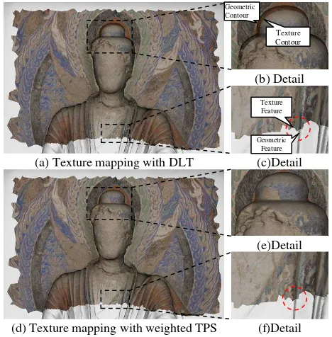
The texture mapping result of Experiment 2 is displayed in Figure 5, (a) and (d) are texture mapping results of rigid DLT and non-rigid weighted TPS. From the zoomed in image of chignon in Figure 5(b), obvious error can be found on the texture mapping result of DLT, noticeable offset exists between the contours of model and texture. However, in Figure 5(e) those contours coincide with each other after texture mapping of weighted TPS. Similar conclusion can also be made by comparison of Figure 5(c) and (f): the line features on the
texture and model clearly mismatch with each other within dash lines circle in Figure 5(c), while the accurately aligned in non-rigid texture mapping result in Figure 5(f).
Figure5. Comparison of texture mapping results based on DLT and weighted TPS in Experiment 2.
5. CONCLUSION AND PROSPECT
The distortion of texture images and errors in 3D geometric model frustrate the traditional rigid registration method on highly accurate texture mapping. And this paper proposed a method of texture mapping on laser scanning model, based on non-rigid transformation. At first, the method employs DLT to finish coarse registration of images to geometric model, then the weighted TPS function is used to restraint the deformation of texture, and finally, texture mapping is conducted based on the non-rigid registration of texture image to geometric model. This registration method accurately aligns the texture and model globally and locally. On the other hand, TPS function is weighted with function that enables the normalized gradient values to effectively manage the restraints of control points. Texture mapping experiment on multiple data set in conducted and those achieved good results demonstrate the effectiveness of this method.
Further study will be focused on the automation of control points selection by taking advantage of intrinsic feature of image and models, to automatically map texture with high quality.
Acknowledgments
This research was supported by National Science and Technology Support Program of China (2010BAK67B17), the National Basic Research Program of China (2012CB725301), the National Natural Science Foundation of China (41001308, 41071291),and the Natural Science Foundation of Hubei Province (2010CDB08405).
(a) Texture image and control points
(b) 3D geometric model and control points
(a) Texture mapping with DLT
(d) Texture mapping with weighted TPS
(b) Detail
(c)Detail
(e)Detail
(f)Detail
Geometric Contour
Texture Contour
Geometric Feature Texture Feature
Reference
Bookstein, F.L., 1989. Principal Warps: Thin-Plate Splines and the Decomposition of Deformations. IEEE Transactions on Pattern Analysis and Machine Intelligence, 11(6): 567-585.
Chui, H. and Rangarajan, A., 2003. A new point matching algorithm for non-rigid registration. Computer Vision and Image Understanding, 89: 114-141.
Deng Fei. Research on LiDAR and digital images registration and objects extraction (in Chinese). Dissertation of Doctoral Degree. Wuhan: Wuhan University, 2006 Feng Lin, Zhang Mingju, He Mingfeng, et al. A non-rigid
medical image registration approach based on hierarchical mutual information and thin-plate spline (in Chinese). Journal of Computer Aided Design & Computer Graphics, 2005, 17(7): 1492-1496
Gal, R., Wexler, Y., Ofek, E., Hoppe, H. and Cohen-Or, D., 2010. Seamless Montage for Texturing Models. Computer Graphics Forum (Proc. Eurographics 2010), 29(2): 479-486.
Johnson, H.J. and Christensen, G.E., 2002. Consistent Landmark and Intensity-Based Image Registration. IEEE Transactions on Medical Imaging, 21(5): 450-461.
Kaspar, R. and Zitova, B., 2003. Weighted Thin-Plate Spline Image Denoising. Pattern Recognition, 36: 3027-3030. Lensch, H.P.A., Heidrich, W. and Seidel, H.-P., 2001. A
Silhouette-Based Algorithm for Texture Registration and Stitching. Graphical Models, 63(4): 245-262. Lyons, P.D., Rioux, M. and Patterson, R.T., 2000. Application
of a Three-Dimensional Color Laser Scanner to Paleontology. Palaeontologia Electronica, 3(2): 1-16. Ma Songde, Zhang Zhengyou. Computer Vision(in
Chinese)[M]. Beijing: Science Press, 1998.
Neugebauer, P.J. and Klein, K., 1999. Texturing 3D Models of Real World Objects from Multiple Unregistered Photographic Views. Eurographics Workshop '99, 18(3): 245-256.
Sun Dongmei, Qiu Zhengding. A New Non-rigid Image Matching Algorithm Using Thin-Plate Spline[J]. ACTA Electronica Sinica, 2002, 30(8): 1104-1107 Tzur, Y. and Tal, A., 2009. FlexiStickers - Photogrammetric
Texture Mapping using Casual Images. SIGGRAPH 2009, ACM Transactions on Graphics, 28(3): 1-10. Walkowski, F., Johnston, R.A. and Price, N.B., 2008. Texture
Mapping for the FastSCAN hand-held laser scanner, Image and Vision Computing New Zealand, 2008. IVCNZ 2008. 23rd International Conference, pp. 1-6. Yang Jian, Wang Yongtian, Tang Songyuan etc. Elastic X-Ray
Image Registration Based on Mutual Information and Thin-Plate Spline. Acta Electronica Sinica, 2007, 35(1): 127-130
Zha, H. and Wang, P., 2003. Realistic face modeling by registration of a 3-D mesh model and multi-view color images, Proceedings of the 8th International Conference on CAD/Graphics, Macao, pp. 217-222. Zhang Yu, Liu Zhexing, Hao Liwei and Li Shuxiang. Medical
Image Elastic Registration Using Smoothing Thin-Plate Spline. Journal of Image and Graphics, China, 2003, 8(A)(2): 209-213
Zhang, Z., Huang, X., Zhang, F., Chang, Y. and Li, D., 2008. A semi-automatic multiple view texture mapping for the surface model extracted by laser scanning, International Conference on Earth Observation Data Processing and Analysis (ICEODPA 2008), Wuhan, China.