A3.1 Introduction
It has been shown that the conditions for equilibrium of a set of coplanar forces can be summarised in the three equations of
equilibrium (see Appendix 1). These equations can be solved as a simultaneous set for the forces in a force system which are unknown as was shown in connection with Fig. A1.9.
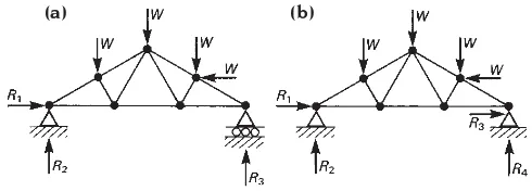
A structure which can be fully solved from the equations of equilibrium in this way is said to be statically determinate. The structure in Fig. A3.1, which has four external reactions, cannot be solved by this method because the number of unknown reactions is greater than
the number of equations which can be derived by considering the equilibrium of the external force system. The structure in Fig. A3.2 is also insoluble by equilibrium due to the fact that the number of internal forces which it contains is greater than the number of independent equations which can be derived by considering only the equilibrium of all possible ‘free-body-diagrams’. These structures are said to be statically indeterminate.
Structures can therefore be subdivided into two categories, those which are statically determinate and those which are statically indeterminate. The two types behave in significantly different ways in response to load and the decision as to which should be
adopted in a particular situation is an important aspect of structural design. Most structural geometries can be produced in either form and the designer of a structure must take a conscious decision as to which type is appropriate. The choice affects the detailed geometry of the structure and can influence the selection of the structural material.
A3.2 The characteristics of statically
determinate and statically
indeterminate structures
A3.2.1 Internal forces
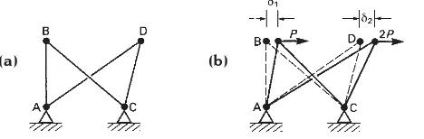
In Fig. A3.3 two independent statically determinate structures, ABC and ADC, are shown. They happen to share the same supports, A and C, but in every other respect they are independent. If horizontal loads of P
and 2Pare applied to joints B and D,
respectively, the structures will resist these;
The concept of statical
determinacy
Fig. A3.1 The framework (a) is statically determinate. Framework (b) is statically indeterminate because the four external reactions cannot be solved from the three equations of equilibrium which can be derived.
140
Fig. A3.2 Although the external force system of this structure is statically determinate the framework is statically indeterminate because it contains more elements than are required for internal stability. It will not be possible to solve the structure for all of the internal forces by considering static equilibrium only.
internal forces and reactions will be developed, all of which can be calculated from the
equations of equilibrium, and the elements will undergo axial strain, the magnitudes of which will depend on the elasticity of the material and the sizes of the element cross-sections. Both joints B and D will suffer lateral deflections but these will not affect the
internal forces in the elements, which will be solely dependent on the external loads and on the geometries of the arrangement (to a first approximation).
If a fifth element is added, which connects joints B and D, the system becomes statically indeterminate. The two joints are now
constrained to deflect by the same amount under all load conditions and if the two loads are applied as before the extent of the
resulting elongation or contraction of the elements will not be the same as occurred when the joints B and D were free to deflect independently. This means that the joint which previously deflected less will be pulled or pushed further than before and the reverse will occur to the other joint. A transfer of load will therefore occur along the element BD and this will alter the pattern of internal forces in the whole frame. The amount of load transfer, and therefore of change to the internal force system, will depend on the difference between the deflections which occurred to the two joints in the statically determinate forms. This is determined by the rigidity of the elements, so the distribution of internal forces in the
statically indeterminate structure is therefore dependent on the properties of the elements as well as on the overall geometry of the frame and the magnitudes of the external loads. The element properties must therefore be taken into account in the analysis of this structure. This is generally true of statically
indeterminate structures and is one of the important differences between statically determinate and statically indeterminate structures.
The fact that element properties have to be considered in the analysis of statically
indeterminate structures makes their analysis much more complicated than that of
equivalent statically determinate structures; in particular, it requires that the rigidity of the elements be taken into account. As this can only be done once the element dimensions have been decided and a material selected, it means that the design calculations for statically indeterminate structures must be carried out on a trial and error basis. A set of element sizes must be selected initially to allow the analysis to be carried out. Once the internal forces have been calculated the suitability of the trial sizes can be assessed by calculating the stress which will occur in them. The element sizes must normally be altered to suit the particular internal forces which occur and this causes a change in the pattern of the internal forces. A further analysis is then required to calculate the new internal forces,
followed by a further revision of the element 141
Fig. A3.3 The pattern of internal forces in a statically indeterminate structure depends on the properties of the elements as well as on the overall geometry of the arrangement. (a) ABC and ADC are independent statically determinate structures. (b) The two structures are free to deflect independently in response to load. (c) The
presence of element BD renders the arrangement statically
indeterminate. Joints B and D must undergo the same deflection; internal force, dependent on the relative magnitudes of S1andS2, occurs in BD and this alters the whole pattern of internal forces. The final distribution of internal force depends on the elasticity of the elements as well as the overall geometry of the structure.
dimensions. The sequence must be continued until satisfactory element sizes are obtained. Cycles of calculations of this type are routine in computer-aided design.
By comparison, the calculations for statically determinate structures are much more straightforward. The internal forces in the elements depend solely on the external loads and on the overall geometry of the structure. They can therefore be calculated before any decision on element dimensions or a structural material has been taken. Once the internal forces are known, a material can be chosen and appropriate element dimensions selected. These will not affect the pattern of the internal forces and so a single sequence of calculations is sufficient to complete the design.
A3.2.2 Efficiency in the use of material
The efficiency with which structural material is used is normally greater with statically
indeterminate structures because the presence of a larger number of constraints allows a more direct transmission of loads to the foundations and a more even sharing of load by all of the elements. The benefits of statical
indeterminacy in this respect are most easily
seen in relation to structures with rigid joints, in which the resulting structural continuity causes smaller bending moments to occur than are present in equivalent statically determinate structures under the same load conditions. As before the differences between the two types of structure can be appreciated by studying very simple examples.
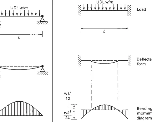
The simply supported beam (Fig. A3.4), whose supports offer no restraint against rotation of the beam ends, is a statically determinate structure. The deflected shape of this, in response to a uniformly distributed load, is a sagging curve in which, as in all structures which are subjected to bending, the intensity of the curvature at every cross-section is directly proportional to the magnitude of the bending moment at that cross-section. The curvature is greatest at mid-span and decreases to zero at the supports where the beam ends tilt but remain straight.
A beam whose ends are restrained against rotation is a statically indeterminate structure (Fig. A3.5). The fixed-end supports are each capable of producing three external reactions and the total of six reactions makes the solution of the external force system
142
Fig. A3.4 Load, deflection and bending moment diagrams for a statically determinate simply supported beam.
impossible from the three equations of equilibrium which can be derived. Another consequence of the end fixities, and of the moment reactions which result from them, is that the ends of the beam remain horizontal when a load is applied. The mid-span portion still adopts a sagging curve, but the amount of sag is less than in the simply supported case, because a reversal in the direction of the curvature occurs at each end. The effect is seen in the bending moment diagram, in which regions of negative bending moment occur to correspond with the hogging curvature at the beam ends. The reduction in the sag at mid-span is associated with a smaller positive bending moment than occurs in the simply supported beam.
The total depth of the bending moment diagram is the same for both beams, but the effect of the end fixity is to reduce the maximum positive bending moment at mid-span from wL/8, for the simply supported
beam, to wL/24 for the beam with fixed ends,
wherewis the total load carried and Lis the
span. The overall maximum bending moment in the fixed-ended beam is in fact a negative value of –wL/12, which occurs at its ends. The
effect of fixing the ends of the beam and of making it statically indeterminate is therefore to reduce the maximum value of the bending moment from wL/8 at mid-span to –wL/12 at
the supports.
As the bending stress in a beam is everywhere directly proportional to the bending moment, assuming that the cross-section is constant along its length, the
highest stresses in the fixed-ended beam occur at the ends of the span and are less, by a factor of 2/3, than the highest stress in the equivalent simply supported beam, which occurs at mid-span. The fixed-ended beam is therefore able to carry a load which is 1.5 times greater than the load on an equivalent simply supported beam before it is stressed to the same extent; it is therefore 1.5 times as strong. Conversely, a fixed-ended beam which is 2/3 the size of an equivalent simply supported beam can carry the same load with equal safety. The adoption of the statically indeterminate form therefore
allows a more efficient use to be made of the structural material. As with most gains, there is a cost, which in this case arises from the difficulty of providing fixed-ended support conditions.
In more complicated structures, where many elements are present, the benefits of end fixity are achieved by making the joints between them rigid. Such structures are called continuous structures and they are normally statically indeterminate. In the beam which is continuous over a number of supports (Fig. A3.6), the continuity between adjacent spans produces a deflected form which is a single continuous curve. The hogging at the supports corresponds to areas of negative bending moment and reduces the magnitude of the
143
Fig. A3.6 A beam which is continuous over a number of supports is a statically indeterminate structure. The magnitudes of the bending moments in each span are lower than if hinge joints were provided at each support (the statically determinate form).
Fig. A3.7 A frame with rigid beam-to-column joints is statically
positive bending moments in the mid-span positions. The effect of the hogging is therefore similar to that which is produced by the
moment reactions which occur in the fixed-ended beam of Fig. A3.5. The same effect is seen in the rigid frame (Fig. A3.7) in which the rigid beam-to-column joints allow the columns to restrain the ends of the single beam which is present.
A3.2.3 The ‘lack-of-fit’ problem
With the possible exception of in situreinforced
concrete structures, most structures are prefabricated to some extent so that their construction on site is a process of assembly. As prefabricated components can never be produced with precisely the correct
dimensions, the question of ‘lack-of-fit’ and of the tolerance which must be allowed for this is a necessary consideration in structural design. It can affect the decision on whether to use a statically determinate or indeterminate form, because the tolerance of statically determinate structures to ‘lack-of-fit’ is much greater than that of statically indeterminate structures. As in the case of other properties the reason for this can be seen from an examination of the behaviour of a small framework (Fig. A3.8).
The arrangement in Fig. A3.8(a) is statically determinate while that in Fig. A3.8(b) is an equivalent statically indeterminate form. It will be assumed that the frames are assembled from straight elements, that the structural
material is steel and that the hinge-type joints are made by bolting. The elements would be fabricated in a steel fabrication workshop and all bolt holes would be pre-drilled. However, it would be impossible to cut the elements to exactly the correct length, or to drill the bolt holes in exactly the correct positions; there would always be some small error no matter how much care was taken in the fabrication process.
The initial stages of the assembly would be the same for both forms and might consist of bolting the beams to the tops of the two columns. The resulting arrangements would still be mechanisms at this stage and any discrepancies which existed between the length of the next element to be inserted, that is the first diagonal element, and the length of the space into which it must fit, could be eliminated by swaying the assembly until the distance between the joints was exactly the same as the length of the element. The insertion of the first diagonal element would complete the assembly of the statically determinate form. To complete the statically indeterminate form the second diagonal must be added. If any discrepancy exists between the length of this and the distance between the joints to which it must be attached, the
distance cannot now be adjusted easily by moving the partly assembled frame because it is now a structure and will resist any force which is applied to it in an attempt to alter its shape. A significant force would therefore have to be applied to distort the frame before the final element could be inserted. This would produce stress in the elements, which would tend to restore the frame to its original shape when the force was released after the insertion of the final element. The presence of the second diagonal element in the frame would prevent it from returning to its original shape,
144
Fig. A3.8 The ‘lack-of-fit’ problem. (a) Statically determinate frame. (b) Statically indeterminate form. (c) The arrangement is unstable until the first diagonal element is inserted. There is no lack-of-fit problem in assembling the statically determinate frame. (d) After the first diagonal is in place the arrangement has a stable geometry. There is therefore a potential lack-of-fit problem in inserting the last element in the statically indeterminate version of the frame.
however, and the result would be that all of the elements in the frame would finally carry a permanent stress as a result of the ‘lack-of-fit’. This would be additional to any stress which they had to carry as a result of the application of the frame’s legitimate load.
The performance in respect of ‘lack-of-fit’ is an important difference between statically determinate and statically indeterminate structures. Statically determinate structures can be assembled fairly easily despite the fact that it is impossible to fabricate structural components with absolute accuracy as any discrepancy which exists between the actual dimensions of components and their intended dimensions can normally be accommodated during the construction process. This does, of course, result in a final structural geometry which is slightly different from the shape which was planned, but the level of accuracy reached in the fabrication is normally such that any discrepancy is undetectable to the naked eye despite being significant from the point of view of the introduction of ‘lack-of-fit’ stresses.
In the case of statically indeterminate structures even small discrepancies in the dimensions can lead to difficulties in assembly and the problem becomes more acute as the degree of indeterminacy is increased. It has two aspects: firstly, there is the difficulty of actually constructing the structure if the elements do not fit perfectly; and secondly, there is the possibility that ‘lack-of-fit’ stresses may be developed, which will reduce its carrying capacity. The problem is dealt with by minimising the amount of ‘lack-of-fit’ which occurs and also by devising means of
‘adjusting’ the lengths of the elements during construction (for example by use of packing plates). Both of these require that high standards are achieved in the detailed design of the structures, in the manufacture of its components and also in the setting out of the structure on site. A consequence of the ‘lack-of-fit’ problem, therefore, is that both the design and the construction of statically indeterminate structures are more difficult and therefore more expensive than those of
equivalent statically determinate structures.
A3.2.4 Thermal expansion and ‘temperature’ stresses
It was seen in Section A3.2.3 that in the case of statically indeterminate structures stresses can be introduced into the elements if they do not fit perfectly when the structure is assembled. Even if perfect fit were to be achieved initially, however, any subsequent alteration to the dimensions of elements due to thermal expansion or contraction would lead to the creation of stress. Such stress is known as ‘temperature’ stress. It does not occur in statically determinate structures, in which small changes in dimensions due to thermal expansion are accommodated by minor adjustments to the structure’s shape without the introduction of stress.
Thermal expansion must be considered in the design of most statically indeterminate structures and the elements made strong enough to resist the resulting additional stress which will occur. This depends on the range of temperature to which the structure will be exposed and on the coefficient of thermal expansion of the material. It is a factor which obviously reduces the load carrying capacity and therefore efficiency of statically
indeterminate structures.
A3.2.5 The effect of differential settlement of foundations
Just as a statically determinate structure can adjust its geometry in response to minor changes in the dimensions of elements
145
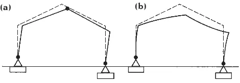
Fig. A3.9 The effect of differential settlement on determinate and indeterminate structures. (a) The statically determinate three-hinge frame can adjust its geometry to accommodate foundation movement without the introduction of bending in the elements. (b) Bending of elements and the introduction of stress is an inevitable consequence of foundation movement in the two-hinge frame which is statically indeterminate.
without the introduction of internal force and therefore stress, it can also accommodate differential settlement of its foundations (Fig. A3.9). Determinate structures can in fact tolerate fairly large foundation movements without distress to the structure. Statically indeterminate forms, on the other hand, cannot make this kind of adjustment without stress being introduced into the material, and it is therefore important that significant differential settlement of foundations be avoided in their case. The issue can affect the choice of structure type for a particular building. If, for example, a building is to be erected on a site where the ground conditions are problematic, such as might occur in an area liable to mining subsidence, the choice might be between a statically determinate structure on individual foundations which would be capable of accommodating movement or an indeterminate structure on deep piled or a raft foundation. The latter would probably be a considerably more expensive solution.
A3.2.6 The effect of the state of determinacy on the freedom of the designer to
manipulate the form
Because statically indeterminate structures contain more constraints than are required for stability, more than one path will normally exist by which a load can be conducted through the structure to the foundations. In other words, the task of conducting a load through the structure from the point at which it is applied to the foundations is shared between the various structural elements. This does not occur with statically determinate structures in which there is normally only one route by which a load can pass through the structure.
A consequence of the redundancy which is present in statically indeterminate forms is that elements can be removed without
compromising the viability of the structure (the remaining elements then carry higher internal forces). This property of statically
indeterminate structures gives the designer much more freedom to manipulate the form at the design stage than is available with a
statically determinate structure. In the case of a statically indeterminate two-way spanning reinforced concrete slab, for example, the designer has the freedom to incorporate voids in the floor slabs, cantilever the floors beyond the perimeter columns, and generally to adopt irregularity in the form which would not be possible with a statically determinate steel frame. The fact that statically indeterminate structures are self-bracing is another factor which increases the freedom available to the designer of the structure.
A3.3 Design considerations in
relation to statical determinacy
Most structural geometries can be produced in either a statically determinate or a statically indeterminate form depending on how the constituent elements are connected together. The question of which should be adopted in a particular case is one of the fundamental issues of the design process and the decision is influenced by the factors which have been considered above. The main advantage of statically indeterminate structures is that they allow a more efficient use of material than equivalent statically determinate forms. It is therefore possible to achieve longer spans and carry heavier loads than with statically
determinate equivalents. The principal disadvantage of statically indeterminate structures are that they are more complex to design and more difficult to construct than statically determinate equivalents; these factors usually make them more expensive despite their greater efficiency. Other
disadvantages are the possibilities of ‘lack-of-fit’ and ‘temperature’ stresses and the greater susceptibility of statically indeterminate structures to damage as a result of differential settlement of foundations. These various factors are weighed against each other by the designer of a structure who must decide which type is more suitable in an individual case.
The decision as to which material should be used for a structure is often related to the decision on determinacy. Reinforced concrete
is ideal for statically indeterminate structures due to the ease with which continuity can be achieved without the disadvantage of the ‘lack-of-fit’ problem and also to its low coefficient of thermal expansion, which results in
temperature stresses being low. Most reinforced concrete structures are therefore designed to be statically indeterminate.
The use of steel for statically indeterminate structures, on the other hand, can be
problematical due to the ‘lack-of-fit’ problem and to the relatively high coefficient of thermal expansion of the material. Steel therefore tends to be used for statically determinate structures rather than for statically
indeterminate structures unless the particular advantages of indeterminacy are specifically required in conjunction with the use of steel. Steel and timber are in fact particularly suitable for statically determinate structures due to the ease with which hinge-type joints can be produced in these materials.
Usually the circumstances of a particular building will dictate the choice of structure
type and material. If a building is of small or moderately large size with no very large spans then the simplicity of the statically
determinate form will normally favour its use. If very high structural efficiency is required to achieve long spans or simply to provide an elegant structural form then this might favour the use of statical indeterminacy in
conjunction with a strong material such as steel. The resulting structure would be expensive, however. Where relatively high efficiency is required to carry very heavy loads then a statically indeterminate structure in reinforced concrete might be the best choice. If a structure is to be placed on a site on which differential settlement is likely to occur, the use of a statically determinate form in conjunction with a suitable material such as timber or steel would probably be appropriate. The decision on the type of structure is
therefore taken in conjunction with the decision on structural material, and both are dependent on the individual circumstances of the building concerned.