GEOMETRIC PROCESSING WORKFLOW FOR VERTICAL AND OBLIQUE
HYPERSPECTRAL FRAME IMAGES COLLECTED USING UAV
L. Markelin a, *, E. Honkavaara a, R. Näsia, K. Nurminena, T. Hakalaa
a Finnish Geodetic Institute, P.O.Box 15 FI-02431 Masala, Finland- (lauri.markelin, eija.honkavaara, roope.nasi, kimmo.nurminen, teemu.hakala)@fgi.fi
Commission III
KEY WORDS: Structure-from-motion, Oblique, Hyperspectral, UAV, 3D point cloud
ABSTRACT:
Remote sensing based on unmanned airborne vehicles (UAVs) is a rapidly developing field of technology. UAVs enable accurate, flexible, low-cost and multiangular measurements of 3D geometric, radiometric, and temporal properties of land and vegetation using various sensors. In this paper we present a geometric processing chain for multiangular measurement system that is designed for measuring object directional reflectance characteristics in a wavelength range of 400-900 nm. The technique is based on a novel, lightweight spectral camera designed for UAV use. The multiangular measurement is conducted by collecting vertical and oblique area-format spectral images. End products of the geometric processing are image exterior orientations, 3D point clouds and digital surface models (DSM). This data is needed for the radiometric processing chain that produces reflectance image mosaics and multiangular bidirectional reflectance factor (BRF) observations. The geometric processing workflow consists of the following three steps: 1) determining approximate image orientations using Visual Structure from Motion (VisualSFM) software, 2) calculating improved orientations and sensor calibration using a method based on self-calibrating bundle block adjustment (standard photogrammetric software) (this step is optional), and finally 3) creating dense 3D point clouds and DSMs using Photogrammetric Surface Reconstruction from Imagery (SURE) software that is based on semi-global-matching algorithm and it is capable of providing a point density corresponding to the pixel size of the image. We have tested the geometric processing workflow over various targets, including test fields, agricultural fields, lakes and complex 3D structures like forests.
* Corresponding author. This is useful to know for communication with the appropriate person in cases with more than one author.
1. INTRODUCTION
Remote sensing based on unmanned airborne vehicles (UAVs) is a rapidly developing field of technology (Colomina and Molina, 2014). UAVs enable accurate, flexible, low-cost and multiangular measurements of 3D geometric, radiometric, and temporal properties of land and vegetation using various sensors. With light weight systems, typical flying altitudes are 10 m – 150 m and the areal extent ranges typically from few m2 to few km2. UAVs can be used in various environmental remote sensing tasks, such as precision agriculture or water quality monitoring. They also offer an interesting alternative to produce reflectance reference measurements for satellite sensor and image calibration and validation (cal/val). Several different UAV based spectrometric imaging techniques are already available, even for light-weight systems (Hruska et al., 2012; Zarco-Tejada et al., 2012; Buettner and Roeser 2014).
The main challenge with the UAV system related to the geometric orientation of the images is the limited payload that restricts the use of high-end GNSS/IMU systems. On the other hand, the use of GCPs for solving the exterior orientation of the images is laborious and often even impossible due to the restrictions of the target area. The positioning hardware have developed so that the location of the UAV can be recorded up to 0.5m accuracy at best. This would often be enough for the traditional photogrammetric systems, but also some information of the image rotations is still needed. The current IMU systems
do not yet provide the needed accuracy for the photogrammetric software systems. The emergence of sophisticated computer vision based algorithms such as structure-from-motion (SFM) (Wu, 2011) has opened new options for solving the exterior orientation of frame images collected with UAVs (Lisein et al., 203; Mancini et al., 2013; Mathews and Jensen, 2013). These methods do not require any preliminary information for solving the initial exterior orientation of the images in arbitrary coordinate system. The method is quite robust when dealing with UAV image blocks with large rotational differences and unknown orientations. Either image acquisition positions or some ground control points (GCPs) are needed for converting the solution to real world coordinates.
In this paper we present a geometric processing chain for multiangular measurement system that is designed for measuring object directional reflectance characteristics in a wavelength range of 400-900 nm (Honkavaara et al., 2014b). The technique is based on a novel, lightweight spectral camera designed for UAV use. The multiangular measurement is conducted by collecting vertical and oblique area-format spectral images. End products of the geometric processing are image exterior orientations, 3D point clouds and digital surface models (DSM). This data is needed for the radiometric processing chain that produces reflectance image mosaics and multiangular bidirectional reflectance factor (BRF) observations.
The whole spectral camera data processing workflow (with emphasis on the radiometric processing) has been developed in previous studies and presented in Honkavaara et al. 2012 and 2014b. The results of campaigns the over remote sensing test field has been presented in Honkavaara et al. 2014a and 2014b, over forests in Honkavaara et al. 2014a, over lakes in Honkavaara et al. 2013b and over agricultural fields in Honkavaara et al. 2013a and 2014a. This paper summarizes the geometric processing part of the spectral camera image processing workflow and especially the initial geometric orientation using structure-from-motion algorithm.
The Fabry-Perot Interferometer (FPI) spectral camera is used to provide spectral reflectance data. When the FPI is placed in front of the sensor, the spectral sensitivity of each pixel is a function of the interferometer air gap. Each spectral band is obtained with a small time delay when using different air gap values, thus each band has a slightly different position and orientation. With an FPI spectral camera, it is possible to collect spectral data cubes with an area image format. When using overlapping area format images, it is possible to obtain stereoscopic and multiangular views of objects.
The geometric processing workflow consists of the following three steps: 1) determining approximate image orientations using Visual Structure from Motion (VisualSFM) software (Wu 2011; Wu et al., 2013), 2) calculating improved orientations and sensor calibration using a method based on self-calibrating bundle block adjustment (standard photogrammetric software) (this step is optional), and finally 3) creating dense 3D point clouds and DSMs using Photogrammetric Surface Reconstruction from Imagery (SURE) software (Rothermel et al. 2012) that is based on semi-global-matching algorithm and it is capable of providing a point density corresponding to the pixel size of the that is based on semi-global-matching algorithm and it is capable of providing a point density corresponding to the pixel size of the image.
There are two aspects that make the current imaging system different compared to photogrammetric UAV imaging systems equipped with conventional consumer frame cameras. First, each band of one data cube has a slightly different position and orientation, and the system GPS records position only for the discussed in section 4 and conclusions are given in section 5.
2. MATERIALS 2.1 Spectral camera
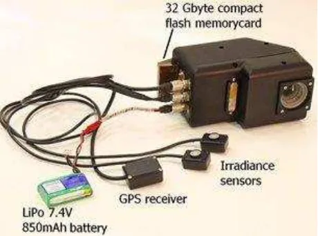
The predominant instrument used for UAV reflectance measurements is the Fabry-Perot Interferometer-based (FPI) spectrometric camera (Figure 1), developed by the VTT Technology Research Center in Finland (Saari et al. 2013). This technology provides area-format spectral data cubes, but each band in the data cube has a slightly different position and orientation because they are exposed sequentially. The FPI spectral camera can operate in the wavelength range of 400-1000 nm, with a full width at half maximum (FWHM) of 10-40
nm; the number of bands (up to 40) and their characteristics can be selected flexibly according to the requirements of the application. The weight of the spectral camera (prototype 2012b) is 700g and has a focal length of 11 mm, an image size
of 648 x 1024 pixels and a pixel size of 11 μm.
Furthermore, the technology allows for stereoscopic and multi-ray views of objects when overlapping images are used, and an even larger range of observation angles can be obtained by using oblique views. For the FPI camera images, the FOV is <± 16° in the flight direction, < ± 27° in the cross-flight direction,
and < ± 31° the format corner. We tilted the camera’s optical
axis around the axis perpendicular to the flight direction (the roll axis) using an oblique angle of 25°–30°. This provided maximum viewing angles of approximately 40° in the flight direction when the border areas of the images are not used.
The camera includes a standard GPS receiver, and the XY-location and precise starting time of the data cube recording is saved for each data cube.
The interior orientation of the spectral camera has been solved using an iWitness software, and the orientation has been updated for each campaign using self-calibration during the bundle block adjustment, if possible.
Figure 1. The FPI spectral camera.
2.2 UAV and other payload
We used an eight-rotor UAV, which was based on MikroKopter autopilot and Droidworx AD-8 extended frame having a 1.5 kg payload (Figure 2). The UAV was equipped with a stabilized camera mount, the AV130 (Photo-Higher, New Zealand), which compensates for tilts and vibrations around the roll and pitch directions. The autopilot saves the flight path of the UAV multiple times per second; the XY-position is based on the GPS and height on barometric pressure. The UAV can also be equipped with various supplementary off-the-self positioning and IMU sensors. With proper post-processing, it is possible to achieve a positioning accuracy up to 0.5 m with very small and light weight sensors.
Figure 2. Mikrokopter UAV with the spectral camera.
2.3 Campaigns
The Finnish Geodetic Institute (FGI) has used different versions of the FPI spectral camera in various campaigns during the years 2010-2014. The target areas have included photogrammetric test fields, agricultural fields, forests, lakes and swamps. The geometric processing workflow for each campaign has varied slightly depending on the target, used sensors and imaging conditions. Some areas allow installing GCPs over the target area whereas on other areas such as lakes or dense forests we have to rely on direct georeferencing.
The flying height in different campaigns varies between 40 and 150 meters, providing ground sampling distances of 4cm and 15cm respectively for the FPI spectral camera.
The spectral camera data processing workflow has been tested most thoroughly at the Sjökulla remote sensing test field (Honkavaara et al. 2014b). There we have tested both nadir and oblique image blocks and the test field is equipped with precise geometric ground control points (GCPs). The test field is practically flat and covered with various gravel targets.
Agricultural fields (Honkavaara et al. 2013a, 2014a) and lakes (Honkavaara et al. 2013b) have been imaged using nadir configuration. Agricultural fields are more or less homogenous targets with varying 3D structure. Lakes and waters in general are totally flat, mostly homogenous and featureless targets.
Forest (Honkavaara et al., 2014a) target has been imaged using both nadir and oblique configurations. Forests have highly three dimensional structure and depending on the forest type, it may have various levels on homogeneity/inhomogeneity. Figure 3 shows an example of an oblique image captured over a homogenous scots pine forest.
Figure 3. Example of oblique image captured with the spectral camera. One channel image.
3. METHODS
Due to the operating principle of the FPI spectral camera, the exterior orientation of each band of one data cube has to be solved separately. The sensor records the exact time of the start of the data cube recording, and the time difference between the first and other channels is stored to image meta data.
3.1 Initial exterior orientation using SfM
The initial geometric orientation of the FPI image is solved using the Visual Structure from Motion (VisualSFM) software (Wu, 2011; Wu et al. 2013). Images are converted to 8bit per pixel grayscale jpeg-images that are suitable for the software.
The most accurate solution would be to solve the exterior orientation of each band of each data cube separately, but due to computational efficiency, we normally put three different bands to VisualSFM calculation (Figure 4). Then the orientations of the other bands are interpolated based on the flight trajectory of the reference bands using the known time difference between the bands.
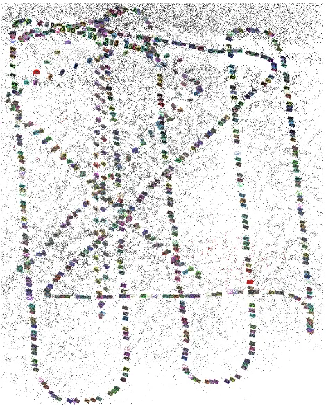
In the simplest case the VisualSFM workflow can be described as follows. First the images are loaded to the software. Next step is to calculate image features and feature matches between images. Then the actual exterior orientation solving, or sparse reconstruction, is started. These steps require minimal user interaction. Only the sensor interior orientation parameters are given, if known. The calculation provides the sparse reconstruction of the target area with the camera orientations. Example of one solution is given in Figure 6.
Finally, the VisualSFM orientations are converted into the desired object coordinate system either by using information on the flight trajectory measured using GPS or by using GCPs. The transformation is only affine transformation of the whole solution to the desired coordinate system so it does not affect to the overall accuracy of the solution or relations between different images.
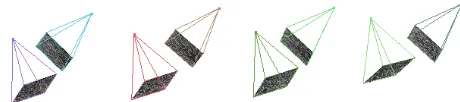
Oblique images are not a problem for VisualSFM, as it is developed mainly terrestrial application in mind. Example of using oblique images with VisualSFM is shown in Figure 5.
Figure 4. Example of three sequential spectral camera data cubes with three bands each. Time difference between the channels are 0s, 1.125s and 1.6s.
Figure 5. Example of oblique image exterior orientations from two flight lines.
3.2 Orientation improvement
As the image features used as tie points between different images in VisualSFM provide only pixel level accuracy, the final accuracy of the whole solution is not of the highest level. If a higher geometric accuracy is desired, the exterior orientations from VisualSFM can be imported to any standard photogrammetric system. Also, if the accuracy of these initial orientations is not sufficient and/or the complexity of the object (e.g. forest) prevents the automatic tie point extraction to work, the tie points for the VisualSFM solution can be imported to the photogrammetric software. We have used BAE Systems Socet Set and Socet GXP in our calculations.
Figure 6. VisualSfM exterior orientation solution for combined oblique and nadir image block collected over forest. One channel from the data cube was used for oblique block and three channels for the nadir block.
3.3 Dense 3D point cloud creation
Digital surface model (DSM) of the target area is needed for acquiring directional reflectance data of the object. Currently we use Photogrammetric Surface Reconstruction from Imagery (SURE) software (Rothermel et al. 2012) that is based on semi-global-matching algorithm and it is capable of providing a point density corresponding to the pixel size of the image. The exterior orientations from VisualSFM can be imported directly to SURE. If orientations from Socet GXP are used, the orientations have to be converted to proper format. The end products of the SURE calculations are dense 3D point clouds for each image. These point clouds can then be combined to create DSM. Example of one DSM based on the spectral camera is shown in Figure 7.
Figure 7. DSM of a forest area created with SURE, 10cm point interval.
4. RESULTS AND DISCUSSION
The FPI spectral camera has been used in multiple UAV campaigns over various target areas (Honkavaara et al. 2013a, 2013b, 2014a, 2014b). The geometric processing workflow has changed from campaign to campaign based on available positioning data, GCPs and difficulty of the target. The VisualSFM –based method was found to work successfully over targets that provide enough texture for feature detection to work i.e. on all other targets except plain water. The processing power and time can restrict the number of images used in the SFM and SGM –based methods. However, with a modern desktop computer and up-to-date graphics card, the processing of more than 1000 FPI images is possible in couple of hours.
The accuracy of the presented geometric processing method was evaluated over the Sjökulla test field. The flying height of the test block was 40m and the GSD of the FPI images was 4cm. After making the block adjustment with Socet Set, the root-mean-square error (RMSE) of residuals for the GCPs was 5.9 cm, 4.6 cm, and 7.3 cm for the FPI images at the X, Y, and Z coordinates. (Honkavaara et al. 2014b)
Forest target (Honkavaara et al. 2014a) seemed to be difficult for VisualSFM, when using only one band per data cube. The solution was found only for the oblique image block. When adding two other bands to the (totally three bands) solution was also found for the nadir image block (Figure 6). However, the self-calibrating bundle block adjustment using the Socet Set was not successful in forest; it is likely that the tie point measurement strategy of the software could not tolerate the great differences in perspective due to the 3D forest object, low flying altitude and relatively wide camera angle. The forest DSM (Figure 7) was calculated based on the VisualSFM solution only.
The most difficult target for the presented geometric processing workflow was water (Honkavaara et al. 2013b). This is because water is homogenous and featureless, meaning that feature detection methods cannot find enough features and the image matching fails. Best solution would be to have accurate enough direct georeferencing, but current GPS/IMU systems used with small UAVs needs some further development. One rather laborious approach would to fly only straight lines over water and perform turns over land if possible. In this case SFM-based methods would get the exterior orientation solutions for the images in turns, and then the orientations of the images over water could be interpolated from them. The advantage of using UAVs over water areas is that there is a better possibility for adjusting the flight speed, which was essential for the camera that was used. Waters are dark targets and require a long exposure times.
If the VisualSFM does not find the solution for the given image block, there is not much to do. The only solution would be to add more images to provide better image overlap between images. With the FPI sensor, we could add additional bands, but this helps only in the flying direction. So it is crucial to plan UAV campaigns with as high forward and side image overlap as possible, and also use oblique viewing angles if it is possible.
A further improvement will involve utilizing high-quality GPS information to support the georeferencing process. The accurate object geometric model and georeferencing information could also enable more detailed object characterization, up to the level of a decimetre in a forest area and even better over more simple targets. Also the accuracy and stability of the interior orientation parameters of the FPI spectral camera needs further studies. orientation. In the future we will analyse the geometric accuracy of the point clouds more thoroughly.
5. CONCLUSIONS
The VisualSFM –based method was found to work successfully over various targets, and the special characteristics of the FPI spectral imaging system (time difference between bands and oblique viewing angles) turned out to strengthen the solution due to improved image overlap. The good block geometry with vertical and oblique images provided good accuracy and the photogrammetric DSM generated by SURE using FPI spectral camera images was of high quality. Our results proved that the proposed measurement system was capable of measuring the 3D geometric and spectral characteristics of a complex object automatically. Based on the results, we expect that full automation can be obtained in 3D geometric structure measurement when using (1) a pre-programmed UAV flight trajectory and autopilot to take care of the flight, (2) GPS trajectory information and the structure from motion method to determine image orientations, (3) automatic dense image matching to measure a detailed 3D geometric object model. Further improvements in the geometric accuracy and reliability are expected when using more accurate GNSS trajectory information and emphasising the geometric system calibration.
ACKNOWLEDGEMENTS
We are grateful to the European Metrology Research Program (EMRP) for funding the project. The EMRP is jointly funded by the EMRP participating countries that are part of the European Association of National Metrology Institutes and the European Union. This project is part of a Researcher Excellence Grant project, which in turn falls under the EMRP project
“Metrology for Earth Observation and Climate”. We
acknowledge the Metrology Research Institute at Aalto University for their support in providing reflectance standard for our investigation. Journal of Photogrammetry and Remote Sensing 92(2014) 79-97.
Honkavaara, E., Hakala, T., Saari, H., Markelin, L., Mäkynen, J., Rosnell, T., 2012: A process for radiometric correction of UAV image blocks. – PFG – Photogrammetrie, Fernerkundung, Geoinformation 2012 (2): 115–127.
Honkavaara, E., Saari, H., Kaivosoja, J., Pölönen, I., Hakala, T., Litkey, P., Mäkynen, J., Pesonen, L., 2013a: Processing and Assessment of Spectrometric, Stereoscopic Imagery Collected Using a Lightweight UAV Spectral Camera for Precision Agriculture. – Remote Sensing 5 (10): 5006–5039.
Honkavaara, E., Hakala, T., Kirjasniemi, J., Lindfors, A., Mäkynen, J., Nurminen, K., Ruokokoski, P., Saari, H., Markelin, L., 2013b. New light-weight stereoscopic spectrometric airborne imaging technology for high-resolution environmental remote sensing – case studies in water quality mapping. International Archives of the Photogrammetry, Remote Sensing and Spatial Information Sciences, Volume XL-1/W1, ISPRS Hannover Workshop 2013, 21 – 24 May 2013, Hannover, Germany
Honkavaara, E., Markelin, L., Hakala, T., Peltoniemi, J., 2014a. Metrology of image processing in spectral reflectance measurement by UAV: The international archives of the photogrammetry, remote sensing and spatial information sciences, Vol XL-3/W1. EuroCOW 2014, the European Calibration and Orientation Workshop, 12-14 February 2014, Castelldefels, Spain.
Honkavaara, E., Markelin, L., Hakala, T., Peltoniemi, J., 2014b. The metrology of directional, spectral, reflectance factor measurements based on area format imaging by UAVs. Photogrammetrie - Fernerkundung – Geoinformation 3/2014, pp. 0175-0188.
Hruska, R., Mitchell, J., Anderson, M., Glenn N.F., 2012. Radiometric and geometric analysis of hyperspectral imagery acquired from an unmanned aerial vehicle. Remote Sensing 4 (9): 2736–2752.
Lisein, J., Pierrot-Deseilligny, M., Bonnet, S., Lejeune, P., 2013. A photogrammetric workflow for the creation of a forest canopy height model from small unmanned aerial system imagery. Forests 2013, 4, 922-944.
Mancini, F., Dubbini, M., Gattelli, M., Stecchi, F., Fabbri, S., Gabbianelli, G., 2013. Using unmanned aerial vehicles (UAV) for high-resolution reconstruction of topography: the structure from motion approach on coastal environments. Remote Sensing 2013, 5, 6880-6898.
Mathews, A.J. and Jensen, J.L.R, 2013. Visualizing and quantifying vineyard canopy LAI using an unmanned aerial vehicle (UAV) collected high density structure from motion point cloud. Remote Sensing 2013, 5, 2164-2183.
Rothermel, M., Wenzel, K., Fritsch, D., Haala, N., 2012. SURE: Photogrammetric Surface Reconstruction from Imagery. Proceedings LC3D Workshop, Berlin , December 2012
Saari, H., Pölönen, I., Salo, H., Honkavaara, E., Hakala, T., Holmlund, C., Mäkynen, J., Mannila, R., Antila, T., Akujärvi, A., 2013. Miniaturized hyperspectral imager calibration and UAV flight campaigns, Proc. SPIE 8889, Sensors, Systems, and Next-Generation Satellites XVII, 88891O (October 24, 2013); doi:10.1117/12.2028972
Wu, C., Agarwal, S., Curless, B., Seitz, S.M., 2011. Multicore Bundle Adjustment, CVPR 2011.
Wu, C., 2013. Towards Linear-time Incremental Structure From Motion, 3DV 2013.
Zarco-Tejada, P.J., Gonzalez-Dugo, V., Berni, J.A.J., 2012. Fluorescence, temperature and narrow-band indices acquired from a UAV platform for water stress using a micro-hyperspectral images and a thermal camera. – Remote Sensing of Environment 117: 322–337