IMPLEMENTATION OF A REAL-TIME STACKING ALGORITHM IN A
PHOTOGRAMMETRIC DIGITAL CAMERA FOR UAVS
Ahmad Audia,b, Marc Pierrot-Deseillignya,c, Christophe Meynarda, Christian Thoma
a
IGN, LaSTIG, LOEMI, 73 Avenue de Paris, 94160 Saint-Mand´e, France - [email protected] b
Universit´e Paris-Est, 6-8 Avenue Blaise Pascal, 77420 Champs-sur-Marne, France - [email protected] cENSG, 6-8 Avenue Blaise Pascal, 77420 Champs-sur-Marne, France - [email protected]
KEY WORDS:UAVs, image stacking, real-time, hardware/Software co-design, FPGA, image processing.
ABSTRACT:
In the recent years, unmanned aerial vehicles (UAVs) have become an interesting tool in aerial photography and photogrammetry activities. In this context, some applications (like cloudy sky surveys, narrow-spectral imagery and night-vision imagery) need a long-exposure time where one of the main problems is the motion blur caused by the erratic camera movements during image acquisition. This paper describes an automatic real-time stacking algorithm which produces a high photogrammetric quality final composite image with an equivalent long-exposure time using several images acquired with short-exposure times.
Our method is inspired by feature-based image registration technique. The algorithm is implemented on the light-weight IGN camera, which has an IMU sensor and a SoC/FPGA. To obtain the correct parameters for the resampling of images, the presented method accurately estimates the geometrical relation between the first and theNthimage, taking into account the internal parameters and the distortion of the camera. Features are detected in the first image by the FAST detector, than homologous points on other images are obtained by template matching aided by the IMU sensors. The SoC/FPGA in the camera is used to speed up time-consuming parts of the algorithm such as features detection and images resampling in order to achieve a real-time performance as we want to write only the resulting final image to save bandwidth on the storage device. The paper includes a detailed description of the implemented algorithm, resource usage summary, resulting processing time, resulting images, as well as block diagrams of the described architecture. The resulting stacked image obtained on real surveys doesn’t seem visually impaired. Timing results demonstrate that our algorithm can be used in real-time since its processing time is less than the writing time of an image in the storage device. An interesting by-product of this algorithm is the 3D rotation estimated by a photogrammetric method between poses, which can be used to recalibrate in real-time the gyrometers of the IMU.
1. INTRODUCTION
In the last decades, the civil use of unmanned aerial vehicles (UAVs) has grown exponentially, this led the LOEMI team of IGN/LaSTIG (Institut National de l’Information G´eographique et Foresti`ere) to design an ultra-light digital camera (Martin et al., 2014) better adapted for exploiting photogrammetry and metrol-ogy applications than consumer cameras when using UAVs (Daakir et al., 2016), (Tournadre et al., 2015). This SoC/FPGA-based camera will make possible to implement in hardware some real-time image processing algorithms. Night-real-time surveys and nar-row spectral bandwith imagery are one of the next applications targeted by IGN, this type of applications needs a long-exposure time imagery that usually exhibits a motion blur due to erratic movements of the UAV. This paper presents a stacking algorithm that can provide in real-time an accurate blur-free composite im-age with an equivalent long exposure where only the resulting image will have to be saved in order to ensure a better overall frame rate. The main part of this algorithm is feature-based im-age registration (Le Moigne et al., 2010) that consists of features detection in the first image, features matching in all other images, geometrical transformation estimation (Estimation of the map-ping function parameters) between all images, and resampling of the images. This paper is based on an article submitted to the Sensors journal. Actually, the UAV is submitted to rotation or translation movements in the 3D-space. So to take into account the perspective effects, our problematic needs to have the DSM (Digital Surface Model). Unfortunately, this treatment is not pos-sible in real-time until now. In absence of the DSM, we study two
particular approaches in our work:
• the first approach considers that the drone is quasi-stationary.
In this situation, the optical center of the camera is fixed, which leads to take only into account only the orientation of the camera and therefore only the deformation due to 3D rotation is corrected.
• the second approach considers that the drone undergoes a
2D translation in addition to the 3D rotation. In this sit-uation, we use the 2D planar homography as geometrical transformation between images which leads to correct re-sults when the scene can be considered as planar.
Some tests have been achieved on a Copter 1B UAV from Wikhy-dro equipped with the IGN camera to assess accuracy of the method and some of the results are presented.
2. HARDWARE
Figure 1.IGN lightweight photgrammetric camera
6 axis IMU
CMV20000-CMOS Sensor (20 MP) "SoC- FPGA Zynq 7030" chip
Figure 2. The CMOS Sensor with the inertial sensors and the embedded intelligence (SoC/FPGA).
calibrated (standard radial distortion model) before surveys using MicMac, the free open-source photogrammetric software devel-oped at IGN (Pierrot Deseilligny and Clery, 2011).
3. IMAGE AND DATA PROCESSING
Figure 3. Architecture of the algorithm (hardware/software co-design).
This algorithm is implemented and executed in the camera. At first, it was developed on a desktop PC. The architecture of the algorithm is illustrated in Figure 3.
3.1 FEATURES DETECTION
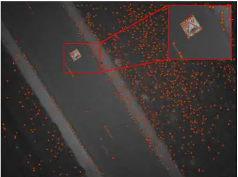
In our work, the choice of the feature detection algorithm was dictated essentially by its ability to find in a single image a rea-sonable number of good features and by its simplicity. After an-alyzing main existing feature detectors (Pena, 2012) (Le and Gonzalez, 2009), we selected the FAST (features from acceler-ated segment test) detector algorithm developed by (Rosten and Drummond, 2005). We added a simple grid-adapted features se-lection consisting of partitioning the image into blocks and keep-ing only in each block the first feature found by the detector, thus achieving a more uniform distribution of features as shown in Figure 6. A hardware implementation of the FAST detector has been done by (Kraft et al., 2008), that are more complex and uses more resources in their design. The global design presented
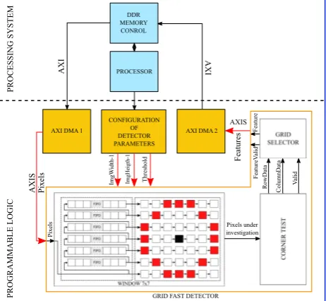
Figure 4.The global design of the grid fast detector implementa-tion.
in Figure 4 was implemented and tested on the Xilinx/Zynq of the camera. Our solution uses the standard DDR RAM memory for storing both images and coordinates of features. The AXI bus was used to connect the processor system and memory. The AXIS transports the data stream between modules in master/slave modes. Table 1 illustrates the resources used in FPGA for the im-plemented design.
Resource Used Available %
Slice LUTs 232 78600 0.30
Slice of 4 registers 472 157200 0.30
Memory (blocks of 36 KB) 6 265 2.26
Clocking 1 32 3.13
Table 1. Resources usage of the FAST detector design in Xilinx/Zynq-7030 FPGA.
3.2 FEATURES MATCHING
the grid selector and that the size of the search areas is small (11
×11 pixels) due to IMU prediction. We benefit from the
pres-ence of two cores on the camera to accelerate this part in software using the OpenMP library.
First image Nthimage
imu
Figure 5. Successive steps to obtain the coordinates of corre-sponding location of pixel in other image. Rn
imuis the 3D
rota-tion obtained by IMU between the first image and theNthimage.
Figure 6.Features detected by FAST algorithm in the first image. The threshold choosen here is 15. The number of blocks of grid is fixed to10×10. The resolution of image is2560×1920pixels.
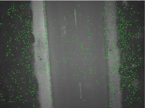
Figure 7. Search areas obtained by the gyrometers of IMU be-tween the first image and the10th
image. The green points repre-sent the homologous points obtained by template matching. The size of each search area is11×11pixels. The resolution of image
is2560×1920pixels.M×N= 60×60. Threshold = 8
3.3 ESTIMATION OF GEOMETRICAL TRANSFORMA-TION BETWEEN IMAGES
After having good homologous pairs between images, we need to estimate optimally the geometrical relation that permits to map pixel coordinates from one image to another. Two geometrical transformations can be used here, the 3D rotation between poses and the 2D homography between images. The choice of one of
these transformations depends on the real movement of the cam-era as explained in the introduction. The estimation is established by least squares method. In this context, outliers are eliminated automatically to improve the robustness. This part has already in software a real-time performance.
3.4 GEOMETRICAL TRANSFORMATION USED FOR RE-SAMPLING
For the resampling, we use either the 3D rotation or the 2D ho-mography. RMS errors produced by the least squares estimation serve as a quality factor to choose one of them. The internal ori-entation parameters (in our case: the coordinates of the centre of projection of the image, the focal length of the lens, the coordi-nates of the center of distortion, the radial lens distortion polyno-mial coefficients) produced by the optical calibration process and the estimated geometrical transformation permit to map all pixel coordinates from the first image to others: let us consider that
First image Nthimage
img
Figure 8. Successive steps to obtain the coordinates of corre-sponding location of pixel in other image.Rn
imgis the estimated
3D rotation between the first image and theNthimage.
Figure 9. Successive steps to obtain the coordinates of corre-sponding location of pixel in other image.Himgn is the estimated
2D homography between the first image and theNth
image.
Pi1(u, v)is a 2D point in the plan of the first image. First, the
geometric distortion is removed, thenP1
i(u, v)is transformed to
a 3D vector
−→
Vi1(x, y, z) in the camera coordinates system, the
origin of this system is at the optical center of the camera. Af-ter applying the inverse of the 3D rotation (Rn) to−V→1
i(x, y, z),
we obtain a new vector−V→in(x′, y′, z′)that will be projected into
the plan of theNth
image to have the corresponding 2D point
Pin(u′, v′)after applying again the geometric distortion.
3.5 NON-ACCELERATED IMAGE TRANSFORMATION AND RESAMPLING SOLUTION
The geometrical transformation is applied on each pixel of the first image to obtain the location of corresponding point on other images. Then, we use bilinear interpolation to find the resampled value of each pixel on other images. Removing and applying distortion is the most computation intensive task in the geomet-rical transformation process. Timing results presented in Table 3 demonstrate that this phase is still an important part of the timing budget, so we should accelerate it using a new approach.
3.6 ACCELERATION IN SOFTWARE OF THE RESAM-PLING
K×Lblocks, and on computing the precise mapping of the only
corners of each block for all other images, then other pixels in-side each block can be computed using the bilinear interpolation. Thus avoiding a lot of multiplications. To accelerate the
find-P
First image N imageth
Rnimg
Figure 10. The accelerated approach of image transformation and resampling.Tn
img=Rnimgis the geometrical transformation
between the first image and theNthimage. p1,p2,p3,p4, are the corners of the first block of the first image. p1′,p2′,p3′,p4′ are the projected points in theNth
image. K×Lis configured
so that the shape of the block is always a square.
ing of the resampled value of each pixel on other images, we use the nearest neighbor interpolation instead of the bilinear interpo-lation. Results demonstrate that the quality of stacking image doesnt’ show a major loss of accuracy as shown in Figure 21. In terms of computing, this approach provides a near real-time performance as shown in Table 3. Consequently, it should be im-plemented in the FPGA to obtain a real-time performance.
3.7 IMPLEMENTATION IN HARDWARE OF THE AC-CELERATED SOFTWARE RESAMPLING
To benefit maximally from the presence of the SoC in the camera, one of the two cores calculates the location of the four projected points for the next block in all images using the preceise map-ping, the second one calculates the parameters of the “y” parts of the next line inside the block. During that time, the IP core in the programmable logic part calculates the “x” part of the bilin-ear function, process the stacked line and than writes the stacked line on the appropriate position in the memory. Since the rota-tion between images is considered as small, there is a big chance that projected points are located one after another on the same line. For this reason, we use a cache of 8 bytes in order to reduce the access to memory. We use theV ivadoHLSsoftware from Xilinx to design our algorithm by compiling the adapted C/C++ code into logic elements. Table 2. illustrates the resources used
Resource Used Available %
Slice LUTs 1742 78600 2.21
Slice of 4 registers 2400 157200 1.52 Memory
(blocks of 36 KB) 2.5 265 0.94
DSPs 1 400 0.25
Table 2. Resources usage of the resampling design in Xilinx/Zynq-7030 FPGA.
in the FPGA for the resampling part. Our design uses little FPGA resources, that allows to duplicate it to accelerate the processing.
4. RESULTS AND DISCUSSION 4.1 TEST SURVEYS
We performed some experiments to quantify the accuracy and performance of our accelerated resampling method. We used the hardware previously described in “hardware” section. Several datasets have been acquired by the IGN camera. Each dataset consists in sequence of ten images acquired at the maximum frame rate of the CMOS (30 images/s).
For this first test, the camera prototype we used was fitted with a Bayer sensor and has a resolution of20MP(5120×3840).
Our work aims to be used for a narrow spectral imaging system consisting of several monochrome IGN cameras, thus we use the
5MP(2560×1920)grayscale images obtained from the original
pixel-stream by averaging each green pair of the Bayer pattern. The Copter 1B UAV from Wikhydro used for surveys is shown in Figure 11
Figure 11.UAV type Copter 1B developed by Wikhydro. Source : (Website wikhydro)
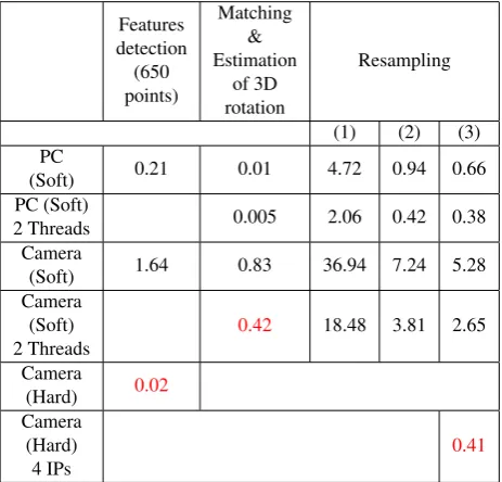
4.2 TIMING RESULTS (IN SECONDS)
Features
(Soft) 0.21 0.01 4.72 0.94 0.66
PC (Soft)
2 Threads 0.005 2.06 0.42 0.38
Camera
(Soft) 1.64 0.83 36.94 7.24 5.28
Camera
Table 3. (1): geometrical transformation using the 3D rotation and bilinear interpolation, (2): Accelerated geometrical trans-formation with bilinear function method and bilinear interpola-tion, (3): Accelerated geometrical transformation with bilinear function method and Nearest-neighbor interpolation
Table 3 shows that for software versions, the factor gain in time is 5 between (1) and (2) and 7 between (1) and (3). This factor be-comes 8 between the initial software version(1) and the hardware version. Benefiting from the presence of dual-core processors in the camera, we use the OpenMP library to accelerate the algo-rithm, the number of threads is set to 2, the time of processing of this part is reduced by half. Our method achieve a real-time per-formance in comparison to the time needed for writing an image in the SD-Card storage. The IP duplication is used to process in
0.2 0.4 0.6 0.8 1 1.2 1.4 1.6 1.8 2
1 2 3 4 5 6 7 8
Time (s)
Number of IPs
Non cache - SizeCell 80 x 80 Non cache - SizeCell 160 x 160 Non cache - SizeCell 320 x 320 SizeCell 80 x 80 SizeCell 160 x 160 SizeCell 320 x 320
Figure 12.Time of resampling part in function of number of hard-ware IPs used.
parallel several lines of each block. (Figure 12) shows the effect of the impact of the number used IPs with respect to the size of the cells of the grid and the use of the eight pixels input cache. So we choose to use 8 IPs in the following tests, thus gaining a factor of 5 in computing time.
4.3 QUALITY OF THE ORIGINAL STACKED IMAGE
Figure 13. The stacked image. The red part is the non-commun part between the first image and the10th
image.
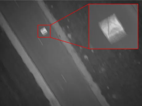
Figure 13 demonstrates visually that no motion blur affect the stacked image. By comparing the stacked image with the average image as shown in Figure 14, we can constate that our method can be used to eliminate the motion blur caused by erratic move-ment of the camera.
To qualify more precisely the quality of the stacked image, we calculate respectively the radiometric profile of the same line of both the stacked image and the first image. Figure 15 presents that the two profiles are very close each to other. The radiometric profile of the stacked image is more smooth due to the geometri-cal interpolation.
Figure 14. This image is obtained by the average of the ten im-ages. The angular motion between images is 0.9 degree corre-sponding to 44 pixels.
20 30 40 50 60 70 80 90 100 110
0 500 1000 1500 2000 2500 3000
Radiometric value
x
(1) (2)
Figure 15. Radiometric profil of the first image (red) and the stacked image (green).
4.4 CASE OF NON-PURE CAMERA ROTATION MOVE-MENT
Figure 16 and Figure 17 illustrate a case where the UAV has suffered a X-translation movement. Here, the rotation estimated
Figure 16. Residus obtained by the 3D rotation estimation be-tween the first image and the10thimage.
expected. This residual movement, which is not compensated for by the rotation, can be absorbed by 2D homography, and Figure
Figure 17. Residus obtained by the 2D homography estimation between the first image and the10th
image.
17 demonstrates that the residual errors in the estimated homog-raphy are constant over images and much lower than those for the estimated 3D rotation. This translation movement has been proved by calculating the external orientation of the camera dur-ing each acquisition (with MicMac software).
4.5 QUALITY OF THE STACKED IMAGE OBTAINED BY THE ACCELERATED METHOD
Figure 18 and Figure 19 demonstrate that the difference (in pix-els) according to the two axis of image between the projected point obtained by the precise mapping and the projected point obtained by the bilinear function is continued especially across the borders of blocks in the image.
Figure 18.Difference (in pixels) according to x axis for each pixel between the projected point obtained by the precise mapping and the projected point obtained by the bilinear function between the
1st
and the10th
image :Dif fmax= 0.0146.
Additionally, the maximum distances (in pixels) between points projected by the precise mapping and points projected by the bilinear function doesn’t exceed the 3 hundredths as shown in Figure 20. From the two stacked images obtained using the two accelerated methods, the two radiometric profiles present a very similar content as presented in Figure 21 that means that the ac-celerated method doesn’t affect the quality of the stacked image.
Figure 19.Difference (in pixels) according to y axis of image for each pixel between the projected point obtained by the precise mapping and the projected point obtained by the bilinear function between the 1stand the 10thimage :Dif fmax= 0.0162.
Figure 20. Maximum distance (in pixels) between the point pro-jected by the precise mapping and the point propro-jected by the bi-linear function in each block of the grid of the image.
20 30 40 50 60 70 80 90 100 110
0 500 1000 1500 2000 2500 3000
Radiometric value
x
(1) (2)
Figure 21. Radiometric profile for : (1) the stacked image ob-tained by accelerated transformation and bilinear interpolation, (2) the stacked image obtained by accelerated transformation and nearest neighbour.
5. CONCLUSION
blur is almost undetectable even if the movement of the camera is complex. Our method can be applied for images that exceed an angular motion blur of much more than several pixels unlike de-convolution methods (Shah and Schickler, 2012) that have strict limits on the amount of angular motion. IMU data processing is already real-time and can be used for other applications. Other sensors like other synchronized cameras or lidar can benefit from the resulting better quality of the IMU data. As an extension, this work is intended to be used on an airborne prototype imag-ing system with numerous spectral channels composed of several synchronized IGN cameras for remote sensing applications. We will test this method with very low light levels that are more re-alistic in the case of narrow spectral bands.
In the future, we will integrate the translation of the UAV in our model using GPS/IMU data, which may later be used to correct translation induced deformation.
ACKNOWLEDGEMENTS
We thank here IFSTTAR Laboratory and especially J.L. Sorin for the use of their Copter UAV to perform the experiments.
REFERENCES
Daakir, M., Pierrot-Deseilligny, M., Bosser, P., Pichard, F., Thom, C. and Rabot, Y., 2016. Study of lever-arm effect us-ing embedded photogrammetry and on-board gps receiver on uav for metrological mapping purpose and proposal of a free ground measurements calibration procedure. ISPRS - Interna-tional Archives of the Photogrammetry, Remote Sensing and Spa-tial Information SciencesXL-3/W4, pp. 65–70.
Kraft, M., Schmidt, A. and Kasinski, A. J., 2008. High-speed image feature detection using fpga implementation of fast algo-rithm. In: A. Ranchordas and H. Ara´ujo (eds),VISAPP (1), IN-STICC - Institute for Systems and Technologies of Information, Control and Communication, pp. 174–179.
Le Moigne, J., Netanyahu, N. S. and Eastman, R. D. (eds), 2010. Image registration for remote sensing. Cambridge University Press, Cambridge, New York.
Le, X. and Gonzalez, R., 2009. Pattern-based corner detec-tion algorithm. In: Image and Signal Processing and Analysis, 2009. ISPA 2009. Proceedings of 6th International Symposium on, pp. 238–243.
Martin, O., Meynard, C., Pierrot Deseilligny, M., Souchon, J.-P. and Thom, C., 2014. R´ealisation d’une cam´era pho-togramm´etrique ultral´eg`ere et de haute r´esolution. Colloque Drones et moyens l´egers a´eroport´es d’observation, Montpellier, France.
Pena, M., 2012. A Comparative Study of Three Image Matching Algorithms: Sift, Surf, and Fast. BiblioBazaar.
Pierrot Deseilligny, M. and Clery, I., 2011. Apero, an open source bundle adjusment software for automatic calibration and orienta-tion of set of images.ISPRS - International Archives of the Pho-togrammetry, Remote Sensing and Spatial Information Sciences XXXVIII-5/W16, pp. 269–276.
Rosten, E. and Drummond, T., 2005. Fusing points and lines for high performance tracking. In: Proceedings of the Tenth IEEE International Conference on Computer Vision - Volume 2, ICCV ’05, IEEE Computer Society, Washington, DC, USA, pp. 1508– 1515.
Shah, C. A. and Schickler, W., 2012. Automated blur detection and removal in airborne imaging systems using imu data. ISPRS - International Archives of the Photogrammetry, Remote Sensing and Spatial Information SciencesXXXIX-B1, pp. 321–323.