PRECISE 3D GEO-LOCATION OF UAV IMAGES USING GEO-REFERENCED DATA
M. Hamidi a*, F. Samadzadegan a
a School of Surveying and Geospatial Engineering, College of Engineering, University of Tehran, Tehran, Iran – (m.hamidi, samadz)@ut.ac.ir
Commission VI, WG VI/4
KEY WORDS: UAV, Geo-location, Direct Geo-referencing, Database matching, Ray-DSM intersection.
ABSTRACT:
In most of UAV applications it is essential to determine the exterior orientation of on-board sensors and precise ground locations of images acquired by them. This paper presents a precise methodology for 3D geo-location of UAV images using geo-referenced data. The fundamental concept behind this geo-location process is using database matching technique for refining the coarse initial attitude and position parameters of the camera derived from the navigation data. These refined exterior orientation parameters are then used for geo-locating entire image frame using rigorous collinearity model in a backward scheme. A forwards geo-locating procedure also is proposed based on a ray-DSM intersection method for the cases where ground location of specific image targets (and not the entire frame) is required. Experimental results demonstrated the potential of the proposed method in accurate geo-location of UAV images. Applying this method, an RMSE of about 14 m in horizontal and 3D positions has been obtained.
1. INTRODUCTION
Nowadays, Unmanned Aerial Vehicles (UAVs) are a valuable source of data for inspection, surveillance, mapping and 3D modelling issues. Their ability and suitability in performing dangerous and repetitive tasks as well as providing high spatial and temporal resolution imagery are great advantages that have made such a spread use of this technology (Rango, et al., 2006; Heintz, et al., 2007; Semsch et al., 2009; Remondino et al., 2011; Saari, et al., 2011; Neitzel et al., 2011; Nex et al., 2014; Bollard-Breen et al., 2015; Wischounig-Strucl and Rinner, 2015). In most of these applications it is essential to determine the exterior orientation of sensor and precise ground locations of UAV images. The mapping between camera coordinates and ground coordinates, called geo-location, depends both on the position and attitude of the sensor and on the distance and topography of the ground (Kumar at al., 2000).
With geodetic GPS/IMU in aerial manned vehicles, the direct and the integrated sensor orientation are able to calculate exterior orientation parameters precisely. However, the accuracy of GPS/IMU devices on-board UAV platforms are not sufficient for these application. The small size and the reduced payload of many UAV platforms limit the transportation of high quality IMU devices like those coupled to airborne cameras or LiDAR sensors used for mapping (Remondino et al., 2011). Moreovers, GPS is mainly used in code-based positioning mode and thus it is not sufficient for accurate direct sensor orientation (Remondino et al., 2011). Furthermore, integrated sensor orientation needs an image block that in several UAV applications might not be available.
Matching UAV acquired images with the previously available geo-referenced imagery as a database can help in providing accurate position and orientation parameters of the UAV platform with no GCP or image block required and thereby improve the geo-location accuracy considerably. However, in places where there are not many details on the terrain, or on sea, this method is of little help. Further, in disasters like flood, earthquake, tsunami etc., terrain may have undergone substantial changes in the areas of interest and hence registration may fail DEM), camera calibration parameters, image matching accuracy, and the number and dispersal of matched points in the image. Barber et al., 2006 presented a method for determining the GPS location of a ground-based object when imaged from a fixed -wing miniature air vehicle (MAV). Using the pixel location of the target in an image, with measurements of MAV position and attitude, and camera pose angles, the target is localized in world coordinates. They present four techniques for reducing the localization error; RLS filtering, bias estimation, flight path selection, and wind estimation.
Kumar et al., 2011 proposed a method for determining the location of a ground based target when viewed from an Unmanned Aerial Vehicle. They use the concept of direct geo-referencing in combination with a range finder to convert pixel coordinates on the video frame to the target’s geo-location in the North-East-Down (NED) frame. They fuse RGB vision and thermal images in order to providing day and night time operation.
Arun et al., 2012, discussed an unmanned aerial vehicle which was capable of navigating autonomously to geo-localize arbitrary ground target. They used two on-board camera, one forward looking for vision based navigation, and the other nadir point for geo-location purpose. The geo-location task could be achieved by first registering the video sequence obtained from the vehicle with aerial images of the region. Then immediately perform geometric coordinate transformation from aerial images to video sequence frames using Homography matrix derived from matching phase.
Kushwaha et al., 2014, discussed a model for obtaining geo-location for a target in real time from UAV videos, taking into account the digital elevation data as well. This paper also use the principles of direct geo-referencing technique. It intersects the light rays coming from the perspective center with the elevation map to find the ground location of the interested target.
While most publications focus on geo-locating a specific object in the video stream, following the method described here, all information collected by the on-board camera is accurately geo-The International Archives of the Photogrammetry, Remote Sensing and Spatial Information Sciences, Volume XL-1/W5, 2015
located through registration with pre-existing geo-reference imagery. This paper presents a precise methodology for 3D geo-location of UAV images based on database matching technique. The rest of the paper is organized as follows. Section 2 presents the proposed method for geo-locating UAV imagery as well as providing fine exterior orientation of the sensor while acquiring these image frames. The experimental results for various frames of images in different part of the study area are provided in Section 3. The conclusions and discussions are presented in Section 4.
2. PROPOSED METHOD
This paper presents a precise rigorous model based methodology for 3D geo-location of UAV images using geo-referenced data. The procedure uses database matching technique for providing Virtual Control Points (VCPs) in the coverage areas of each frame. Initial Exterior Orientation Parameters (EOPs) together with positional information of provided VCPs for each frame are then used to adjust these data through a weighted least square based resection process. Finally, using obtained fine EOPs of each frame it would be possible to geo-locate entire image frame following a rigorous model (collinearity equations) in a backward scheme. If ground location of specific image targets (and not the entire frame) is required, it could be obtained through a forward geo-location scheme. In this case, repetitive ray-DSM intersection method will be needed. Considering the divergence conditions of the common method for solving this problem (see section 2.3.1), especially in the case of UAV imagery, we use a method that prevents these divergence cases. The main stages of this geo-location process are as following:
i. Extract features and descriptors from reference image ii. Coarse Geo-locate forward
iii. Image resection using LS technique iv. Fine Geo-locate forward
v. Fine Geo-locate inverse
2.1 Extract features and descriptors from reference image
In the first stage, Scale Invariant Feature Transform (SIFT) descriptors (Lowe, 2004) from the geo-referenced image are derived and stored as part of our database. This process is time-consuming, so it is done once in the beginning of the procedure and the results are stored in the database for the next consequent usages. Remaining stages will be performed for each of acquired image frames repeatedly.
2.2 Coarse geo-locate forward
For each image frame, the coarse geo-location of its borders are determined using GPS/IMU parameters extracted from the navigation data in the form of a forward geo-referencing process. This procedure is equivalent to the forward projection step in image orthorectification techniques based on forward projection scheme. For each image corner the light ray passing through the camera’s projection center and that point is intersected with three dimensional ground surface defined by the DSM and resulted position of that corresponding corner in the ground space.
Even though EOPs of the image and DSM are available, because of mutual dependency of horizontal and vertical ground coordinates this process is not straightforward. Computation of horizontal ground coordinates is dependent on vertical coordinate. And clearly vertical coordinate of the point that is read from DSM is dependent on its horizontal coordinates. As a consequence, translation from 2D image space to 3D image space requires a repetitive computation scheme as described in (Bang
et al., 2007). This method is commonly used in orthorectification of satellite imagery when following forward projection approach. However, as described in section 2.3 this method has divergency risk. So, we will suggest using another ascheme for solving this problem in that section.
In the following of the geo-location procedure, ground locations of four image corners obtained in the forwards geo-location step considering a confidence margin area are used to extract candidate reference descriptors already available in the database.
2.3 Fine geo-locate forward
At this point, SIFT feature descriptors from the UAV image frame are extracted and matched against to reference feature descriptors extracted in the previous step. After removing potential outliers, if at least three matched points are available, it would be possible to refine camera parameters using these points as virtual control points whose vertical positions are simply read from the available DSM in the database. For this purpose, VCPs information (image and ground positions) as well as GPS/IMU data are integrated in a combined weighted least squares adjustment process for solving resection problem and eventuate adjusted exterior orientation parameters of the camera. Weights are obtained using predicted accuracy of telemetry data as well as positional accuracy of VCPs which are estimated based on accuracy of reference database and matching procedure.
Accurate 3D geo-location of any object visible in the image then can be obtained using refined camera parameters following a forward geo-referencing process.
It should be noted that for obtaining coarse coordinates of image borders in the ground space, one can by neglecting the topography of the ground surface simply consider a mean height for the area and thereby prevent repetitive computations needed for ray-DSM intersection procedure. This strategy is more logical because a confidence margin is considered around the obtained area. But, whenever geo-locating a single target on the image is of purpose - and geo-locating the whole scene is not required- the repetitive procedure for ray-DSM intersection must be followed in order to prevent displacement due to altitude difference. So, considering divergence risk of common method, we will use a different method for solving ray-DSM intersection problem in the next section.
2.3.1 Ray-DSM intersection: Figure 1 (a) illustrates the conventional method for solving iterative procedure of ray-DSM intersection. As it can be seen in Figure 1 (a-c), this process only convergence for the cases in which slopes of the light ray from the perspective center is greater than the slope of the ground surface in the intersection area. Even though this condition is more common with manned aerial and specially satellite imagery, UAV platforms generally fly in low altitudes and also may capture imagery from high oblique attitudes, so the cases (b) and (c) in the Figure 1 may be common in this type of platforms resulting divergence when using traditional ray-DSM intersection technique.
For these divergency cases we use a technique similar to bisection method in finding roots of nonlinear functions in the numerical analysis domain. Bisection method - as its name illustrates - uses successive bisections in an interval around the root of the function f(x) (Figure 2. a). So, it is enough to find two starting points with different signs in order to find the root. The International Archives of the Photogrammetry, Remote Sensing and Spatial Information Sciences, Volume XL-1/W5, 2015
(c) (b)
(a)
Figure 1. (a) Common method for solving Ray-DSM intersection problem, (b and c) its convergency problems
(a)
(b)
(c)
Figure 2. (a) Bisection method, (b) Bisection-based Ray-DSM intersection method, and (c) convergence process of the method
The similarity of the root finding concept with ray-DSM intersection problem can be find out with comparing two images depicted in Figure 2 (a) and (b). By considering light ray as x-axis and ground surface as the function its root (i.e. intersection with x-axis) must be find, equivalency of two concepts becomes clear. As it is depicted in Figure 2 (b) common characteristic of all points in each side of the light ray is that Z differences obtained for those from collinearity equations and DSM have the same sign. Two first starting points are obtained using the first
two repetitions of common method (as illustrated in Figure 1 (a) these points have different signs). Then, the coordinates of third point is calculated by averaging coordinates of these two points. For the next repetition, third point according to its position with respect to intersection point is replaced with the first or second point. Then, using new first and second points explained steps are repeated. This procedure continues until Z difference calculated from collinearity and interpolated from DSM will becomes negligible (Figure 2. c).
2.4 Fine geo-locate inverse
Availability of accurate camera parameters as well as altitudinal information from DEM data makes it possible to geo-reference the whole UAV image frame with different ground sampling distances (GSD) in a backward geo-referencing process. In backward projection, each pixel in the geo-referenced image takes its pixel value from UAV image using the collinearity condition and the ground space coordinates X, Y, and Z of the corresponding DSM cell. These geo-referenced imagery then can be used to produce a wider mosaic from the study area.
3. EXPERIMENTS AND RESULTS
Performance analysis of proposed geo-location procedure have been performed based on data acquired during a planned flight over an area with different topographies (Figure 3). Data collection was performed using a multirotor UAV platform (Figure 4. a) flown in fully autonomous mode at mean altitude of 400 meters above the ground. The imaging camera is Sony NEX-5R digital camera (Figure 4. b) equipped with a 16 mm lens which acquired still images during the flight.
Figure 3. Planned flight path over an mountainous area
(a) (b)
Figure 4. (a) Mini-UAV Quad-Copter; (b) Sony NEX-5R digital camera
In this research we used DigitalGlobe’s satellite imagery derived from Google Earth and SRTM 90 m DEM, which are freely and globally available, as geo-referenced database.
Accuracy assessment was performed visually and statistically using geotagged images acquired from different locations of the study area. Figure 5 illustrates the results of the geolocation process for some of images frames over different parts of the area. The results of the matching process for one example of these
Image
images is shown in Figure 6. Because of different distortion sources of both UAV image frames and the reference image acquired from Google Earth database in the one hand, and the absence of distinctive feature points as well as presence of repetitive patterns in the natural scene imagery on the other hand, the number and distribution of feature points is almost rare. Even, in some image frames the matching procedure failed due to the above mentioned reasons. Figure 7 represented some examples of matched pairs. Figure 8 depicts geo-located image boundaries resulted from coarse (red) and fine (green) geo-location stages for the example frame shown in Figure 6.
For visual comparisons, full geo-referenced images were produced from UAV image frames and then overlaid on the reference data (Figure 9). Obviously, more coincident results indicate better performance of the intended geo-location process. Figure 9 exhibits the resulted geo-referenced images using initial coarse as well as fine EOPs for selected image frame shown in figure 6 from different viewpoints. As it can be seen, the resulted EOPs from proposed geo-location process produced much better results in comparison with those extracted from initial coarse EOPs extracted from navigation data.
Figure 5. The results of the geolocation process for some of image frames over different parts of the area
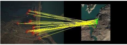
Figure 6. The results of matching process for selected UAV image frame against to database; left: UAV image frame and
right: reference image
Figure 7. Some examples of matched pairs; up: image frame, and bottom: reference image
D
S
C
0
8
6
3
8
f
ra
m
e
Figure 8. Geo-located image boundaries resulted from coarse (red) and fine (green) geo-location stages for four example
frames shown in Figure 5
(a)
(b)
(c)
Figure 9. Geo-referenced image frames overlaid on (a) reference image resulted from (b) initial coarse and (c) fine EOP
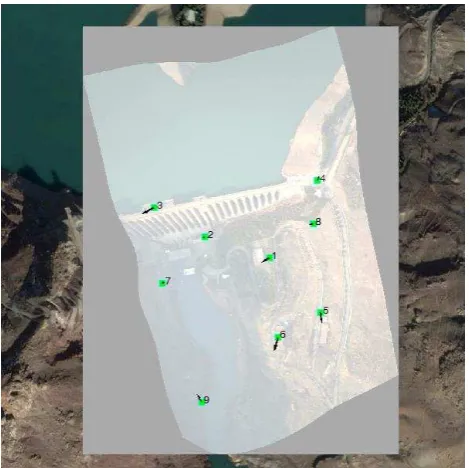
In order to provide a context for statistical analysis, nine distinct point features with proper distribution over sample geo-located image frames were measured. These frames have obtained by applying coarse and fine geolocation procedures on one sample UAV image frame. Calculated locations of these points then compared with their reference locations obtained from the database. Horizontal residual vectors of these points are depicted in Figures 10 and 11 for the cases of coarse and fine geo-location procedures, respectively. As it is seen, residuals after applying the fine geo-location process have been reduced considerably.
Resulted differences then used to extract statistical parameters indicating performance of the intended process. The statistical parameters, Root Mean Square Error (RMSE), Mean Absolute Error (MAE), minimum (Min), and maximum (Max) values are then calculated for X, Y, and Z coordinate components, also for horizontal (2D), and three dimensional (3D) coordinates. These parameters are illustrated in Tables 1 and 2 for the cases of coarse and fine geo-location procedures, respectively. As it can be seen, applying the fine geolocation process has improved the positional accuracy by the order of 100 m, approximately. For example, by applying fine geolocation process the RMSE values for horizontal and 3D locations will be 14.349 m and 14.476 m respectively, in comparison with 114.765 m and 119.605 m in the case of coarse geo-location process.
Figure 10. Residual vectors obtained by differencing control point positions in the case of geo-located image resulted from
coarse geo-location process
Figure 11. Residual vectors obtained by differencing control point positions in the case of geo-located image resulted from
fine geo-location process
Table 1. Statistical parameters in the case of applying coarse geolocation process
Table 2. Statistical parameters in the case of applying fine geolocation process
Results indicated that the proposed method can improve the geolocation accuracy considerably. Using this method, geo-location of UAV images will be performed with the accuracy order comparable to accuracy of used georeferenced database. Experimental results demonstrated the potential of the proposed method in accurate geolocation of UAV images.
It should be noted that although the results of geo-locating the example frames presented here are satisfactory, these frames have common features that simplifies the geo-location process of them using proposed method. First, these frames have sufficient distinct feature points that facilitate matching process. Second, they are all near vertical image frames so the orientation parameters of them are all near zero, i.e. the initial orientation parameters are almost near true values. In natural environments it is common that image frames have not sufficient distinctive feature points. In these cases one must use alternative robust features such as structural ones in the matching stage. Also, in the case of UAV data acquisition procedures it is common to have highly oblique image frames, which for geo-location need accurate feature points with good dispersion over the frame.
4. CONCLUSION
In this paper we proposed a procedure for 3D geo-location of UAV image frames using a geo-referenced database consisting of geo-referenced imagery and DSM.
Experimental results demonstrated the potential of the proposed method in accurate geo-location of UAV images when they have sufficient number and dispersion of feature points. Results indicated that the proposed method can improve the geo-location accuracy considerably. Using this method, geo-location of UAV images will be performed with the accuracy order comparable to accuracy of used geo-referenced database.
However, in the cases with not sufficient feature points matching process will be failed, or even if not, erratic dispersion of feature points in the image will prevent accurate solving of attitude parameters. Developing more robust matching strategies would be interesting issue for the next researches.
REFERENCES
Arun, A., Yadav, M. M., Latha, K., & Kumar, K. S., 2012. Self directed unmanned aerial vehicle for target geo-localization system. In Computing, Electronics and Electrical Technologies (ICCEET), 2012 International Conference on (pp. 984-990). IEEE.
Bang, K. I., Habib, A. F., Kim, C., & Shin, S., 2007. Comprehensive analysis of alternative methodologies for true ortho-photo generation from high resolution satellite and aerial imagery. In American Society for Photogrammetry and Remote
Sensing, Annual Conference, Tampa, Florida, USA, May, pp.
7-11.
Barber, D. B., Redding, J. D., McLain, T. W., Beard, R. W., & Taylor, C. N., 2006. Vision-based target geo-location using a fixed-wing miniature air vehicle. Journal of Intelligent and
Robotic Systems, 47(4), 361-382.
Bollard-Breen, B., Brooks, J. D., Jones, M. R., Robertson, J., Betschart, S., Kung, O., ... & Pointing, S. B., 2015. Application of an unmanned aerial vehicle in spatial mapping of terrestrial biology and human disturbance in the McMurdo Dry Valleys, East Antarctica. Polar Biology, 38(4), 573-578.
Heintz, F., Rudol, P., & Doherty, P., 2007. From images to traffic behavior-a uav tracking and monitoring application.
In Information Fusion, 2007 10th International Conference
on (pp. 1-8). IEEE.
Kumar, R., Samarasekera, S., Hsu, S., & Hanna, K., 2000. Registration of highly-oblique and zoomed in aerial video to reference imagery. In Pattern Recognition, 2000. Proceedings.
15th International Conference on (Vol. 4, pp. 303-307). IEEE.
Kushwaha, D., Janagam, S., & Trivedi, N., 2014. Compute-Efficient Geo-Localization of Targets from UAV Videos: Real-Time Processing in Unknown Territory. International Journal of Applied Geospatial Research (IJAGR), 5(3), 36-48.
Lowe, D. G., 2004. Distinctive image features from scale-invariant keypoints. International journal of computer vision, 60(2), 91-110.
Neitzel, F., & Klonowski, J., 2011. Mobile 3D mapping with a low-cost UAV system. Int. Arch. Photogramm. Remote Sens. Spat. Inf. Sci, 38, 1-6.
Nex, F., & Remondino, F., 2014. UAV for 3D mapping applications: a review. Applied Geomatics, 6(1), 1-15.
Rango, A., Laliberte, A., Steele, C., Herrick, J. E., Bestelmeyer, B., Schmugge, T., ... & Jenkins, V., 2006. Using unmanned aerial vehicles for rangelands: current applications and future potentials. Environmental Practice, 8(03), 159-168.
Remondino, F., Barazzetti, L., Nex, F., Scaioni, M., & Sarazzi, D., 2011. UAV photogrammetry for mapping and 3d modeling– current status and future perspectives. International Archives of the Photogrammetry, Remote Sensing and Spatial Information
Sciences, 38(1), C22.
Saari, H., Pellikka, I., Pesonen, L., Tuominen, S., Heikkilä, J., Holmlund, C., ... & Antila, T., 2011. Unmanned Aerial Vehicle (UAV) operated spectral camera system for forest and agriculture applications. In SPIE Remote Sensing (pp. 81740H-81740H). International Society for Optics and Photonics.
Semsch, E., Jakob, M., Pavlíček, D., & Pěchouček, M., 2009. Autonomous UAV surveillance in complex urban environments.
In Web Intelligence and Intelligent Agent Technologies, 2009.
WI-IAT'09. IEEE/WIC/ACM International Joint Conferences on (Vol. 2, pp. 82-85). IET.
Wischounig-Strucl, D., & Rinner, B., 2015. Resource aware and incremental mosaics of wide areas from small-scale UAVs. Machine Vision and Applications, 1-20.