MODELS FOR PHOTOGRAMMETRIC PROCESSING OF INFORMATION FROM
“RESOURCE-P” SATELLITES
V. Poshekhonov a, V. Eremeev a, А. Kuznetcov a, A. Kochergin a*
a
Ryazan State Radio Engineering University, 390005, Russia, Ryazan, 59/1, Gagarin Str. – [email protected]
Special Sessions, SpS 8
KEY WORDS: Geolocation, Scanning Sensors, Measurement Information, Interior And Exterior Orientation Parameters, Geometric Calibration
ABSTRACT:
The present paper provides information about imagery and navigation systems of the Russian high resolution satellites "Resource-P". Models of image geolocation used for photogrammetric processing of information from all types of imagery systems are designed. Design of these models is based on two task solutions: correct processing of the measurement information and geometric calibration of the imagery systems.
It is shown that for high-precision interior orientation parameters adjustment of the high-resolution "Geoton" instrument the method of self-calibration should be used. The technology of calibration activities is considered. Distinctive features of calibration of the hyperspectral and wide-swath imagery systems are noted. It is represented in the paper that after calibration the root mean square error (RMSE) of measured geodetic coordinates of objects on images do not exceed 10 m.
Examples of the obtained models practical application for photogrammetric processing of images from “Resource-P” satellites are shown.
*
Corresponding author
1. INTRODUCTION
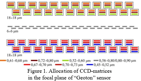
In 2013 and 2014 two Russian Earth remote sensing satellites “Resource-P” №1 and №2 were successfully launched. Satellite imagery instruments are a high spatial resolution sensor (“Geoton”) [Arkhipov and others, 2014], hyperspectral imagery instrument (HSI) and a complex of wide-swath multispectral imagery (CWMI). “Geoton” sensor forms an image in the panchromatic channel having resolution 0.7 m (nadir) and in 6 narrow spectral ranges having resolution 2.1 m in the 38 km swath. Figure 1 demonstrates a sensor focal plane and shows CCD-matrices located according to the staggered principle.
Figure 1. Allocation of CCD-matrices in the focal plane of “Geoton” sensor
Hyperspectral imagery instrument acquires images having spatial resolution about 30 m in 130 spectral channels in the 30 km swath. CWMI includes sensors of high (HR) and average (AR) spatial resolution each of which carries out imagery in the panchromatic channel (resolution 12/60 m) and 5 multispectral channels (resolution 24/120 m) in the 96/480 km swath.
Measurement of the spatial position and attitude of satellite is carried out by GLONASS/GPS receiver, four star trackers and
angular velocity measuring instrument (AVMI). Measurement information is transmitted at every imagery route which can contain video data from one or several scanning sensors.
For photogrammetric processing of the Earth surface images from all types of satellite imagery instruments the present paper solves the following tasks:
– development of models for video data geolocation taking into consideration specific character of the imagery instrument operation and also algorithms of the measurement information processing;
– development of technology for the geometric calibration of imagery instruments based on geometric calibration ranges; – indication of results of the practical application of processing models for acquisition of output information products.
2. MODEL OF VIDEO DATA GEOLOCATION
Mathematical model of the geolocation is a basis of all types of photogrammetric processing of video data. It describes a viewing ray orientation of the sensor and allows calculating geodesic coordinates
, for an arbitrary pixel
m,n taking into account terrain height h on the coordinate systems WGS-84 and PZ-90. Input data for the model are dynamic parameters of the exterior satellite orientation and static parameters of the interior orientation of each sensor. Taking into consideration these parameters for an arbitrary pixel
m,n , the following is determined in the Earth centered rotational coordinate system: unit vector rE
m,n of direction cosines of the viewing ray, and also spatial position of the imagery instrument p
t at the corresponding moment of time tt0n of n-line formation,where t0 - time of the imagery beginning, - scanning
The International Archives of the Photogrammetry, Remote Sensing and Spatial Information Sciences, Volume XLI-B6, 2016 XXIII ISPRS Congress, 12–19 July 2016, Prague, Czech Republic
This contribution has been peer-reviewed.
frequency of the image formation. Vector rE
m,n is calculated according to formula:
mn ES
t SC C
mE R R r
r , , (1) where RSC – a transfer matrix from the camera coordinate system to the satellite coordinate system determined by interlock angles of the imagery instrument: rC
m – a vector of direction cosines in the camera coordinate system determined using a model of the imagery instrument.Matrix RES
t of transfer from the satellite coordinate system to the Earth centered rotational coordinate system at the specified moment of time and vector p
t are determined according to results of the measurement information processing. In the general form, the model of image geolocation is described by functions
m,n,h,u
, F
m,n,h,u
defining geodesic coordinates for a point of cross of the viewing ray and reference ellipsoid at the specified height h for pixel
m,n , where u – a vector of input parameters describing elements of the external and interior orientation of the imagery system. Values of functions and F are found by the solution of equation
t s E
mnE p r ,
p (2)
relative to variable s determining the viewing ray length together with the equation of reference ellipsoid. The component of vector rC
m in formula (1) is determined for each CCD-matrix taking into account the lens distortion [Brown, 1966].3. ALGORITHM OF MEASUREMENT INFORMATION PROCESSING
Measurements of spatial position of the satellite center of masspi
X,Y,Z
and its velocity vi
Vx,Vy,Vz
are obtained from GLONASS/GPS receiver at the discrete moments of timei
t , i=1,2... These measurements are approximated by the model of satellite movement taking into account external terrestrial gravitational fields and disturbances from the Sun and Moon in order to find vector p
t . Vectors of initial conditions p0, v0and time t0 for achievement of the best approximation are determined on the basis of functional:
Information of the satellite attitude has a number of distinctive features. Firstly, determination of spacecraft axis orientation by star trackers has different precisions. Secondly, frequency of measurements by star trackers is significantly lower than frequency of the AVMI operation. It is reasonably to use data on angular velocity from AVMI for approximation of measurements obtained by star trackers in order to increase precision of the attitude determination at the arbitrary moment of time.
Flight tests determined that using obtained models, geolocation errors had exceeded 300 m. The reason was in inaccurate values of interior orientation parameters and also interlock angles of star trackers and imagery instruments. The technology of geometric calibration for the geolocation model using reference information has been developed for improvement of these parameters.
4. GEOMETRIC CALIBRATION OF IMAGERY SYSTEMS
Geometric calibration of “Geoton” instrument has the following peculiarities. Discrepancy of coordinates of observable image points was caused by random errors of measurements of the angular and linear satellite position within the imagery and also by systematic errors. These errors can be separated only by processing a set of images. Besides, a great number of ground control points having known geodesic coordinates and height should be identified on reference images of geometric calibration ranges. Since it was impossible to obtain enough number of control points, the method of self-calibration was used [Faugeras, 1993; Grodecki, Lutes, 2005].
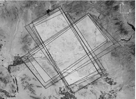
For the method of self-calibration, 10 crosswise imagery routes were made. In this case tie points on a couple of cross routes connect images from each CCD-matrix of one route with images of all CCD-matrices of the second route. Figure 2 represents a layout of 9 imagery routes of the geometric calibration range.
Figure 2. Layout of imagery routes of the geometric calibration range for adjustment of interior orientation parameters
of the “Geoton” instrument
For geometric calibration of HSI sensor, the Earth surface was synchronously imaged by the HSI and “Geoton”. And structurally reconstructed image from the “Geoton” sensor was used as a reference one. Coordinates of tie points and ground control points were measured on the reference image and images from the HSI sensor.
For geometric calibration of CWMI instruments orthorectified images from the «Lansat 8» system [Storey et al., 2014] were used. Height at ground control points was measured according to the digital elevation model SRTM.
5. RESULTS OF PRACTICAL APPLICATION OF PHOTOGRAMMETRIC PROCESSING MODELS
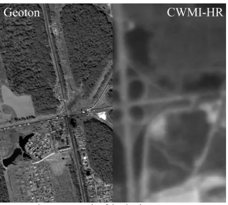
Software for the ground processing of information obtained from “Resource-P” №1 and №2 spacecrafts has been developed on the basis of obtained models of geolocation. Experiments have shown that root mean square error of determination of the Earth surface object coordinates from “Geoton” instrument images do not exceed 10 m. For HSI and CWMI these errors do not exceed one pixel. It allows combining images from various types of scanning devices without any additional operations (Figure 3).
The International Archives of the Photogrammetry, Remote Sensing and Spatial Information Sciences, Volume XLI-B6, 2016 XXIII ISPRS Congress, 12–19 July 2016, Prague, Czech Republic
This contribution has been peer-reviewed.
Figure 3. Example of the simultaneous output of data from “Geoton” and CWMI-HR
The task of forming structurally reconstructed image from separate CCD-matrices of “Geoton” instruments was solved using high-precision models of geolocation at the qualitatively new level (Figure 4). In [Eremeev et al., 2014] it is shown that multispectral Earth surface images not containing elevation distortions are also combined automatically.
Figure 4. Multiscanned and structurally reconstructed image
6. CONCLUSION
Experimental research results have confirmed stability in time of imagery instruments interior orientation parameters and setting angles of star trackers adjusted by geometric calibration. It allows widely using photogrammetric processing software of data from “Resource-P” spacecraft in a number of receiving centers of the Russian Federation.
REFERENCES
Arkhipov S.A., Baklanov A.I., Gerasimenko V.V. Multispectral optical-electronic instruments “Geoton” of the spacecraft “Resource-P” // Research of the Earth from space. 2014. № 2. P. 44-54.
Brown D.C. Decentering distortion of lenses // Photogrammetric Engineering. 1966. № 7. P. 444-462.
Eremeev V., Kuznecov A., Myatov G., Presnyakov O., Poshekhonov V., Svetelkin P. Image structure restoration from sputnik with multi-matrix scanners, Proc. SPIE 9244, Image and Signal Processing for Remote Sensing XX, 92440F (October 15, 2014); doi:10.1117/12.2066631; http://dx.doi.org/10.1117/12.2066631.
Faugeras O. Three Dimensional Computer Vision // MIT Press. 1993. 695 p.
Grodecki J., Lutes J. IKONOS Geometric Calibrations // ASPRS Annual Conference. 2005.
Storey J., Choate M., Lee K. Landsat 8 Operational Land Imager On-Orbit Geometric Calibration and Performance // Remote Sens. 2014. № 6(11). P. 11127-11152.
The International Archives of the Photogrammetry, Remote Sensing and Spatial Information Sciences, Volume XLI-B6, 2016 XXIII ISPRS Congress, 12–19 July 2016, Prague, Czech Republic
This contribution has been peer-reviewed.