THE GEOSPECTRAL CAMERA: A COMPACT AND GEOMETRICALLY PRECISE
HYPERSPECTRAL AND HIGH SPATIAL RESOLUTION IMAGER
B. Delauré a, B. Michiels a, J. Biesemans a, S. Livens a, T. Van Achteren a
aVITO, Flemish institute for technological research, Mol, Belgium – (bavo.delaure, bart.michiels, jan.biesemans, stefan.livens, [email protected])
KEY WORDS: Hyper spectral, multispectral, georeferencing, multiresolution, camera
ABSTRACT:
Small unmanned aerial vehicles are increasingly being employed for environmental monitoring at local scale, which drives the demand for compact and lightweight spectral imagers. This paper describes the geospectral camera, which is a novel compact imager concept. The camera is built around an innovative detector which has two sensor elements on a single chip and therefore offers the functionality of two cameras within the volume of a single one. The two sensor elements allow the camera to derive both spectral information as well as geometric information (high spatial resolution imagery and a digital surface model) of the scene of interest. A first geospectral camera prototype has been developed. It uses a linear variable optical filter which is installed in front of one of the two sensors of the MEDUSA CMOS imager chip. A accompanying software approach has been developed which exploits the simultaneous information of the two sensors in order to extract an accurate spectral image product. This method has been functionally demonstrated by applying it on image data acquired during an airborne acquisition.
1. INTRODUCTION
1.1 Hyperspectral imaging
Hyperspectral imaging is a powerful technique for monitoring the earth in a variety of ways through environmental assessments, vegetation species monitoring, health and land use management studies, etc.. This is done through image acquisition in many narrow spectral bands to detect narrow band features and subtle variations in the reflectance spectra of natural objects. Although conceptually very powerful, acquiring narrow spectral band images from a moving platform faces an unavoidable trade-off between:
high spatial resolution to avoid intermixing of spectral signatures of small scale features
high signal to guarantee that the spectral signature can be effectively discriminated from background noise
Hyperspectral instruments for earth observation are often built a prism or grating based pushbroom spectrometers which are coupled to a complex optical system. They also rely on a stabilised platform and high quality inertial navigation systems to achieve precise georeferencing of their line-based image data. Both aspects limit the use of these instruments on mass and volume constrained platforms.
1.2 Linear variable filters
Recent developments in optical filter deposition techniques open opportunities for reducing the size and complexity of hyperspectral imagers. One technology is of particular interest for building compact instruments: linear variable interference filters (LVF). The filters act as Fabry-Perot interference filters. The thickness of the cavity varies linearly along one dimension, transmitting light of specific wavelengths to a 2D array of detectors. The filter is positioned very near to the sensor.
This configuration allows to create a very compact instrument, and it simplifies the optical layout. Another advantage is that it is possible to use the focal plane only partially for spectral imaging and partially for other purposes.
A good overview of spectrometers employing interference filters, is given in (Carmo, 2012). LVF instruments are also being applied to remote sensing. One example is the- HySI-T instrument of the Indian Mini Satellite-1 (Kumar, 2005), which images 64 bands in the range 400 - 920 nm, with spectral resolution better than 15 nm. A linear variable filter based compact hyperspectral imager has been proposed in (Maresi, 2009). A breadboard of a compact hyperspectral imager has been developed under ESA contract and a proposition for an improved instrument design (Moreau, 2012). Due to recent advancements in filter deposition technology Fabry-Perot based linear variable filter are also deposited directly on top of image sensors (Tack, 2012).
1.3 LVF hyperspectral image reconstruction
A fundamental difference between a traditional pushbroom hyperspectral imager and an LVF based system is the way in which the spectral information is acquired. A traditional pushbroom imager selects by means of a slit in the optical system one spatial line on the ground for which the light is dispersed and the light is projected at a 2-dimensional detector. In one snapshot all spectral information of the selected spatial line on the ground is acquired. By moving the instrument a 2D region can be scanned.
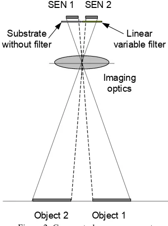
In an LVF imager, the acquisition principle is different as shown in Figure 1. The instrument is looking at a 2-dimensional scene on the earth. The spectral filter is positioned very near to the sensor. As a result the different lines of the sensor receive light of different narrow spectral bands. One snapshot acquires a 2-D scene, but with every line (in the across flight direction)
corresponding to a different spectral band. As a consequence a scanning motion is required to retrieve the complete reflectance spectrum of a certain point on the earth. The reconstruct the spectrum, very accurate knowledge of position and attitude is required. A method of accurate reconstruction of hyperspectral image product acquired with a linear variable filer is proposed in (Sun, 2001) which makes use of a separate camera apart from the spectral camera.
Figure 1: concept of a linear variable filter based spectrometer
1.4 Overview
In this paper, we describe a novel camera concept which we call
“geospectral camera”. Within the volume of a digital camera, the instrument allows to generate geometrically precise hyperspectral image data combined with high spatial resolution images. In the field of earth observation this camera is therefore ideally suited for mass and volume constrained platforms like compact remotely piloted aircraft systems (RPAS) or very small satellites. The geospectral camera concept is patented (Biesemans, 2009).
2. THE GEOSPECTRAL CAMERA
The unique characteristics of the geospectral camera originate from the innovative detector-filter configuration. The detector consists of two 2-dimensional sensor elements on a single image sensor chip. Since the two sensor elements have been processed on one single die with lithographic accuracies, they are perfectly aligned with respect to each other and their relative position within the focal plane of the camera is known very accurately. Furthermore, the spectral sensor element of the
camera, the “spectral sensor”, is equipped with optical filters
positioned just in front of the detector. These filters typically have a 2-dimensional structure consisting of narrow spectral bandpass filters, of which the central wavelength is uniform in one direction and variable in the other direction. This variation can be either continuous as in the case of a hyperspectral imager or in discrete steps in case of a multispectral filter consisting of for instance 10 bands. The second sensor element is a panchromatic or spectrally broadband frame sensor which is
called the “geometric sensor”. The use of optical filters just in front of the sensor allow to keep the optical system simple and compact which make the camera attractive for use on small remotely piloted aircraft.
Figure 2: Geospectral camera concept
As explained above with this filter concept the complete reflectance spectrum of one spatial point on the ground can only be reconstructed by combining the spectral line information in different images acquired while scanning the camera over this point. It is clear that this process requires a very accurate determination of the camera exterior orientation. The geo-spectral camera is well-suited by design to solve this challenge because the fact that both sensor elements are tightly coupled on a single die can be exploited.
The narrow spectral band filter limits the amount of light falling on the spectral sensor element. Therefore it needs to be configured for longer exposure times and/or pixel binning needs to be employed to achieve acceptable signal to noise ratios. The geometric sensor element is operated with much shorter exposure times and captures the geometric information of the scene at high spatial resolution.
The frame images acquired by the geometric sensor are used to derive the exterior camera parameters. Due to the strong geometric link between the two sensors on a single chip also the orientation of the spectral sensor can be derived very precisely, required to be able to derive an accurate hypercube This approach relaxes the specifications of the inertial navigation system to the level of typical devices used in handheld mobile devices and corresponding the mass of the total system.
Apart from using the images of sensor element 1 to derive the exterior camera orientation for reconstructing the spectral data the geospectral camera is able to also derive additional information by design:
a photogrammetric image composite can be derived with high spatial resolution. This can be used to spatially sharpen or fuse with the hyperspectral image product
a digital surface model which is derived within the same flight mission as the spectral image product
SEN 1
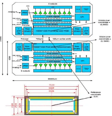
Figure 3 layout of the focal plane of an example of a geospectral camera
3. PROTOTYPE OF THE GEOSPECTRAL CAMERA
VITO has developed a breadboard version of the geospectral camera concept. It makes use of the unique MEDUSA CMOS image sensor which contains two sensor elements of each 10000 x 1200 pixels with 5.5 µm pitch on a single imager chip (Delauré, 2009) which is designed for a lightweight high resolution camera system for a stratospheric solar powered unmanned aerial vehicle (Van Achteren, 2013). The maximum frame rate at which the sensor can be operated is 30 fps. The image sensor chip is shown in Figure 4. In the default configuration one sensor element is equipped with an RGB Bayer filter, one sensor element is panchromatic. A schematic layout of the silicon die with the two sensors is illustrated in Figure 5. The distance between the two sensors is 700 µm.
Figure 4 MEDUSA CMOS sensor chip with 2 sensors on a single die
Figure 5 schematic layout of the MEDUSA CMOS sensor with the 2 independent sensors on one single chip
Figure 6 example image acquired with the MEDUSA CMOS sensor from an airborne flight. Top: colour image acquired with the RGB sensor, Bottom: image acquired with the panchromatic
sensor.
The current version of the geospectral camera is equipped with an optical filter covering the range 450-900 nm in more than 40 bands. The FWHM of the spectral response of the filter is between 17 – 19 nm and the slope of the linear variation is around 60 nm/mm. The filter is deposited on a glass substrate which is placed in front of the panchromatic sensor element. The response of the linear variable filter is shown in Figure 7. The second sensor element is in this case the RGB sensor. One of the first images acquired with the geospectral camera prototype is shown in Figure 8. The target consisted of a frame of Lego bricks organised in black-white structures and red green blue structures. Within certain parts of the Lego frame real objects have been installed like leafs, an Erbium and spectralon target.
Figure 7: spectral response measurement of the linear variable filter measured at ten points along the variable axis of the filter
Figure 8 image acquired with the geospectral camera. Top: colour image acquired with the RGB sensor, Bottom: spectral image acquired with the panchromatic sensor with the linear variable filter.
4. AIRBORNE FLIGHT: MEDUSA CASE STUDY
In parallel with the development of the prototype camera a method has been developed to reconstruct a spectral image product based on the individual images acquired with the LVF covered detector. The method exploits the unique detector concept in which 2 sensor elements are processed with lithographic accuracies on one imager chip. This way the relative position of the 2 sensor elements with respect to each other is accurately known by design.
The method has been applied on airborne data acquired with the MEDUSA CMOS sensor during a balloon flight above
0 10 20 30 40 50 60 70 80
400 500 600 700 800 900 1000
T
ra
n
s
m
is
s
io
n
(%
)
Wavelength (nm)
Linear variable filter response
Belgium. During this flight at an altitude of 1500 m the MEDUSA engineering model camera was equipped with an optical system of 80 mm focal length resulting in a ground sampling distance of around 10 cm, a swath of 1000 m and an image size along the flight direction of 120 m for each of the two sensor elements. The camera was operated at a frame rate of 1 fps. The MEDUSA engineering model contains an AsteriX2 dual frequency GPS receiver of Septentrio and a lightweight ISIS-IMU of Inertial Sciences. Both devices are hardware synchronised with each other.
Figure 9 shows the layout of the focal plane of the MEDUSA engineering model camera with the 2 sensor elements (1 panchromatic and 1 with a Bayer RGB filter). To be able to evaluate the reconstruction method on a line based spectral imager the images from the RGB sensor have been converted artificially into images from a 3-band spectral filtered sensor. Each band consists of 10000 x 400 pixels of which the spectral content is calculated by interpolating the nearest neighbour pixel content. This layout is shown in Figure 10. The resulting spectral image product of the 3-band spectral filtered sensor is a colour composite.
Figure 9 layout of the focal plane of the MEDUSA engineering model camera
Figure 10 layout of the artificial 3-band spectral filter used for the MEDUSA case study
In order to reconstruct the spectral image product each colour image is separated into 3 spectral frames of each 10000x400 pixels. Those individual spectral frames are grouped per spectral channel and projected onto a common grid making use of the exterior orientation of the camera at the instance of exposure and the digital surface model. This way for each
spectral band one composite is generated. The resulting colour image is created by reconstructing the colour information for each pixel in the grid from the 3 spectral composites.
In order to evaluate the reconstruction method of the geospectral camera the data has been processed using two sets of position and attitude data:
M1: Using GPS and IMU data directly as position and attitude data for the project
M2: determination of exterior orientation and position of the camera at the instance of sensor exposure derived from block bundle adjustment on the panchromatic image data set
The results are reported in the next sections.
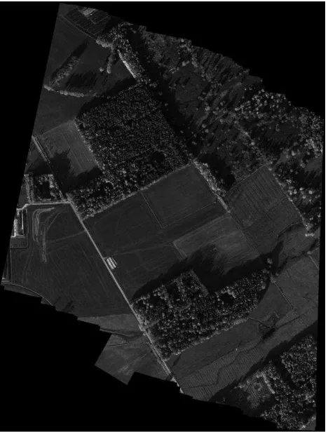
Figure 11 panchromatic composite at 10 cm GSD derived from the panchromatic sensor data
5. RESULTS
This section describes the first results realised with the method to reconstruct the spectral image product using the orientation determined from the panchromatic images. For visualisation of the output of the geospectral camera a test region was selected during the balloon mission. As mentioned above apart from the spectral image product the geospectral camera is able to supply high spatial information and height information of the scene surface. Figure 11 shows a mosaic of panchromatic data as acquired with the MEDUSA engineering camera flight along 1 flight strip. The ground sampling distance of the panchromatic images is 10 cm. The mosaic was produced by means of AGISOFT photoscan. Apart from the panchromatic mosaic a digital surface model can be extracted which is shown in Figure 12.
Figure 12 digital surface model derived from the panchromatic images of the MEDUSA engineering camera
To reconstruct the spectral image product the two methods described above have been used. The image reconstruction making use of position and attitude data derived directly from GPS and IMU is illustrated in Figure 13. It is clear from this image that the GPS and IMU accuracy is insufficient to reconstruct the spectral content of the reconstructed image product accurately. It should be noted that at the edges of the colour composite the colour reconstruction has failed because of the fact that certain spatial regions are not covered by the three spectral bands. This makes it off-course impossible to retrieve the correct spectral information at those positions. Those effects are present in both methods to reconstruct the spectral information and are boundary effects. They do not affect the colour reconstruction in the central part of the reconsctructed image.
In the center of the reconstructed colour image the impact of in correct co-registration between the different bands can be observed. This is most prononounced along transitions between different land covers but is present over the complete area. The effect is of the order of several tens of pixels. As a consequence the spectral information in the end image product is largely distorted and is not representative any more for the spatial location.
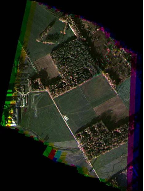
Figure 14 shows the resulting colour image when using the exterior orientation of the camera derived from block bundle adjustement operation applied on the panchromatic images of which the composite is shown in Figure 11. It is clear from Figure 14 that the spectral misregistration error between the different spectral bands is significantly reduced and as a consequence allows a more representative reconstruction of the colour information. The current accuracy of georeferencing of the three spectral frames is assumed to be limited by the interior
camera parameters which have been determined from the block bundle adjustment operation at the panchromatic images.
Figure 13 colour image reconstruction of the 3 bands making use of position and attitude directly from GPS and IMU.
Figure 14 colour image reconstruction of the 3 bands making use of the exterior camera parameters derived from the block bundle adjustment proces applied on the panchromatic data set.
6. CONCLUSIONS AND OUTLOOK
Within this paper the geospectral camera concept has been presented which makes use of an innovative approach with 2 sensor elements on one single chip. The application field of the camera concept is primarily focussed for spectral imaging executed on mass and volume constrained platforms like for instance small unmanned aerial vehicles. The camera concept is suitable because of its compact spectral unit (using an optical filter just in front of the detector) and its reduced requirements on the performance of the inertial navigation system which is required for georeferencing the spectral data. Apart from the multi- or hyperspectral image product the camera is able to supply a high spatial resolution image product and a digital surface model. A first prototype of the geospectral camera has been integrated making use of a linear variable filter which is combined with the MEDUSA CMOS sensor which contains two independently controllable CMOS sensors on 1 chip. An method has been derived exploiting the presence of the two sensors to be able to extract an accurate spectral image product. This approach has been functionally demonstrated on airborne data acquired with the MEDUSA engineering camera confirming the advantage of the second sensor element to retrieve geometrically correct spectral data from a linear variable filter based instrument.
At short term the spectral image product reconstruction method will be refined taking into account a more suitable set of interior orientation parameters of the camera model. This will improve the georeferencing of each spectral band individually. In a second phase a redesign of the camera will be executed to optimise the different subsystems of the camera and for being used in a geospectral camera.
7. REFERENCES
Biesemans J., Delauré B., Michiels, B., “Geometric Referencing of Multi-spectral data”, Patent application WO 2011/073430 A1, 23 June 2011
Carmo, J. P., Rocha, R. P., Bartek, M., de Graaf, G., Wolffenbuttel, R. F., Correia, J. H., A review of visible-range Fabry–Perot microspectrometers in silicon for the industry, Optics & Laser Tech, Vol. 44, Issue 7, Oct. 2012, 2312–2320
Delauré, B., Livens, S., Everaerts, J., Kleihorst, R., Schippers, G., De Wit, Y., Compiet, P., Banachowicz, B., 10000 pixels wide CMOS frame imager for earth observation from a HALE
UAV”, Proc. SPIE 7474, Sensors, Systems, and Next-Generation Satellites XIII, 74741D (September 22, 2009), Berlin, Germany
Kumar, A. S. K. and A Roy Chowdhury, A. R., Hyper-Spectral Imager in visible and near-infrared band for lunar compositional mapping, J. Earth Syst. Sci. 114, No. 6, pp. 721–724, Dec. 2005
Maresi L., Taccola M., Kohling M., Livens S., “PhytoMapper - Compact Hyperspectral Wide Field of View Instrument, Proc. Of 7th IAA Symposium on Small Satellites for Earth Observation, May 04 - 08, 2009, Berlin, Germany
Moreau V., DeClercq C., Lousberg G., Maresi L., Delauré B.,
“Development of a compact hyperspectral / panchromatic
imager for management of natural resources”, Proc. Small Satellites Systems and Services - The 4S Symposium 2012, 4 - 8 June 2012, Portoroz, Slovenia
Sun X., "Computerized component variable interference filter imaging spectrometer system method and apparatus," US Patent 6211906 (2001).
Tack N., Lambrechts A., Soussan P. and Haspeslagh L., A compact, high-speed, and low-cost hyperspectral imager, Proc. SPIE 8266, Silicon Photonics VII, 82660Q (Feb. 9, 2012);
Van Achteren T. , Delauré B., Everaerts J., Lewyckyj N., Michiels B., “A lightweight and wide swath UAV camera for high resolution surveillance missions”, Proc. SPIE Defense and Security, Baltimore, USA, to be published (2013)