INVESTIGATIONS ON A COMBINED RGB / TIME-OF-FLIGHT APPROACH FOR
CLOSE RANGE APPLICATIONS
H. Hastedt a, Th. Luhmann a
a IAPG, Jade University of Applied Sciences, Ofener Str. 16/19, 26121 Oldenburg, Germany
Commission V, WG V/5
KEY WORDS: Close Range, Metrology, Vision, Image, Multisensor, Calibration, Fusion
ABSTRACT:
3D surface and scene reconstruction for close range applications mainly rely on high resolution and accurate system devices and powerful algorithms. Camera systems based on the time-of-flight principle allow for real-time 3D distance measurements. Unfortunately these devices are limited in resolution and accuracy. But applying calibration models and combining with high-resolution image data offers a promising approach in order to form a multisensor system for close range applications. This article will present investigations on such a multisensor system. Different options on data fusion processing of distance information and high-resolution color information in order to generate dense 2½ D and 3D point clouds will be presented. The multisensor system is calibrated with respect to its interior and exterior orientation. The time-of-flight distance information is optimized extracting best information of different data captures with a set of integration times following the principle of high dynamic range imaging. The high-resolution RGB image information is projected into object space and intersected with the object surface from the time-of-flight camera. First results of this solution on dense monoplotting and its verification will be presented.
1. INTRODUCTION
The reconstruction of surfaces and scenes in three-dimensional object space is one key issue in close-range metrology. High-resolution sensors combined with powerful algorithms fulfilling accurate measurement results are requested in practice. On the one hand dense, accurate and verified 3D models for metrology purposes are required. On the other hand dense, coloured and realistic textured 3D models for 3D visualizations of, for instance, 3D city models or other complex objects are desired. Applications can be identified for modeling of static objects like building reconstructions, statue or artifact modeling or mechanical engineering. Furthermore dynamic scenes like collision estimation, deformation measurements or object tracking and navigation need to be supported by appropriate sensor systems too.
Laser scanning techniques are established approaches for the task of 3D reconstruction. Laserscanners provide direct 3D point data, whereby coloured 3D point clouds can be determined by a combined frame camera. Nowadays this is supported by most system suppliers. Different investigations have been carried out with respect to not only colouring the 3D point cloud but use monoplotting techniques to register and map the 3D laserscanning information to the frame camera data using different interpolation methods. Schwermann and Effkemann (2002) report on a combined monoplotting technique within the program system PHIDIAS. They established the method for selected image points within a CAD environment using images and laserscanning data oriented within the same object coordinate system. Ressl et al. (2006) present a similar solution with a robust and automatic estimation of the corresponding object plane of manually selected image points. Projecting the 3D points into image space and interpolating 3D information for each image point from the mapped object points is denoted as '3D image' by Abdelhafiz (2009). However, laserscanners are limited to the
acquisition of static scenes respectively low-dynamic scenes within their measuring frequency.
For dynamic processes stereo camera systems are useful measuring devices. 3D object modeling relies on sufficiently textured surfaces in order to automate the 3D surface reconstruction by image-based matching algorithms. A manual photogrammetric point-by-point solution is far beyond efficient work. Alternatively camera systems based on the time-of-flight principle allow for real-time 3D distance measurements without the necessity of textured surfaces. Unfortunately these devices are limited in resolution and accuracy. But applying calibration models and combining with high-resolution image data offers a promising approach in order to form a multisensor system for dynamic close range applications. Lindner (2010) and Kahlmann (2007) introduce error models and compensation methods for time-of-flight camera systems. Boehm and Pattison (2010) estimate the accuracy of exterior orientation of range cameras and suggest not to establish it with the range camera data itself. Fuchs and May (2007) describe a calibration method based on plane object verification with time-of-flight depth information for surface reconstruction. Van den Bergh and Van Gool (2011) report on an approach using RGB image information for pre-segmentation and subsequent hand gesture tracking. While Lindner et al. (2007) and Reulke (2006) introduce data fusion approaches using pre-calibration, Huhle et al. (2008) present a combined local registration model using depth and colour information. A similar registration method using data correspondences for applications in Augmented Reality is shown by Bartczak et al. (2008).
This article will present investigations on a multisensor system which is calibrated with respect to its interior and exterior orientation. The time-of-flight distance information is optimized by extracting best information of different exposures with a set of integration times following the principle of high dynamic range imaging. Different ways for the calculation of sensor orientations and data fusion concepts are discussed.
Monoplotting is applied in order to achieve a dense 3D point cloud. This dense monoplotting process is investigated for its potential with respect to accuracy. At present the introduced approach is only applicable with post-processing.
2. MULTISENSOR SYSTEM
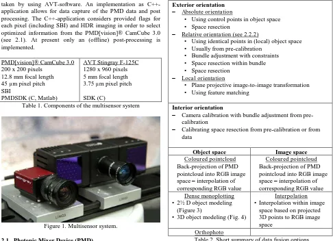
The multisensor system used for the investigations consists of a PMD[vision]® CamCube 3.0 and an Allied Vision Technologies Stingray F-125C camera. Figure 1 shows the fixed arrangement of the used devices as a temporary lab construction. The cameras are mounted side by side and justified with respect to their field of view in order to acquire the targeted scene within an appropriate overlapping area. Due to the different optical parameters of the components (see Table 1) slightly different scenes are observed. The RGB images are taken by using AVT-software. An implementation as C++-application allows for data capture of the PMD data and post processing. The C++-application considers provided flags for each pixel (including SBI) and HDR imaging in order to select optimized information from the PMD[vision]® CamCube 3.0 (see 2.1). At present only an (offline) post-processing is implemented.
PMD[vision]® CamCube 3.0 200 x 200 pixels
12.8 mm focal length 45 µm pixel pitch SBI
PMDSDK (C, Matlab)
AVT Stingray F-125C 1280 x 960 pixels 5 mm focal length 3.75 µm pixel pitch SDK (C)
Table 1. Components of the multisensor system
Figure 1. Multisensor system. 2.1 Photonic Mixer Device (PMD)
A photonic mixer device (PMD) allows for a real-time capture of 3D information. Based on the time-of-flight principle, the phase difference between a transmitted and a received signal is measured. A PMD device can measure the turnaround time of the modulated light, therefore the phase-delay can be determined for each pixel. A phase-shift algorithm, using four shifted samples, is used to calculate the distances between the targeted scene and the camera itself. (Ringbeck and Hagebeuker 2007)
It is well known that the time-of-flight technique is limited in accuracy. The received 3D information is dependent on the correct detection of the emitted light. External influences and object reflectivity cause under- or overexposed pixel information, therefore yielding noise or unquatifiable data.
Usually both effects can be detected considering the amplitude data or checking the individual phase samples (Lindner 2010). Jepping and Wülbern (2012) optimized the distance information of a mixed scene by extracting best information of different data captures with a set of integration times following the principle of high dynamic range imaging (HDR). Furthermore provided flags for each pixel, for example given through a manufacturer's SDK, can be used for the data selection. An additional suppression of background illumination (SBI) helps for selecting the corresponding emitted light.
2.2 3D data fusion processing
2.2.1 Discussion of different options for data fusion Exterior orientation
Absolute orientation
• Using control points in object space • Space resection
Relative orientation (see 2.2.2)
• Using identical points in (local) object space • Usually from pre-calibration
• Bundle adjustment with constraints • Space resection within bundle • Space resection
Local orientation
• Plane projective image-to-image transformation • Using feature matching
Interior orientation
Camera calibration with bundle adjustment from pre-calibration
Calibrating space resection from pre-calibration or from data
Object space Image space
Coloured pointcloud Back-projection of PMD pointcloud into RGB image space – interpolation of corresponding RGB value
Coloured pointcloud Back-projection of PMD pointcloud into RGB image space – interpolation of corresponding RGB value Dense monoplotting
• 2½ D object modeling (Figure 3)
• 3D object modeling (Fig. 4)
Interpolation • Interpolation within image
space based on projected 3D points to RGB image space
Orthophoto
Table 2. Short summary of data fusion options Data fusion processing including interpolation, required for data given by a multisensor solution, can mainly be devided into two approaches a) processing within object space and b) processing within image space. Both approaches require information about the interior and exterior orientation of the systems components. Typically the interior orientation is estimated within a pre-calibration process using, for example, a testfield pre-calibration process. Alternatively, using a calibrating space resection solution the parameters of interior orientation can also be determined if the observed object provides sufficient control point information. For the exterior orientation an absolute, relative or local orientation could be applied. For example, a relative orientation could be estimated from the testfield calibration process too. The determination of interior and exterior orientation depends on the requirements for object
reconstruction and the estimation process itself. While a pre-calibration process offers an independent estimation of the parameters within a controlled adjustment it is also restricted to the field of application. It has to be considered that no changes in construction and optics can be made afterwards. Estimating the parameters from the acquired object data offers the opportunity of flexible data acquisition but typically requires control points. Corresponding points for all processes can be determined by feature matching or by feature measurement, for e.g. signalized points as often used for metrology purposes. For data processing within object space a 2½ D or 3D object modeling based on monoplotting can be applied. Beside a simple coloured pointcloud generation based on the resolution of the surface providing sensor this allows for a dense and coloured pointcloud in object space with respect to the high-resolution image data. An orthophoto resampling allows for a simplified feature extraction in 2D image space and provides corresponding coordinates in object space. The data fusion processing in image space is quite similar. The 3D surface information is back-projected into image space. Subsequent interpolation with respect to the mapped object information is applied to the remaining information in RGB image space. Table 2 gives a short summary on data fusion options to be used for 3D data fusion processing.
2.2.2 Relative Orientation and monoplotting
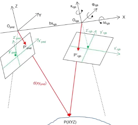
The presented investigation results of the multisensor system are based on a pre-calibration of the interior and exterior respectively the relative orientation parameters (2.3). Figure 2 illustrates the mathematical context of the multisensor system with respect to the object coordinate system. A standard projective imaging approach is used from image space P' (1) to object space P (2) where the perspective centre of the PMD camera Opmd (3) equals the origin in object space, and the perspective centre of the RGB camera Orgb (4) is defined by the system's relative orientation.
Figure 2. Camera and object coordinate system
where z’ = equals calibrated focal length in right order x', y' = image coordinates
X0, Y0, Z0 = coordinates of perspective centre X, Y, Z = coordinates in object coordinate system Monoplotting denotes the process of intersection of a spatial image ray with a given surface, e.g. a digital terrain or surface model (DSM). If an image is absolutely oriented with respect to the DSM each measured image point defines a direction vector pointing onto the surface. In case of 2½ D object models, e.g. given as a regular grid of Z values, the intersecting point can be determined according to Kraus (1997) or Luhmann et al.
Figure 3. Principle of 2½ D monoplotting
The spatial direction defined by the measured image coordinates x', y', z' in the image coordinate system (image vector x') is transformed into the spatial vector X* using the exterior orientation parameters (similarity transform with arbitrary scale, e.g. m = 1). This ray intersects the DSM at point P using a local two Z values of adjacent profile points. Figure 3 illustrates the principle of 2½ D monoplotting.
For the case of real 3D object models, e.g. given by a meshed 3D pointcloud, a different search strategy has to be implemented (Figure 4). Assuming that a TIN model of the surface is available, each triangle of the mesh has to be tested against the image ray. Each triangle consists of three object points P1, P2, P3 forming a plane. The intersection P of the image ray with each triangle plane has to be calculated and tested if it lies inside the triangle. If multiple intersections are given for complex object surfaces, the intersecting point of shortest distance to the camera has to be chosen.
X Z
P'
O
Y
P1
P2 P3
P
TIN
Figure 4. Principle of 3D monoplotting 2.3 System Calibration
The multisensor system, respectively its interior and relative orientation parameters, is calibrated using a testfield calibration method. A set of 23 images was taken with respect to a calibrated testfield (examples in Figure 5). For the time-of-flight camera the intensity image was used, taken with an appropriate integration time to allow for automatic feature measurements of signalized points.
Figure 5. Calibration image for PMD camera (left) and RGB camera (right)
The interior and relative orientation parameters are estimated within a bundle adjustment. Each pair of images provides information for the relative system orientation. A set of ten parameters for the interior orientation is applied to each camera. For radial-symmetric lens distortion the balanced approach is used. Table 3 includes the resulting parameters of interior orientation and its standard deviations. Table 4 shows the results for the relative orientation for the RGB camera of the multisensor system.
Values PMD
Std. deviation
Values RGB
Std. deviation c [mm] 12.4947 0.0019 5.0019 0.0006 x'0 [mm] -0.1091 0.0027 -0.0221 0.0004 y'0 [mm] -0.0996 0.0027 -0.0429 0.0006 A1 -0.0028 1.11e-5 -0.0025 2.54e-5 A2 9.87e-6 7.94e-7 2.65e-4 8.20e-6 A3 -3.32e-8 1.69e-8 -8.32e-6 7.88e-7 B1 2.82e-5 2.27e-6 1.37e-4 5.47e-6 B2 -4.81e-5 2.87e-6 -1.76e-4 7.44e-6 C1 -4.87e-5 2.13e-5 2.58e-4 1.48e-5 C2 -5.51e-4 2.02e-5 -1.90e-4 1.18e-5
R0 [mm] 3.38 1.80
Table 3. Interior orientation parameters and standard deviations
[mm] [radian]
bxrgb 112.0074 ωrgb 0.009455 byrgb -11.4682 φrgb 0.141715 bzrgb -7.0384 κrgb 0.000202 Table 4: Relative orientation parameters for RGB camera
3. DATA FUSION RESULTS
In the following the results of the multisensor data acquisition and 3D data fusion processing will be presented. The results rely on datasets taken by extracting best information of different captures with a set of integration times following the principle of high dynamic range imaging. The camera components have been warmed up for at least one hour to avoid effects within distance measurement (Jepping and Wülbern 2012).
3.1 Accuracy assessment
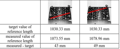
The introduced approach is evaluated with respect to its exterior accuracy using optimized data captures of the testfield as introduced in 2.3. A scale bar is used for the calibration of the testfield. The testfield’s object point accuracy resulted in RMSX = 4.7 µm, RMSY = 3.9 µm and RMSZ = 4.9 µm. The exterior accuracy is estimated using a length taken of the testfield represented by two signalized points (reference length rl) within two positions in the field of view of the multisensor system. The reference length is specified with rl = 1030.3321 mm ± 0.0213 mm. Table 5 illustrates the probing arrangement for the reference length and the verification results. The results are based on a filtered and smooth surface mesh excluding areas outside the reference plane. The type of reference testfield has high impact on the data acquisition of the PMD camera. Due to some protruding points and the signalized points (white dots on black ground) the 3D distance measurements are of low accuracy. In future this could be improved by applying correction models for PMD data.
target value of
reference length 1030.33 mm 1030.33 mm measured value of
reference length 1073.55 mm 1078.96 mm measured - target 43 mm 49 mm
Table 5. Evaluation of exterior accuracy
3.2 Results on footwell test
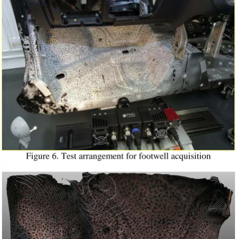
A car body part (footwell) is used in the test arrangement as shown in Figure 6. The surface texture results from former image matching evaluations and provides, for these investigations, the visualization and the user’s orientation. Data post-processing is based on a TIN-model processed with geomagic Studio 2012 and includes data filtering and surface smoothing. The PMD data is chosen from a HDR image processing with integration times from 300 to 1500 µsec. Figure 7 to 9 show the results of data fusion with dense monoplotting.
Figure 6. Test arrangement for footwell acquisition
Figure 7. Result of data fusion and dense monoplotting of a footwell
Figure 8. Coloured point cloud overlayed with dense monoplotting result of a footwell
Figure 9. Orthophoto of footwell scene with ground sample distance of 1 mm
The 3D surface reconstruction is verified with respect to the footwell reference data (stl file) using best-fit analysis in geomagic Studio 2012 (Figure 10). The resulting deviations for the chosen area of interest are within ±30 mm for the major parts. Compared to the exterior accuracy assessment this demonstrates a slightliy better accuracy level. It has to be considered that the data of the footwell scene is of better quality.
Figure 10. Best-fit analysis to reference stl-data
4. CONCLUSION
A multisensor system based on a time-of-flight camera, providing real-time 3D distance information, and a high-resolution RGB camera is a promising approach for close-range applications. Combined with powerful algorithms and appropriate coding it can be applied to the acquisition of dynamic processes. Even using post-processing the multisensor system allows for real-time data acquisition in contrast to laserscanning.
The development of a multisensor system and data fusion processing are presented. Different options on data fusion processing have been evaluated. Finally a pre-calibration of interior and relative orientation for the lab construction of the multisensor system was applied using a testfield calibration approach. Subsequently the acquired data was processed by monoplotting in order to achieve dense and coloured pointclouds. A test arrangement on a car body part (footwell) has demonstrated the potential of the approach. The 3D surface
reconstruction is verified with respect to the footwell reference data using best-fit analysis in geomagic Studio 2012 with deviations of ±30 mm for the major part. Addtionally the exterior accuracy was estimated by using a reference length. The systems exterior accuracy with respect to a discrete length represented by signalized points can be verified to about 50 mm. It has to be considered that the reference object has high impact on the data acquisition of the PMD camera and the 3D distance measurements for this results are of low accuracy. The results demonstrate the potential of this approach. However, the results rely on good distance measurements and therefore the application of correction models for error compensation which have to be implemented. The basic data fusion concept introduced within this paper has been realized successfully and forms the base for further investigations.
5. FURTHER INVESTIGATIONS
One benefit of a combined approach consisting of a time-of-flight camera and a high-resolution RGB camera is its possible use in dynamic processes. With respect to this application the approach will be analysed for implementation within parallel thread coding in order to achieve appropriate framerates. Implementation on GPUs is an additional option. It will be evaluated if real-time data acquisition and processing could be achieved by the given components and data fusion concepts. The data fusion concepts summarized in Table 2 will be analysed for their potential and accuracy. 3D object modeling using monoplotting requires surfaces meshes. A mesh generation and data filtering will be implemented to the C++-application in order to be independent from other software and to allow for possibly real-time processing. It will be evaluated if the consideration of regions of interest for meshes of complex scenes allow for more robust solutions and speed up the object reconstruction.
Data correction models, like suggested by Lindner (2010) or Kahlmann (2007), will be analyzed and applied to the data acquisition and system calibration process. The accuracy for the multisensor system mainly relies on the PMD distance measurements. Suggested optimization, for example including modeling of motion artefacts, minimize distance measurement errors or noise reduction, will be evaluated.
6. REFERENCES
References from Journals:
Huhle, B., Jenke, P., Straßer, W. 2008. On-the-Fly Scene Acquisition with a Handy Multisensor-System. International Journal of Intelligent Systems Technologies and Applications 2008 - Vol. 5, No.3/4 pp. 255 - 263
References from Books:
Kraus, K. 1997. Photogrammetrie, Band 1 - Grundlagen und Standardverfahren.Dümmlerbuch, ISBN 3-427-78646-3 Luhmann, T., Robson, S., Kyle, S., Harley, I. 2006. Close Range Photogrammetry, Principles, Methods and Applications, Whittles Publishing, ISBN 1-870325-50-8
References from Other Literature:
Abdelhafiz, A. 2009. Integrating Digital Photogrammetry and Terrestrial Laser Scanning. Deutsche Geodätische Kommission, Dissertationen, Reihe C, No. 631.
Bartczak, B., Schiller, I., Beder, C., Koch, R. 2008. Integration of a Time-of-Flight Camera into a Mixed Reality System for Handling Dynamic Scenes, Moving Viewpoints and Occlusions in Real-Time. In: Proceedings of 3DPTV’08 – the Fourth International Symposium on 3D Data Processing, Visualization and Transmission, Paris, France.
Boehm, J., Pattinson, T. 2010. Accuracy of exterior orientation for a range camera. In: International Archives of Photogrammetry, Remote Sensing and Spatial Information Sciences, Vol. XXXVIII, Part 5, Commission V Symposium, Newcastle upon Tyne, UK.
Fuchs, S., May, S., 2007. Calibration and Registration for Precise Surface Reconstruction with TOF Cameras. In: Proceedings of the Dynamic 3D Imaging Workshop in Conjunction with DAGM (Dyn3D) (Heidelberg, Germany, September 2007), vol. I.
Jepping, C., Wülbern, C. 2012. Untersuchungen zum Genauigkeitspotential und Anwendungsbereich einer 3D TOF-Kamera. In: Photogrammetrie-Laserscanning-Optische 3D-Messtechnik, Beiträge der Oldenburger 2D-Tage 2012, Wichmann.
Kahlmann, T. 2007. Range Imaging Metrology: Investigation, Calibration and Development. Dissertation ETH No. 17392. Lindner, M., Kolb, A., Hartmann, K. 2007. Data-Fusion of PMD-Based Distance-Information and High-Resolution RGB-Images. Signals, Circuits and Systems, 2007. ISSCS 2007. International Symposium on , vol.1, no., pp.1-4
Lindner, M. 2010. Calibration and Real-Time Processing of Time-of-Flight Range Data. Dissertation Universität Siegen. Ressl, C., Haring, A., Briese, Ch., Rottensteiner, F. 2006. A concept for adaptive mono-plotting using images and laserscanner data. In: International Archives of Photogrammetry, Remote Sensing and Spatial Information Sciences, Vol. XXXVI, Part 4, Commission III Symposium, Bonn, Germany.
Reulke, R. 2006. Combination of distance data with high resolution images. In: International Archives of Photogrammetry, Remote Sensing and Spatial Information Sciences, Vol. XXXVI, Part 5, Commission V Symposium, Dresden, Germany.
Ringbeck, Th., Hagebeuker, B. 2007. A 3D time of flight camera for object detection. In: Optical 3-D Measurement Techniques VIII (Eds.: Grün, Kahmen), Zurich.
Schwermann, R., Effkemann, C. 2002. Kombiniertes Monoplotting in Laserscanner- und Bilddaten mit PHIDIAS. In: Photogrammetrie und Laserscanning – Anwendung für As-Built-Dokumentation und Facility Management, Wichmann, pp. 57-70
Van den Bergh, M., Van Gool, L. 2011. Combining RGB and ToF cameras for real-time 3D hand gesture interaction. Applications of Computer Vision (WACV), 2011 IEEE Workshop on, pp.66-72