ELECTRICAL LOAD WITH THIS VOLTAGE
by Emilian Ceuca
Abstract: Current and new commercial products at 14 VDC must be integrated into a 42 VDC automotive bus system. The challenge is to find and implement the best and most reliable, cost-effective technology. Energy efficiency is also a key factor. This paper will investigate a variety of technologies and begin to develop at least one for practical use. Possible technologies include DC/DC converters, optical couplers, and pulse width modulation (PWM). Smart power techniques like current limiting may be investigated as a possible lower cost alternative to DC/DC converters. Redesign of the commercial load is also an alternative.
1. LIGHTING AND THE ELECTRICAL SYSTEM
A standard car uses a couple hundred watts of power on lighting. The headlights themselves consume 55 watts each. The basic lighting circuit of a vehicle starts at the voltage regulator, taking the AC voltage of the alternator and turning it to DC or at the battery. At this point it goes to the fuse box and branches into different parts. A fuse will typically have several items running through it, including several lights and small motors. The set of lights running through a car are basically the same.
Switches in the vehicle can run in several different manners. They can simply turn on or off a set of lights. They can only turn on if both switches are on and etc. Cars now have lights that turn on when it’s dark and stay on for a few seconds after the car is turned off.
Most of the cars are running on the 14-V system. However, with more electrical components installed in the automobiles, more and more power will be needed. Thus, the 42-V system was proposed to replace the current 14-V system. The only difference is instead of using one 12-V battery1, the 42-V system requires a 36- V battery. Eventually, a single 36-V battery will replace the current 12-V battery. But for our purposes, we will stick to three 12-V batteries connected in series since the “proposed” 36-V battery has not been fully developed yet.
Below are some of the electrical systems that the 42-V system will power:
1
The standard automotive battery in current vehicles is 12 volts. Each battery has six cells with 2.1 volts each. A car battery is considered to be fully charged at a voltage of 12.6 volts.
¾ Engine
¾ Power Window
¾ Power Locks
¾ Power Mirrors
¾ Power Seats
¾ Electric brakes and steering
2. SPECIFICATIONS AND CONSTRAINTS
As design started, the problem is to develop a system for reducing the voltage to appropriate levels. These levels are determined by the device to be operated by the system. The devices that we will be powering range from lights, door lock actuators, to automatic seat adjusters. The voltages that we need to supply are usually around 12 to 14 volts and only for a small period of time, except in the case of the lights. Our system will see a maximum operating voltage, produced by the generator, of 48 volts with a maximum ripple of 2 volts. Thus the maximum voltage that our system must handle is 50 volts. However, in the case of transient voltages, or load dumps, we may see a voltage of up to 58 volts (for approximately 400 ms). The minimum voltages that our system will need to handle are found when the engine, and thus the generator, is off. These voltages would be approximately 36 volts and are produced by the battery.
Other constraints that we have come up with for our part of the project are as follows:
¾ The system needs to be relatively small in order to be able to fit into the automobile.
¾ Multiple systems will need to be installed in the automobile so that if one of the systems is damaged or fails then the entire vehicle will not be affected.
¾ We need to make the system relatively inexpensive or to incorporate it into an existing system in order to minimize cost. (This includes mass production costs and retooling of existing assembly plants)
¾ The system must not produce too much heat so as not to require a large heat sink.
¾ The system must be able to operate in a range of environmental conditions (humidity, temperature, vibration, etc)
¾ The system must have a reasonable lifetime. 3. SOLUTIONS
3.1 Pulse Width Modulation
Pulse width modulation (PWM) is a means of converting a given input voltage to a lesser output voltage using pulses of a specified duty cycle and frequency. Advantages
¾ Low Power Dissipation (Heat)
¾ Very Reliable
¾ Timer or Micro-controller Operated
Disadvantages
¾ High Cost
The duty cycle is defined as the ratio of the time-on to the period of a waveform. In order to convert a 42-volt bus to a 14-volt bus a theoretical duty cycle of 11.1 % is necessary. Equation 1.1 shows how to calculate the rms value of a voltage.
∫
The desired theoretical duty cycle is easily found by squaring both sides, substituting the given values for vin and vrms, and integrating over the time the input voltage is on.
%
Although this duty cycle is sufficient in theory, switching losses and losses due to the resistance in wires causes a demand for a larger duty cycle. The frequency of the PWM signal is another concern with respect to efficiency and EMI. The ability of a specific motor or light rated at 14V to work with PWM at 42V is also a major question. Testing will be done to address these concerns and choose the most efficient duty cycle and frequency of the PWM. However the unavailability of test equipment that measures the EMI of a circuit will leave some questions unanswered.
3.2 Software Description
The software developed for a Motorola M68HC11E9 micro-controller outputs a PWM train with a configurable duty cycle and frequency. The internal TCNT counter is used along with the output compare functions to control bits 3-6 of port A. Because the output compare functions can run on interrupts this software can easily be implemented into an existing micro-controller, therefore making this a cost-effective solution.
The internal TCNT counter is a 16 bit upward counter in the HC11 therefore counting from 0h0000 to 0hFFFF. The rate at which the unsigned counter is incremented depends on two bits in the TMSK2 register, which configures a prescale factor.
The sole functionality of configuring the pre-scale factor in this design is to decrease the minimum possible frequency of the PWM.
detected. The OC1 output compare can directly control pins 3-7 of port A, while each other output compare can control one output of port A according with the following relationships: OC2/PA6, OC3/PA5, OC4/PA4, OC5/PA3. Therefore pins 3-6 can be directly controlled by two different output compares. In addition to this, interrupt service routines can also control output pins increasing the flexibility of the output-compare functions.
There are two working assembly language programs, each with their own advantages and disadvantages. The first uses a simple approach with programmable frequencies and possible duty cycles ranging from 0-100%. The second, although more complex, may produce less EMI and ripple on the input voltage. (need to prove this!!!!) There are limitations on the duty cycle and frequency of PWM for the second program.
The first program uses all of the output compare functions to directly control pins 3-6 of port A. Upon initialization, the two output-compares, OC1 and OC2, are configured to generate interrupts. OC2-OC5 are then enabled to set their respective output pins high on a successful compare, while OC1 will set them all low on a match. As a result of this configuration, pins 3-6 of port A will all set and clear simultaneously with each other. The interrupts generated from OC1 and OC2 clear the flags set by the successful compare. In addition, each output compare’s register is incremented to create the next period of the waveform. The variables frequency and duty control the frequency and duty cycle of the program. In order to change the frequency or duty cycle of the program, the code has to be modified accordingly. The equations that relate the actual frequency and duty to their variables are shown below.
f
Figure 1: Program 1 Output
Obviously the duty cycle in the figure above is not accurate. Factors such as rise and fall times, and the free running quality of the TCNT timer lead to these inaccuracies. After testing is done on the lights and motors, the program will be calibrated to the most efficient frequency and duty cycle using an oscilloscope. In theory the program can be used for frequencies ranging from 2 Hz to 250 kHz for the duty cycle needed for this application. After testing, the actual limitations on the frequency will be determined.
The second program also uses the TCNT counter and output compare functions to generate a pulse train. In this program however, the pulses rise and fall at separate times over a given period. In order to accomplish this all of the output compares are configured to generate interrupts. When output compares OC2-OC5 occur, their specific pin is set high and the next interrupt in line is set up for a quarter of the period later. The flag is then cleared and a return is issued. When an OC1 interrupt occurs all pins are set low, its register is incremented by a quarter of the period, the flag is cleared, and control is returned to the main program. Since the value of a quarter of the period is used so often the second program has another variable called quarter. The defining equation is simple but it saves 41 E-clocks necessary to complete a division instruction on the HC11:
4
variable
f
quarter= (1.5)
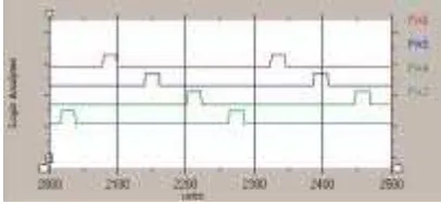
The output for this program at 5 kHz and a duty cycle of 12.5% is shown in Figure 2 below:
Figure 2: Program 2 Output
which would have an negative impact on the input voltage and EMI. The second approach decreases the magnitude of the instantaneous load change on the power supply.
3*12 V BATTERY (36 V)
Installing three 12- volt batteries, or one 36-volt and one 12-volt would make it possible to power the 12 volt loads. This would add a lot of extra weight to the vehicle, in the actual batteries and also in the generators needed to re-charge them. Having more batteries to take up more room would require harder access to them and make it more difficult to work on. It would also provide more chances for components to break.
When a battery drops voltage, even by a small amount, it makes a big difference. For instance, when a battery drops from 12.6 to 12.0 volts,
its power drops from 100 to 25%. At 12.4 volts, a car battery is 75% charged. At 12.2 volts, it's 50% charged. A car battery is considered charged at 12.4 volts or higher. It is considered discharged when it's at 12.39 volts or less.
To achieve the chemical reaction that creates voltage in an automotive battery, the electrolyte solution inside the battery must have the correct mixture of water and sulfuric acid. When a car battery is at a voltage of 12.6 volts, it is charged at 100 percent. At 12.6 volts, the electrolyte solution is 65
percent water and 35 percent sulfuric acid, which is considered to be the ideal combination.
Cold Cranking Amps (CCA) is critical for good cranking ability. It refers to the number of amps a battery can support for 30 seconds at 0°F until the battery voltage drops to unusable levels. For example, a 12 volt battery with 600 CCAs means the battery will provide 600 amps for 30 seconds at 0°F before the voltage falls to 7.20 volts (six cells). The higher the CCA, the more powerful the cranking ability.
Currently, we do not need to use a specific car battery, and any ordinary car battery will be able to work in this project. Ford uses a specific type of battery for their cars and trucks, such as BXT65 Battery (7 1/4 " x 11 1/4") for all trucks. Typical cost of this battery is around $100.
3.3 Voltage Divider
Advantages
¾ Low Cost
¾ Easily Implemented Disadvantages
¾ Short Lifetime High
¾ Power Dissipation (Heat)
¾ Multiple Parts for Each Device
1. The current flows through 2 resistors
The circuit is consists of a voltage source, R1 and R2. The resisters are in series. We can calculate the current through the circuit using ohm’s law.
Ex.) Let V=36V, R1= 5 ohms and R2=10 ohms I = 36 / (5 + 10) = 2.4 A
2. Voltage drop due to the current
The current will produce a voltage drop across the resistors depending on the resistor values.
According to the previous example, you will get 24 V across R2 (V2= 2.4 * 10), and 12 V across R1 (V1 = 2.4 * 5). The sum of the voltages is 36 V. The power, which the two resistors convert to heat, is also divided. R1 is heated by 2.4 * 12 =28.8 W and R2 is heated by
2.4 * 24 = 57.6 W. Total = 86.4W (Pt = 36 * 2.4) 3. Inner resistance
Here is a voltage source drawn. It has an inner resistance. The load resistor RL does not get the whole voltage of the battery at the
terminals, because a part is lost in the inner resistance Ri of the battery. The same applies to a generator and a transformer and so on.
Let V=36 V and Ri = 1 ohm
RL (ohms) I VL Pi PL
100 0.356A 35.6V 126.74 mW 12.67W
80 0.444A 35.52V 197.14 mW 15.77W
50 0.706A 35.3V 498.44 mW 24.92W
10 3.273A 32.73V 10.7W 107.13W
5 6A 30V 36W 180W
1 18A 18V 324W 324W
0.5 24A 12V 576W 288W
0 36A 0V 1296W 0W
When the load is 100 ohms, the voltage at the terminals of the voltage source is almost equal to the no-load voltage, but with the 5 ohms load the terminal voltage drops down to 30V. The power drawn from the source is 180W but the battery itself is heated with 36W power loss.With decreasing load not only the current and the load power increases, but also the power losses rise enormously. With a 1 ohm load resistor the terminal voltage decreases to one half and the power losses are equal to the load power. With even further decreased load resistance the power losses grow extremely high, but the load power decreases!
So, the Maximum power when you load with a resistance value that is equal to the source resistance.
3.4 Voltage Regulator
The voltage regulator should be a very effective way to generate the needed voltages. There are several different ways to do this and many different regulators that could accomplish.
¾ High Power Dissipation (Heat)
Choose the following values for optimization: VREF = 1.23 V
CIN = 470 µF COUT = 220 µF
L1 = 68 µH R1 = 1 kΩ VOUT = 12.8 V
2 3
10
31
1
R
C
FF×
×
=
After calculations, R2 = 9.406 kΩ and CFF = 3.43 X 10⁻⁹ F.
The problem with the voltage regulator is, however, the dissipation of power. We will, in some cases, be dropping the voltage from 42 volts down to 12 volts. That means that 30 volts will effectively have to be dissipated. This energy will be in the form of heat and would require a rather large heat sink in order to properly dissipate the generated heat. Thus the design is deemed unfeasible because of the size and difficulty in installing and situating the system in the automobile.
3.5 Lighting Alternatives
Different sources of Lighting are also another solution. One possible solution is the use of LED’s.
Advantages
¾ Power Saving Disadvantages
¾ High Cost
¾ No White
¾ Not Bright Enough
¾ Not Reliable over Time
Different sources of Lighting are also another solution. One possible solution is the use of LED’s. Some high mount stoplights use red LED’s. The inability to produce pure white LED’s is a barrier though. Several different colored LED’s can be combined together in a bunch to produce a white like light but this isn’t efficient and people with color- deficient vision have problems with this ‘white’ light. LED’s are solid state semi-conductor devices that convert electrical energy into light. LED “cold” generation of light leads to high efficacy because most of the energy radiates within the visible spectrum.” (Lighting Futures “LEDs: From Indicators to Illumination)
One alternative design to power 14-volt loads from a 42-volt bus involves the use of a DC/DC converter. A DC/DC converter first takes an input voltage and converts it to an AC voltage.
Advantages
¾ Easily Implemented
¾ Low Ripple
¾ Programmable Output
Disadvantages
¾ High Cost
¾ Under Development
A DC/DC converter first takes an input voltage and converts it to an AC voltage. After the conversion the voltage is transformed and rectified to the desired DC output voltage. DC/DC converters possess numerous advantageous physical qualities for use in automobiles where issues like space and weight arise. They are small, lightweight, silent, and have no moving parts. Electrically, they are a high power, efficient, low noise, and reliable power supply. A VI-200 model made by Vicor has a maximum output power of 200 W and efficiencies ranging from 80-90%. This DC/DC converter also features wide input voltage ranges, output programmability, output over voltage protection, and thermal shutdown. The main disadvantage of DC/DC converters is their cost, which is a major concern for mass produced automobiles where a small change in the price for one unit can mean millions of dollars. Despite their high expected cost of about $0.10 per Watt of power, DC/DC converters will be necessary to power loads that are constantly running like stereos, gauges, and other various convenience features. The challenge is to reduce the cost by powering the lighting system and loads that run in short spans such as door lock actuators, power windows, and power locks in an alternative way.
REFERENCES
[1] Kassakian, J. G., H. C. Wolf, J. M. Miller and C. J. Hurton, “Automotive Electrical Systems circa 2005,” IEEE Spectrum, Aug. 1996, pp. 22- 27.
[2] Miller, J.M., et al., “Making the Case for a Next Generation Automotive Electrical System” IEEE-SAE International Congress on Transportation Electronics (Convergence), Dearborn, MI, Oct. 1998.
[3] Review of the Research Program of the Partnership for a New Generation of Vehicles, Fifth Report, National Research Council, National Academy Press, 1999. [4] “Automobile Industry Association Expects Production of Fuel-Efficient Cars to Begin by 2000,” The Week in Germany, German Information Center, NY, Sept. 15, 1995, p. 4.
[5] Terry, S.M., “12 Volts Presents Its Case,” SAE Journal, Feb. 1954, p.29.
[7] http://auto.mit.edu/consortium/
[8] “Electric Power Steering Coming to Europe,” The Hansen Report on Automotive Electronics, vol. 9, no. 8, Oct. 1996.
[9] “Camless BMW Engine Still Faces Hurdles,” Automotive Industry (AI), Oct. 1999, p. 34
[10] F. Pischinger et. al., “Electromagnetically Operating Actuator,” US Patent no. 4,455,543, June 19, 1984.
[11] “In gridlock’s grip: L.A. stuck at No. 1,” USA Today, Nov. 17, 1999.
[12] Graf, A., D. Vogel, J. Gantioler and F. Klotz, “Intelligent Power Semi-conductors for Future Automotive Electrical Systems,” 17 th Meeting Electronik im Kraftfahrzeug, VDA, Munich, June 1997.
[13] Coutts, Timothy J. and M. C. Fitzgerald, “Thermophotovoltaics,” Scientific American, September 1998 .
Author: