SCIENTIFIC PAPER
Arranged as One of Requirement to Finish The Bachelor (S1) at Department of Electrical Engineering Faculty of Engineering
Universitas Muhammadiyah Surakarta
Submitted by:
Dhucha Ajitama
D 400 112 002
DEPARTMENT OF ELECTRICAL FACULTY ENGINEERING
UNIVERSITAS MUHAMMADIYAH SURAKARTA
TRAFFIC LIGHT CONTROL USING FPGA
Dhucha Ajitama
Department of Electrical Faculty Engineering Universitas Muhammadiyah Surakarta
Email : [email protected]
ABSTRAC
In this study made a simulation of traffic lights by using a FPGA module. Traffic lights are to regulate traffic lights installed at the intersection of highways is useful to regulate road users, in order to run according to the rules and not a traffic accident. Traffic lights will be connected using IDC 40 pin cable to the GP I / O. Simulations were designed in this study using two types that exist in the FPGA. The design simulation using VHDL language, then updated to the Function Block Diagram (BDF). BDF used as a top-level Entity or as the center of the whole system. BDF consist of 2, namely: a traffic light system (traffic) and system clock devider (clk_div). Traffic light system has two types that could run in the BDF, the traffic light system 2-way crossing pedestrians using the button (type 1) and 4-way type using buttons pedestrian crossings (type 2). Traffic light system type 1 has 8 pieces of state. Then the lights started from the North-South direction is green for 5 seconds, then to yellow for 1 second, afterwards became all red for 1 second and then will move to the West-East into a green light. When the pedestrian button is pressed, the pedestrian light is green for 6 seconds and the main road to red lights all. Pedestrian lights made longer useful to anticipate pedestrians crossing or crossing diagonally. The traffic light type 2 will begin with a traffic light next to the North colored green for 5 seconds, then to yellow for 1 second, after it became red for 1 second and move to the hand of the West with the provisions of the same time and rotating clockwise. Transfer traffic light system is controlled by the displacement function keys consisting of: d, d1, and clr. The system clock divider is useful for controlling the switching time from one to the other state. Traffic lights get a clock of 5.7220 Hz
Keyword: FPGA VHDL, traffic light, BDF 1. Preliminary
Traffic light technology in Indonesia continues to grow. Besides having a role in regulating the density of traffic on the highway it also enhances traffic safety. Every major intersection in Indonesia
be designed and simulated using fuzzy logic-based Microcontroller (Taufik, Supriyono, Sukarman, 2008). Microcontrol is a computer chip which consists of several microprocessors and has a special function (Ganiyu, Arulogun, Okediran, 2014).
Microcontroller has the advantage that it has small size and only has special functions depending on the program that is inputted by programmer in the object. Besides the advantages, there are also weaknesses of the microcontroller, which needs a lot of contactors to enable traffic lights to be switched on. In the development, a system that only requires fewer contactors by using the PLC was created. PLC is a special program of industrial control (ladder diagram) that is useful to monitor and control industrial processes and are designed to withstand industrial environments and is resistant to interference (noise, vibration, shock, temperature, himidity) (Indrawan, Haritman, Hakim, 2013).
Another system used is the FPGA, which is connected between the gate array rows and columns that can be programmed by using the computer connected with USB. There are advantages when using an FPGA which can redesign components without the need to buy a new processor, operated in parallel, and has a large capacity RAM for
data storage. In establishing the design of FPGA, there are many ways that can be done, one of which is by using a block diagram or using VHDL data script. Microcontroller and PLC system are well known to students of Electrical Engineering University of Muhammadiyah Surakarta (UMS), but FPGA is a new thing that is still studied by students. Besides, there are some students that make prototype experiment using PLC or by a microcontroller. Therefore this study is a new innovation that is manufacturing of traffic lights using FPGA system with VHDL language.
2. The research method 2.1.Requirement Analysis
pedestrians which is useful as a tool for crossing pedestrians and present in all lanes
2.2.Design
2.2.1. Crossing Line Design
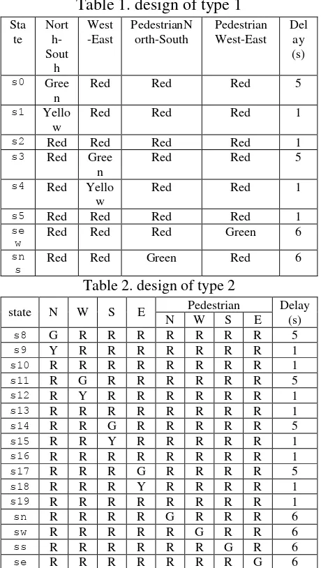
Crossing Track Design have two types, namely: 2-way crossings with pedestrian (type 1) and 4 directions crossing with pedestrian (type 2). For type 1 can be describe in Table 1 and type 2 describe in Table transfer the desired functions, namely: d, d1, and clr. Function keys are placed on FPGA board. The function buttons are described below:
1) If no key is pressed, the type 1 would work on line crossings.
2) If the button clr = 1, the light will stop and return to its initial state.
3) If button d = 1, the light will blink yellow.
4) If button d and d1 is 1, the crossings will turn into type 2.
2.3.Detail of design
and traffic light system begins with using VHDL and then update to BDF. Top-level BDF figure can be seen in Figure 1.
Figure 1. BDF (Block Diagram Function)
For a traffic light system type 1 or two crossing with pedestrian button can be explained by the State Diagram shown in Figure 2.
Figure 2 state diagram type 1
Figure 2 can explain at bellow
1. When s0
Running until 5 second (North-South are green, West-East are red).
If the input is 00011 and time 5 second is over, change to state s1.
2. When s1
Running until 1 second (North-South are yellow, West-East are red).
If the input is 00011 and time 1 second is over, change to state s2.
Another if input is 00001 and time 1 second is over, change to state sns.
3. When s2
Running until 1 second (all reds).
If the input is 00011 and time 1 second is over, change to state s3.
4. When s3
Running until 5 second (North-South are red, West-East are green).
If the input is 00011 and time 5 second is over, change to state s4.
5. When s4
Running until 1 second (North-South are red, West-East are yellow).
If the input is 00011 and time 1 second is over, change to state s5.
Another if the input is 00010 and time 1 second is over, change to state sew.
6. When s5
Running until 1 second (all reds).
If the input is 00011 and time 5 second is over, change to state s0.
7. When sns
Running until 6 second (North-South pedestrian are green and main road all reds).
If the input 00011 and time 6 second is over, change to state s3.
Running until 6 second (West-East pedestrian are green and main road all reds) If the input 00011 and time 6
second is over, change to state s0
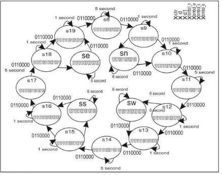
For a traffic light system type 2 or four crossing with pedestrian button can be explained by the State Diagram shown in Figure 3
Figure 3. State diagram for type 2 Change of state can explained in bellow:
1. When s8
Running until 5 second (North is green and other red).
If the input is 011 and time 5 second is over, change to state s9.
2. When s9
Running until 1 second (North is yellow and other red)
If the input is 011 and time 1 second is over, change to state s10.
if input 0110111 and time 1 second is over, change to state sn.
3. When s10
Running until 1 second (all lights are red).
If the input is 011 and time 1 second is over, change to state s11
4. When s11
Running until 5 second (West is green and other red).
If the input is 011 and time 5 second is over, change to state s12.
5. When s12
Running until 1 second (West is yellow and other red)
If the input is 011 and time 1 second is over, change to state s13
if input 0111011 and time 1 second is over, change to state sw.
6. When s13
Running until 1 second (all lights are red).
If the input is 011 and time 1 second is over, change to state s14.
7. When s14
Running until 5 second (South is green and other red).
If the input is 011 and time 5 second is over, change to state s15.
if input 0111101 and time 1 second is over, change to state ss.
8. When s15
Running until 1 second (South is yellow and other red)
If the input is 011 and time 1 second is over, change to state s16.
9. When s16
Running until 1 second (all lights are red)
If the input is 011 and time 5 second is over, change to state s17.
Running until 5 second (East is green and other red).
If the input is 011 and time 5 second is over, change to state s18.
if input 0111110 and time 1 second is over, change to state se.
11.When s18
Running until 5 second (East is yellow and other red).
If the input is 011 and time 5 second is over, change to state s19.
12.When s19
Running until 5 second (all lights are red).
If the input is 011 and time 5 second is over, change to state s8.
13.When sn
Running until 6 second (North pedestrian are green and main
Running until 6 second (South pedestrian are green and main
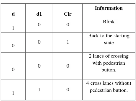
The traffic light type 2 will run if the input to the clr, d, and d1 are „011‟. Then, traffic light will run start from state s8 to s19 with on the rule. First traffic light is green I the North and other are reds and rotate clockwise.Design of the button have 3 buttons and has 4 functions to changing, namely: d, d1, and clr described at Table 3
Table 3. The button function
d d1 Clr
Information
1 0 0
Blink
0 0 1
Back to the starting state
0 0 0
2 lanes of crossing with pedestrian
button.
1 1 0
4 cross lanes without pedestrian button.
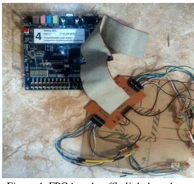
3. The Result
Figure 4. FPGA and traffic light board
3.1.Testing and Analysis
3.1.1. Testing traffic light board and LED
The total number of LED are 20 and are connected to the testing board made by the researcher. From the testing board, the LED are then connected by IDC cable 40 pins to I/O FPGA board. The LED will be turn on started from North then rotate by clockwise direction, with fixed timer.
3.1.2. Testing of delay of traffic light time state
The testing of time state is from Green to Yellow and then to Red. After that, the testing is made to the exchange from North to West until North again by clock direction as a result of the clock from FPGA system that is programmed for organizeing the timer. Clock divider used has 23. This clock produced frequency. So, the frequency arrangement is explained through this equation (1) then the value is put into equation (2) to get the time value needed.
⁄ ……….(2)
The time state of the LED work from one to the other is shown at Table 4 for type 1 or intersection with 2 direction and pedestrian button.
Table 4. 1 Intersection with 2 lines using pedestrian buttons for crossings
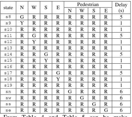
Stat intersection with four pedestrian lanes for crossings with pedestrian button.
Table 5 The model of the intersection with four pedestrian lanes for crossings with
state N W S E Pedestrian Delay simulation wave form can show in Figure 5
Figure 5 Simulation wave
3.1.3. Testing the function keys
Prototypeof traffic light has three key functions and have 4 function in the form of d, d1, and clr. If the button is worth1 or 0, it will have a predetermined function, namely: blink, 2 lanes crossing use pedestrian button, 4-lane pedestrian crossings with button, turn back to the beginning, and blinking mode.
Function keys can be seen in Table 6
Table 6. Function Key
d d1 Clr Keterangan
1 0 0 Blink
0 0 1
Back to thestarting state
0 0 0
2 lanes of crossing with pedestrian
button.
1 1 0
4 cross lanes with pedestrian button.
4. Conclusion
1. The traffic light is designed by using Very High Speed Integrated Circuit “VHSIC” High Description Language (VHDL) that can be updated to Block Diagram Function (BDF).
2. Traffic lights type 1 are controlled by 5 inputs and traffic lights type 2 controlled by 7 input
3. Switching button function are controlled by input, namely: d, d1, and clr
4. The time delay depends on the clock programmed.
5. References
Indrawan, Irvan, etc, 2013, Pembuatan Antarmuka Mesin Manusia Pada Modul Latih PLC Berbasih Perangkat Lunak CX Designer, Electrans, Bandung: FPTK Universitas Pendidikan Indonesia, Vol 12, No 2, Hal 97-106.