[21] L. Hunsberger, “Algorithms for a temporal decoupling problem in multi-agent planning,” inProc. Amer. Assoc. Artif. Intell., 2002, pp. 468–475. [22] L. Hunsberger, “Group decision making and temporal reasoning” Ph.D.
dissertation, Harvard Univ., Cambridge, MA, 2002.
[23] L. R. Planken, M. M. de Weerdt, and C. Witteveen, “Optimal temporal decoupling in multiagent systems,” inProc. 9th Int. Conf. Autonom. Agents Multiagent Syst., Toronto, ON, Canada, May 2010, pp. 789–796. [24] S. Karaman, M. Faied, E. Fazzoli, and A. Girard, “Specification and
plan-ning of interactive UAV missions in adversarial environments,” presented at the AIAA Guid., Navigat., Control Conf., Chicago, IL, Aug. 2009. [25] S. Minton, M. Johnston, A. Philips, and P. Laird, “Solving large-scale
constraint satisfaction and scheduling problems using a heuristic repair method,” inProc. Assoc. Adv. Artif. Intell., Washington, DC, May 1990, pp. 17–24.
[26] M. Yokoo, “Asynchronous weak-commitment search for solving dis-tributed constraint satisfaction problems,”Lecture Notes Comput. Sci., vol. 976, pp. 88–102, 1995.
[27] M. Yokoo, E. H. Durfee, I. Ishida, and K. Kuwabara, “Distributed con-straint satisfaction for formalizing distributed problem solving,” inProc. IEEE Int. Conf. Distrib. Syst., Jun. 1992, pp. 614–621.
[28] S. Russell and P. Norvig,Artificial Intelligence. Upper Saddle River, NJ: Prentice–Hall, 2010.
[29] J. Jackson, M. Faied, P. Kabamba, and A. Girard, “Communication-constrained distributed task assignment,” Univ. Michigan, Ann Arbor, Tech. Rep., 2011.
[30] P. J. Modi, W. M. Shen, M. Tambe, and M. Yokoo, “An asynchronous complete method for distributed constraint optimization,” inProc. Second Int. Conf. Autonomous Agents Multiagent Syst., 2003, vol. 14, no. 18, pp. 161–168.
[31] R. Mailler and V. Lesser, “Asynchronous partial overlay: A new algorithm for solving distributed constraint satisfaction problems,”J. Artif. Intell. Res., vol. 25, pp. 529–576, Apr. 2006.
Dead Reckoning in a Dynamic Quadruped Robot Based on Multimodal Proprioceptive Sensory Information
Michal Reinstein and Matej Hoffmann
Abstract—It is an important ability for any mobile robot to be able to
estimate its posture and to gauge the distance it traveled. In this paper, we have addressed this problem in a dynamic quadruped robot by combin-ing traditional state estimation methods with machine learncombin-ing. We have designed and implemented a navigation algorithm for full body state (po-sition, velocity, and attitude) estimation that uses no external reference but relies on multimodal proprioceptive sensory information only. The ex-tended Kalman filter (EKF) was used to provide error estimation and data fusion from two independent sources of information: 1) strapdown mech-anization algorithm processing raw inertial data and 2) legged odometry.
Manuscript received May 10, 2012; revised October 22, 2012; accepted November 9, 2012. Date of publication December 5, 2012; date of current ver-sion April 1, 2013. This paper was recommended for publication by Associate Editor A. Ijspeert and Editor D. Fox upon evaluation of the reviewers’ com-ments. The work of M. Reinstein was supported by the Project FP7-ICT-247870 NIFTi. The work of M. Hoffmann was supported by the Project FP7-ICT-270212 “eSMCs.” The material in this paper was presented in part at the 2011 IEEE International Conference on Robotics and Automation.
M. Reinstein is with the Department of Cybernetics, Center for Machine Perception, Faculty of Electrical Engineering, Czech Technical University in Prague, Prague 166 27, Czech Republic (e-mail: [email protected]). M. Hoffmann is with the Artificial Intelligence Laboratory, University of Zurich, 8050 Zurich, Switzerland (e-mail: [email protected]).
This paper has supplementary downloadable material available at http://ieeexplore.ieee.org.
Color versions of one or more of the figures in this paper are available online at http://ieeexplore.ieee.org.
Digital Object Identifier 10.1109/TRO.2012.2228309
We have devised a novel legged odometer that combines information from a multimodal combination of sensors (joint and pressure). We have shown our method to work for a dynamic turning gait, and we have also success-fully demonstrated how it generalizes to different velocities and terrains. Furthermore, our solution proved to be immune to substantial slippage of the robot’s feet.
Index Terms—Dead reckoning, extended Kalman filter (EKF), legged
robots, odometry, path integration, slippage.
I. INTRODUCTION
It is a strong requirement for any mobile agent, either animal or robot, to be able to estimate its posture and to gauge the distance it traveled. The former is usually crucial for successful locomotion; the latter for navigation. The information can be—often indirectly—obtained from various sensors: proprioceptive (inertial measurements, joint sensors on legs, or motor encoders) and exteroceptive (primarily visual infor-mation and compass measurements). Exteroceptive sensors—which acquire information from the robot’s environment—can be also used to perceive external references (landmark detection using visual sensors, for instance) that are necessary for long-term precision in a navigation task.
In mobile robots, a popular solution lies in the combination of a proprioceptive component in the form of an inertial navigation system (INS) and an external reference system. The INS combines information from accelerometers and gyroscopes composed in an inertial measure-ment unit (IMU) and integrates them into relative changes of the robot’s pose. If long-term precision is to be guaranteed, absolute information needs to be provided. External references (landmarks) can be sensed using vision (see, e.g., [1]) or ultrasonic sensors [2], or absolute posi-tion informaposi-tion can be directly obtained from a GPS (see, e.g., [3]). However, all these solutions have limitations. For instance, signal ro-bustness, availability (indoor/outdoor), and accuracy issues (attenu-ation through atmosphere, multipath errors) can be listed among the drawbacks of a GPS; computer vision has typically high computational requirements and is vulnerable to lighting conditions and the presence and saliency of landmarks in the environment.
Inspired by the animal kingdom, in this paper, we aim to solve the classical dead reckoning (path integration) problem by proposing a system that does not rely on any external reference. Studies on mam-mals and arthropods (see, e.g., [4]–[6]) have accumulated evidence that motion and position can be reliably estimated relying on the so-called self-motion cues (such as inertial and joint information) only. Since neither absolute position nor heading can be sensed directly, drift is eventually inevitable. The challenge lies in achieving a graceful degra-dation of the estimates.
In our mobile robot, we have decided to use a low-cost IMU as our primary sensor. However, to prevent a major drift in estimates that would result from double integration of raw noisy inertial data, we were seeking another information source (other than external refer-ence) that would provide aiding. In general, there are two possibilities. First, a kinematic model of a vehicle can be used, typically to provide velocity constraints. Second, aiding information can be provided by an additional ego-motion sensor: an odometer.
In wheeled robots, the solutions are relatively straightforward. A ve-hicle’s motion is restricted to two dimensions. Furthermore, additional constraints regarding its turning radius, for instance, can be applied, giving rise to the vehicle’s motion model. An odometer can be obtained by simply measuring the rotations of the wheels. Both aiding sources (model and odometer) were fused with an inertial navigation system in wheeled vehicles in [7] and [8].
Compared with wheeled applications, there is much less work ad-dressing legged platforms. This problem is much harder. First, it has more dimensions: Unlike in a wheeled vehicle, a legged platform’s motion involves pitching and rolling motions, making the body mo-tion inherently 3-D and most kinematic representamo-tions nonlinear [9]. Consequently, compared with wheeled vehicles, there are much fewer constraints that could be used for aiding. Nevertheless, using joint encoders, the advancement of the center of mass (COM) can be calcu-lated through kinematic transformations—as demonstrated in statically stable walking robots in [10] and [11]. Imprecision comes mainly from foot slippage and link and joint flexion.
Dynamic locomotion, which may include aerial phases, poses even more difficulties, as the excursion of the COM during the flight phase is not observable from the kinematic configuration. Hybrid models that switch between contact and aerial phases need to be introduced (see [12]). In hexapod robots, the tripod gait is typically used and the as-sumption of the model is that three noncollinear feet are in contact with the ground at all times [13]–[15]. In [16], aiding of inertial sensors was provided by an attitude estimator using strain-based leg sensors, and the authors could handle even jogging gaits by splitting the modeling into tripod stance phase, liftoff transient phase, aerial phase, and touchdown transient phase. Using a quadruped robot, Bloeschet al. [17] devised a kinematic model that can handle intermittent ground contacts without taking any assumptions on the gait used. However, none of the methods reviewed above could deal with substantial slippage of the robot’s feet.
In our case, we were dealing with an underactuated compliant dy-namic quadruped platform, in which slippage is an integral part of the robot’s locomotion. Furthermore, we addressed ground of different friction. There, because of slip, the same kinematic trajectory of the robot results in substantially different displacement1(see the multime-dia attachment). Modeling different grounds and the robot’s interaction with them would be an option, but this would first require prior knowl-edge about the grounds and second, modeling of contacts is a hard problem. Therefore, we were seeking an odometer that does not re-quire a model of the robot’s interaction with the ground. One option that fulfills these criteria is visual odometry, as demonstrated by the Mars exploration rovers, for instance, [18]. The requirements there are a camera, some moderate assumptions on the scene characteristics, and reasonable computational power.
In our contribution, we demonstrate an alternative solution. We em-ploy a multimodal sensory set that consists of angular position sensors on active joints (controlled by servomotors), passive compliant joints, and pressure sensors on the robot’s feet, and establish a relationship with the robot’s change in position in a statistical, data-driven fashion. Concretely, we trained a regression function relating a pool of features over the sensory data to the robot’s stride length (relative position in-crement over a gait period), giving rise to a legged odometer (LO). Finally, this position increment (with appropriate noholonomic veloc-ity constraints) obtained from the LO was used to aid integrated inertial measurements. Data fusion was realized by an extended Kalman filter (EKF).
Our contributions are as follows: First, we propose a novel data-driven odometer for a dynamic legged robot that relies on the exploita-tion of multimodal proprioceptive sensory informaexploita-tion. Second, we develop an appropriate data fusion algorithm based on the EKF. Third, we demonstrate that the proposed architecture not only generalizes to different velocities of motion (0.08–0.21 m/s), but also to different
1For instance, when running with the gait used in this study at motor frequency 1 Hz, the robot travels on average 11.5 cm/s on low-friction plastic foil but 18 cm/s on cardboard or Styrofoam.
grounds (five surfaces of different friction). Fourth, we assess the rela-tive contributions of the different components of the system. More than 120 experimental runs were conducted.
This paper is an extension of our previous work [19], expanded by the following: 1) additional experiments on three new grounds to demonstrate generalization to different terrains; 2) new approach to the LO design which reduces the designer bias as well as, on average, the error in estimation to less than half compared with [19]; 3) an analysis of the contributions of individual sensory modalities; and 4) more elaborate description of the data fusion.
This paper is structured as follows. Section II explains our data fusion approach. Section III briefly describes the experimental setup. Section IV is devoted to the LO. Section V demonstrates the performance of our legged odometer-aided inertial navigation system (INS-LO). Section VI presents the discussion. Finally, Section VII concludes this paper.
II. THEORY ANDMETHODOLOGY
A. Inertial Navigation Systems
A conventional IMU is composed of three accelerometers and three angular rate sensors, mounted perpendicularly to each other to create an orthogonal measurement frame [20, p. 12]. Therefore, each accelerom-eter is able to detect the specific force that is defined as the time rate of change of velocity relative to local gravitational field [21], [22]. For navigation in any frame, it is important to track directions, in which the accelerometers sensing axes are oriented. This is done by sens-ing the rotational motion ussens-ing angular rate sensors and integratsens-ing them [21], [22]. When the angular orientation of the IMU is known, compensation for projected local gravity value, Coriolis, and centripetal acceleration is done. Resulting acceleration signals are integrated con-secutively to obtain velocity and position vectors.
B. Strapdown Mechanization Algorithm
Strapdown mechanization is an algorithm that converts raw inertial data into navigation variables, i.e., velocity, position, and attitude [20, pp. 29–39]. We have developed a strapdown mechanization by com-bining the approaches described in [21–23, pp. 61–75], with enhance-ments proposed in [24]. Our implementation determines the navigation variables from raw inertial measurements by integrating differential equations describing the motion dynamics [24, p. 29]. The algorithm proceeds with the following steps: compensation of sensor errors, nu-merical integration of sensor outputs, velocity update, position update, and attitude update. In our implementation, we have employed a quater-nion approach. Experimental evaluation of our strapdown mechaniza-tion can be found in [25] and [26].
C. Extended Kalman Filter
solutions and inconsistency of the covariance update [24]. Therefore, instead of using state-vector representation for actual navigation vari-ables, we implemented the EKF to estimate only the errors given by an error model. Detailed description and derivation of the EKF equations that we implemented for data fusion can be found in [29].
D. Error Model for Data Fusion
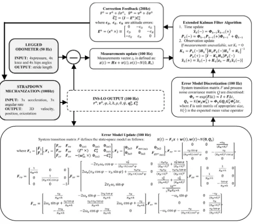
To develop an error model for data fusion, as shown in Fig. 2, we considered the theory regarding sensor error propagation [29]. Our er-ror model is based on the classical 15-state concept described in [30, pp. 35–41] and [31]. We have taken the uncoupled approach to the clas-sical perturbation analysis [30] to obtain equations capturing the error dynamics. These perturbation equations were linearized, and errors of the second order and higher were neglected. Then, the equations were expressed in terms of position, velocity, attitude, and sensor errors to form the desired linearized error model. The appropriate parts of the co-variance matrix of measurement noise were determined by statistically evaluating the precision of the stand-alone LO with respect to reference in velocity and position over more than 100 runs. In order to model the random sensor errors, we employed Allan variance analysis evaluated on sensor noise data. We explored this method in detail in [32]. The original model with appropriate proof can be found in [30].
Due to the nature of the EKF, we constructed the data fusion scheme as a centralized processing approach combined with closed-loop state-vector estimation. The architecture, therefore, corresponds to a complementary filter, where two independent sources of information (position and velocity computed from raw inertial data via strapdown mechanization, and relative position increment obtained from the LO) are combined to compensate for each other’s limitations [33]. In ad-dition, very simple nonholonomic constraints are exploited (modeled as zero mean lateral and vertical body frame velocities with variances determined from analysis of the referential trajectory).
The algorithm of the INS-LO is initialized with calibration param-eters for the inertial sensors; coarse alignment proceeds to estimate the initial heading. While the system is static during initialization, fine alignment algorithm is executed using the same error model in order to estimate the biases of the six inertial sensors used; these biases are then compensated as the navigation proceeds (for details, see previous work [34]). Fig. 2 consists of several blocks.Strapdown Mechaniza-tionblock: The output of the strapdown mechanization is the updated velocity, position, and attitude vectors obtained from the inertial data processed at 100 Hz.LOblock: The LO processes the joint and pres-sure data meapres-sured at 50 Hz. Using a regression function, the stride length is computed for each gait period. The output of the LO over one gait period is converted into position aiding signal that enters the EKF.
Error Model Updateblock: The output of the strapdown mechaniza-tion together with the sensors noise models is used to update the error model at 100 Hz.EKFblock: Since aiding proceeds at 20 Hz, in the meantime, the EKF runs as a predictor with Kalman gain set to zero. If at least one EKF update has occurred, feedback to the strapdown mechanization is provided. Each time this feedback occurs, the errors are corrected and the state vector is reset to zero to prevent unbounded error growth.
III. EXPERIMENTALSETUP
The robot used is 19 cm long and has four identical legs driven by position-controlled servomotors in the hips. In addition, there are four passive compliant joints at the “knees.” A photograph of the robot can be seen in Fig. 1. The mechanical design (weight distribution, proportions, springs used, etc.) is a result of previous research (see, e.g., [35] and [36]). New material (an adhesive skin used for ski touring
Fig. 1. Quadruped robot “Puppy” and its sensory set [19, p. 619].
from Colltex), which has asymmetrical friction properties, was added onto the robot’s feet. This allows the robot to get a good grip during leg retraction (stance), but enables sliding during protraction (swing).
All joints (active hips and passive knees) were equipped with angular position sensors, and every foot had a pressure sensor underneath, sampled at 50 Hz. Xsens IMU was used to measure the inertial data. We applied a simple oscillatory position control of the motors. The target joint angle of each motor γ∗
i (and, hence, of each leg) was
determined as
γ∗
i(t) =Aisin (2πf t+θi) +Bi (1)
where the oscillation can be varied by changing the amplitude Ai,
offsetBi, frequencyf, and phaseθi parameters.
We have investigated two different gaits in [19]. In this work, we wanted to specifically address generalization to different grounds and contributions of individual sensory channels. We have thus used a single gait only: a dynamic right-turning gait derived from a bounding gait, since this gait is stable on a bigger range of terrains (see the multimedia attachment).
During the experiments, the robot was running in an arena of about 2.5× 2.5 m and was tethered. An overhead camera attached to the ceiling was used to record the robot’s movement. Later, the position of a red-colored marker placed roughly above the robot’s COM was tracked together with a green marker above the robot’s head (for head-ing trackhead-ing). Fig. 3 shows a screenshot from the free video trackhead-ing softwareTrackerdepicting the robot in the arena from above. Individ-ual terrains were selected to cover a range of different friction; Table I shows experimentally determined estimates of the static friction coef-ficients between the adhesive skin on the robot’s feet and the different substrates. Since the “skin” has asymmetrical friction properties, coef-ficients in both directions had to be determined.
IV. LEGGEDODOMETERDEVELOPMENT
Stride length is defined as the distance from initial contact of one foot to the following initial contact of the same foot, which essentially corresponds to the distance traveled by the robot in one period of loco-motion. This section is devoted to the development of a new LO, which is superior to the one that we presented in [19]. The development pro-ceeds in the following steps: 1)data collection, 2)feature computation, and 3)training a regression function.
A. Data Collection
Fig. 2. Data fusion scheme for the INS-LO.
mean difference between the real distance and distance measured by the Trackersoftware between two markers placed on the robot. For examples of the trajectories and raw sensory signal plots, see [19].
B. Feature Computation
In line with our previous approach [19], we have used a pool of features that compress the raw sensory signals in each period of loco-motion (these can then be seamlessly related to stride length, which is
Fig. 3. Experimental setup and tracking software: The robot was running in an arena and was tracked from a single camera providing a top view (left). Free tracking software Tracker(http://cabrillo.edu/∼dbrown/tracker/AAPT_ video_modeling_2009.pdf) was used to obtain the referential trajectory.
TABLE I
STATICFRICTIONCOEFFICIENTESTIMATESBETWEENADHESIVESKIN AND DIFFERENTSUBSTRATES
linear combinations, ratios, and multiplications of features of the same modality (e.g.,sum of the means of amplitudes of the left knees and hipswas one feature, orratio between the variances of the front and hind pressure signalsanother). For numerical reasons, all the features were normalized.
C. Training the Regression Function
In our previous work [19], we have first looked for correlations of individual features with stride length, then picked few (four or five) features that performed best, while ensuring that the features are not overlapping (are not based on the same base features). In this study, we have devised a more automatic procedure. We have defined a new linear regression functionh(θ), which processes the features and outputs the estimated stride length. It is defined as follows:
h(θ) = n
i= 0
θixi (2)
wherenis the number of features,xiis a normalized feature value,θi
is corresponding parameter of the regression function, andx0 =1 is the intercept term. The original full feature set (which is composed of single- and cross-channel features) was pruned through experimenta-tion with forward and backward feature selecexperimenta-tion, resulting in around 200 best features in the end.
Training of the regression function is based on a well-known batch gradient descent algorithm which minimizes in least-squares sense the cost functionj(θ) defined as follows:
j(θ) = 1 2m
m
k= 1
(hθ(x{k})−y{k})2 (3)
wheremis the number of training examples,x{k} is the vector of features, andy{k} is the stride length ground truth value for thekth training example.
TABLE II
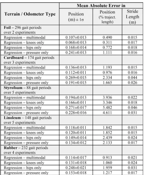
INS-LO OVERALLPERFORMANCE ONDIFFERENTTERRAINS
The update rule for the batch gradient descent is defined as follows (repeated for alliuntil convergence):
θi =θi+α m
k= 1
(y{k}−hθ(x{k}))x{ik} (4)
whereαis the learning rate determined experimentally to assure con-vergence after a reasonable number of iterations.
This procedure can now be universally applied and only the compo-sition of the training set will determine the final form of the regression function. Our goal was to show that the multimodal odometer can gen-eralize to different speeds and previously unseen grounds. Therefore, we have included only three grounds in the training set:plastic foil,
cardboard, and Styrofoam. In addition, one frequency of the motor signal—1 Hz—was also excluded from the training set. With this set-ting, we have created theRegression–StyroFoilCardodometer. Later, when assessing the respective influence of different modalities, the same training procedure is applied, but only features from individ-ual modalities are available. For comparison, we have trained another regression function that uses a single feature—the frequency of loco-motion. This will allow us to contrast the performance of the sensory-based odometer with a simple estimator of the robot’s stride length at different controller settings: different frequencies.
V. EXPERIMENTS ANDRESULTS
TABLE III
INS-LO PERFORMANCEWITHRESPECT TODIFFERENTMODALITIES
experiments was used as testing data to compute the statistics presented in Tables II and III. The results are presented in tabular form, starting with the grounds that were in the training set (but not with the robot running at this frequency of the periodic motor signal), followed by the ones that were completely absent from the training set: linoleum and rubber. Due to the limited size of the arena and different turning radii of the robot on different grounds, duration of the experiments had to be adjusted accordingly. Therefore, the total length of the trajectories varied for each case.
A. Performance Analysis
Table II summarizes the overall performance of the proposed nav-igation system (INS-LO) over all of the five surfaces. The results for the newly developed odometer (Regression–StyroFoilCard) are pre-ceded by the “control” experiments with the frequency-only model, and Universal (ICRA2011) odometer—our previous “heuristic” ap-proach based on correlations and a smaller feature set [19].2 We see that the motion estimation system aided by the new odometer signif-icantly outperforms the other solutions and gives good results even on new grounds. Note that the friction coefficients associated with the new substrates lie outside of the range that was in the training set (see Table I), and stride length has a strongly nonlinear relationship with ground friction in our platform (data not shown here).
When the LO component is switched OFF (only inertial data are pro-cessed), the precision in position degrades rapidly in all experiments: exceeding 0.5-m RMSE in position after 15 s of dynamic motion and 30-m RMSE after 1 min. If the INS component is switched OFF, the
2Note that theUniversal (ICRA2011)odometer was trained on two grounds— Foil and Styrofoam—only.
Fig. 4. Two-dimensional trajectory plot as estimated by the INS-LO, output of the LO used for aiding (stride length projected to the direction of motion using the yaw angle from the IMU), and referential ground truth trajectory (REF).
Fig. 5. (Top) Estimates of thestride length per gait periodas computed by the LO (used for aiding), by the INS-LO, and as obtained from the referential ground truth trajectory (REF). (Bottom) Estimated pitch, roll, and yaw angles corresponding to the motion dynamics.
standalone LO cannot provide 3-D trajectory since no attitude angles are available.
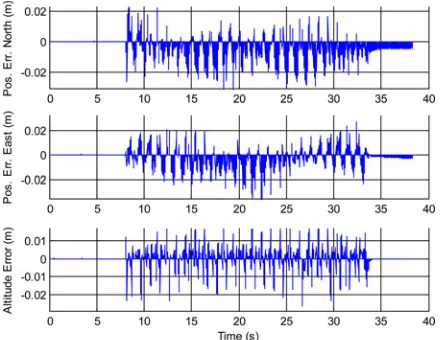
An example of INS-LO performance is presented in the following figures and is based on the new regression odometer, i.e., the mul-timodal odometer trained onStyrofoam, foil, andcardboardterrains. The actual run was performed onlinoleumusing right-turning bound-ing gait of motor frequency 1 Hz. Fig. 4 shows a 2-D projection of the estimated trajectory (INS-LO) compared with the ground truth refer-ence (REF); in this case, the robot was running for approximately 30 s. The estimated stride length values per gait period estimated by the LO are presented in Fig. 5(top) and compared with the stride length com-puted from the reference. The estimated Euler angles are presented in Fig. 5(bottom); the estimated velocity and position vectors are shown in Fig. 6; for the errors in position estimated by the EKF, see Fig. 7.
Fig. 6. Components of the 3-D velocity vector (top) and 3-D position vector (bottom) as estimated by the INS-LO.
Fig. 7. Errors in 3-D position as estimated by the EKF and corrected in the INS-LO feedback.
the INS-LO) averaged over all the gait periods over all the testing ex-periments under the same condition. However, MAE is not a perfect measure, since in dead reckoning the error accumulates with the trav-eled distance. Therefore, in addition, we express the MAE in position as percentage of the total trajectory length. Precision in attitude was not evaluated with respect to ground truth; however, by inspection, the attitude angles were stable. This can be best seen by comparing the attitude at the beginning and end of a trial where the robot had the same posture (in roll and pitch).
B. Modality Analysis
After examining the influence of the different system components— INS, LO and their fusion—in this section, we look more closely at the workings of the LO. By testing three new odometers that rely on features from a single sensory modality (hip joint encoders, knee joint encoders, and pressure sensors), we can assess their respective contributions. They are contrasted with theRegression–StyroFoilCard
odometer, which we will denote here as simply “multimodal.” An overview of the results is presented in Table III.
The results show very good performance of theRegression knees-only which lags only slightly behind the Regression–multimodal
odometer. TheRegression–pressure-only odometer has substantially
worse performance, and theRegression–hips-onlyodometer shows the weakest performance. We offer the following explanation: The hip en-coders largely follow the trajectory of the hip motors and are thus not very sensitive to the interaction with the ground. Pressure sensors on the robot’s feet reflect the force vectors at the robot’s feet and, thus, carry information on the strength of each leg’s push-off and may, indirectly, contain information about slip as well. However, they are sensitive to the exact way a foot hits the ground and to the ground texture (the cardboard and rubber have ridges). The joint encoders at the passive compliant knees are the most effective sensors: They also sense the push-off that each leg can exert when interacting with the ground, but do not suffer from the drawbacks of the pressure sensors. On grounds with higher friction, during leg retraction, the feet slip less and, hence, effectively propel the body forward, while bending the passive knee joint at the same time, which can be detected.
VI. DISCUSSION
In Section I, we discussed the challenges that dynamic locomotion of a quadruped robot poses to analytical modeling. For these reasons, we decided to adopt a data-driven strategy to legged odometry by exploiting multimodal proprioceptive sensory information.
Black-box models often employ complex, nonlinear relationships (see, e.g., [37]). However, we have taken a different approach. We have used a big number of features coming from individual sensory channels and then their simple combinations (sums or ratios). A linear regres-sion function (even though the dynamic relationships are nonlinear) was then sufficient to obtain a good estimate of the stride length. That is, the robot body was used to preprocess and prestructure the sensory signals (see, e.g., [38]). In other words, complex dynamics that present them-selves as a difficulty to motion modeling may at the same time prove to be a benefit for sensing and can be exploited: Sensing occurs through the body dynamics [35]. This is also confirmed by the modality anal-ysis we have performed. For instance, from the single modalities, the potentiometers in the passive compliant knee joints—which are excited by the interaction with the environment—outperform the potentiome-ters in the motor-driven hip joints. A detailed analysis of information flows between motor and sensory channels in our platform is provided in [39].
VII. CONCLUSION
We have developed a navigation algorithm for full body state (po-sition, velocity, and attitude) estimation for a quadruped robot. Our method rests on a unique exploitation of a multimodal proprioceptive sensory set of our legged robot. We have split the sensory modalities into two parts: inertial measurements on one side and joint and pressure information from legs on the other. The EKF was used to provide error estimation and data fusion from two independent sources of informa-tion: thestrapdown mechanization algorithmprocessing raw inertial data andLOproviding relative position aiding, complemented by non-holonomic velocity constraints. The former component was a largely standard white-box model, while for the latter, we have devised a novel data-driven solution (the LO). We argue that this is the best solution in our situation: Although knowledge regarding the physics of inertial measurements is readily available, odometry in our dynamic legged platform is extremely hard to model analytically.
(given by the gait frequency), which is different from the dynamics recorded for the odometer training dataset. Therefore, we have suc-cessfully demonstrated generalization to unknown terrains and speeds. Furthermore, it has to be noted that substantial slippage (accounting for up to 50% difference in speed for the same motor commands on grounds of different friction)—a bottleneck of typical approaches to odometry—is an intrinsic part of the locomotion patterns we studied.
An analysis of the contributions of the individual system components to the overall performance was conducted. In addition, the respective influence of individual sensory modalities that comprise the LO was assessed. If different gaits are used, the odometer’s generalization is limited. This is to be attributed to the very different dynamics of the interaction with the ground and hence different sensory stimulation that arises. However, the same methodology can be applied to train odometers for a different gait, as we have shown previously [19]. For a different quadruped platform, the particular odometer (regression func-tion) proposed here would not work. However, what we propose as a general approach is to equip any robot with a rich multimodal sensor set. Then, using a data-driven approach, it is very likely that informa-tion about many variables of interest can be delivered. For example, in [40], we have shown how the same sensory set can be employed for successful terrain classification in our platform. This contrasts with traditional approaches that add sensors specifically targeted at measur-ing desired quantities.
ACKNOWLEDGMENT
The authors would like to thank F. Iida for the development of the robot, H. Marques for the IMU, D. Brown for theTracker free software, R. Pfeifer for continuous support, F. Iida and D. Scaramuzza for reviewing an earlier version of the manuscript, and the anonymous reviewers for their constructive suggestions that greatly improved the manuscript.
REFERENCES
[1] S. Se, D. Lowe, and J. Little, “Vision-based global localization and map-ping for mobile robots,”IEEE Trans. Robot., vol. 21, no. 3, pp. 364–375, Jun. 2005.
[2] L. Moreno, J. Armingol, S. Garrido, A. Escalera, and M. Salichs, “A genetic algorithm for mobile robot localization using ultrasonic sensors,” J. Intell. Robot. Syst., vol. 34, no. 2, pp. 135–154, 2002.
[3] P. Goel, S. I. Roumeliotis, and G. S. Sukhatme, “Robust localization using relative and absolute position estimate,” inProc. IEEE/RSJ Int. Conf. Intell. Robots and Syst., 1999, pp. 1134–1140.
[4] A. Etienne and K. Jeffery, “Path integration in mammals,”Hippocampus, vol. 14, pp. 180–92, 2004.
[5] F. H. Durgin, M. Akagi, C. R. Gallistel, and W. Haiken, “The preci-sion of locometry in humans,”Exp. Brain Res., vol. 193, pp. 429–436, 2009.
[6] M. Wittlinger, R. Wehner, and H. Wolf, “The ant odometer: stepping on stilts and stumps,”Science, vol. 312, pp. 1965–1967, 2006.
[7] G. Dissanayake, S. Sukkarieh, E. Nebot, and H. Durrant-Whyte, “The aiding of a low-cost strapdown inertial measurement unit using vehicle model constraints for land vehicle applications,”IEEE Trans. Robot. Au-tom., vol. 17, no. 5, pp. 731–747, Oct. 2001.
[8] J. Yi, H. Wang, J. Zhang, D. Song, S. Jayasuriya, and J. Liu, “Kinematic modeling and analysis of skid-steered mobile robots with applications to low-cost inertial measurement-unit-based motion estimation,”IEEE Trans. Robot., vol. 25, no. 5, pp. 1087–1097, Oct. 2009.
[9] H. Rehbinder and H. Xiaoming, “Drift-free attitude estimation for accel-erated rigid bodies,”Automatica, vol. 40, pp. 653–659, 2004.
[10] J. A. Cobano, J. Estremera, and P. Gonzalez de Santos, “Location of legged robots in outdoor environments,”Robot. Auton. Syst., vol. 56, pp. 751–761, 2008.
[11] G. P. Roston and E. P. Krotkov, “Dead reckoning navigation for walking robots,” inProc. IEEE/RSJ Int. Conf Intell. Robots Syst., 1992, pp. 607– 612.
[12] O. Gur and U. Saranli, “Model-based proprioceptive state estimation for spring-mass running,” presented at the Robot.: Sci. Syst. VII Conf., Los Angeles, CA, 2011.
[13] S.-H. Liu, T.-S. Huang, and J.-Y. Yen, “Comparison of sensor fusion methods for an SMA-based hexapod biomimetic robot,”Robot. Auton. Syst., vol. 58, no. 5, pp. 737–744, 2010.
[14] A. Chilian, H. Hirschmuller, and M. Gorner, “Multisensor data fusion for robust pose estimation of a sixlegged walking robot,” inProc. IEEE/RSJ Int. Conf. Intell. Robots Syst., 2011, pp. 2497–2504.
[15] P.-C. Lin, H. Komsuoglu, and D. E. Koditschek, “A leg configuration measurement system for full body posture estimates in a hexapod robot,” IEEE Trans. Robot., vol. 21, no. 3, pp. 411–422, Jun. 2005.
[16] P.-C. Lin, H. Komsuoglu, and D. E. Koditschek, “Sensor data fusion for body state estimation in a hexapod robot with dynamical gaits,”IEEE Trans. Robot., vol. 22, no. 5, pp. 932–943, Oct. 2006.
[17] M. Bloesch, M. Hutter, M. Hoepflinger, S. Leutenegger, C. Gehring, D. Remy, and R. Siegwart, “State estimation for legged robots— Consistent fusion of leg kinematics and IMU,” inProc. Robot.: Sci. Syst. VIII, 2012.
[18] M. Maimone, Y. Cheng, and L. Matthies, “Two years of visual odometry on the mars exploration rovers: Field reports,”J. Field Robot., vol. 24, no. 3, pp. 169–186, 2007.
[19] M. Reinstein and M. Hoffmann, “Dead reckoning in a dynamic quadruped robot: Inertial navigation system aided by a legged odometer,” inProc. IEEE Int. Conf. Robot. Autom., 2011, pp. 617–624.
[20] D. H. Titterton and J. L. Weston,Strapdown Inertial Navigation Technol-ogy. Lavenham, U.K.: Lavenham, 1997.
[21] P. G. Savage, “Strapdown inertial navigation integration algorithm design—Part 1: Attitude algorithms,” J. Guid., Control Dyn., vol. 21, no. 1, pp. 19–28, 1998.
[22] P. G. Savage, “Strapdown inertial navigation integration algorithm design part 2: Velocity and position algorithms,,”J. Guid., Control, Dyn., vol. 21, no. 2, pp. 208–221, 1998.
[23] O. Salychev, Applied Inertial Navigation: Problems and Solutions. Moscow, Russia: Bauman MSTU, 2004.
[24] E.-H. Shin, “Estimation techniques for low-cost inertial navigation,” Ph.D. dissertation, Dept. Geomatics Eng., Univ. Calgary, Calgary, AB, Canada, 2005.
[25] M. Sipos, P. Paces, M. Reinstein, and J. Rohac, “Flight attitude track reconstruction using two AHRS units under laboratory conditions,” in Proc. IEEE Sens., 2009, pp. 675–678.
[26] M. Reinstein, J. Rohac, and M. Sipos, “Algorithms for heading deter-mination using inertial sensors,”Przeglad Elektrotech., vol. 86, no. 9, pp. 243–246, 2010.
[27] R. E. Kalman, “A new approach to linear filtering and prediction prob-lems,”ASME J. Basic Eng., vol. 82, pp. 34–45, 1960.
[28] W. Abdel-Hamid, “Accuracy enhancement of integrated MEMS-IMU/GPS systems for land vehicular navigation applications,” Ph.D. dis-sertation, Dept. Geomatics Eng., Univ., Calgary, AB, Canada, 2005. [29] M. S. Grewal and A. P. Andrews,Kalman Filtering – Theory and Practice
using Matlab. New York: Wiley-Interscience, 2001.
[30] E.-H. Shin, “Accuracy improvement of low cost INS/GPS for land appli-cations,” M.S. thesis, Dept. Geomatics Eng., Univ. Calgary, Calgary, AB, Canada, 2001.
[31] N. V. Kumar, “Integration of inertial navigation system and global posi-tioning system using Kalman filtering,” M.S. thesis, Dept. Aerosp. Eng., Indian Inst. Technol. Bombay, Mumbai, India, 2004.
[32] M. Reinstein, M. Sipos, and J. Rohac, “Error analyses of attitude and heading reference systems,”Przeglad Elektrotech., vol. 85, no. 8, pp. 115– 118, 2009.
[33] S. B. Lazarus, I. Ashokaraj, A. Tsourdos, R. Zbikowski, P. Silson, N. Aouf, and B. A. White, “Vehicle localization using sensors data fusion via inte-gration of covariance intersection and interval analysis,”IEEE Sensors J., vol. 7, no. 9, pp. 1302–1314, Sep. 2007.
[34] M. Reinstein, “Evaluation of fine alignment algorithm for inertial naviga-tion,”Przeglad Elektrotech., vol. 87, no. 7, pp. 255–258, 2011. [35] F. Iida and R. Pfeifer, “Sensing through body dynamics,”Robot. Auton.
Syst., vol. 54, no. 8, pp. 631–640, 2006.
[37] U. Forssell and P. Lindskog, “Combining semi-physical and neural net-work modeling: An example of its usefulness,” inProc. 11th IFAC Symp. Syst. Identification, 1997, pp. 767–770.
[38] M. Lungarella and O. Sporns, “Mapping information flow in sensorimotor networks,”PLoS Comput. Biol., vol. 2, no. 10, pp. 1301–1312, 2006. [39] N. Schmidt, M. Hoffmann, K. Nakajima, and R. Pfeifer, “Bootstrapping
perception using information theory: Case studies in a quadruped robot running on different grounds,”Adv. Complex Syst. J., vol. 16, 2012. [40] M. Hoffmann, N. Schmidt, R. Pfeifer, A. Engel, and A. Maye, “Using
sensorimotor contingencies for terrain discrimination and adaptive walk-ing behavior in the quadruped robot Puppy,” inFrom Animals to Animats 12: Proc. Int. Conf. Simulation Adaptive Behaviour, 2012, pp. 54–64.
Parallelizing RRT
on Large-Scale Distributed-Memory Architectures
Didier Devaurs, Thierry Sim´eon, and Juan Cort´es
Abstract—This paper addresses the problem of parallelizing the Rapidly-exploring Random Tree (RRT) algorithm on large-scale distributed-memory architectures, using the message passing interface. We compare three parallel versions of RRT based on classical parallelization schemes. We evaluate them on different motion-planning problems and analyze the various factors influencing their performance.
Index Terms—Distributed memory, message passing, parallel
algo-rithms, path planning, rapidly-exploring random tree (RRT).
I. INTRODUCTION
Due to a wide range of applications, sampling-based path planning has benefited from considerable research effort. It has proven to be an effective framework for various problems in domains as diverse as autonomous robotics, aerospace, manufacturing, virtual prototyping, computer animation, structural biology, and medicine. These appli-cation fields yield increasingly difficult, highly-dimensional problems with complex geometric and differential constraints.
The Rapidly-exploring Random Tree (RRT) is a popular sampling-based algorithm applied to single-query path-planning problems [2]. It is suited to solve robot motion-planning problems that involve holo-nomic, nonholoholo-nomic, kinodynamic, or kinematic loop-closure con-straints [2]–[4]. It is also applied to planning in discrete spaces or for hybrid systems [5]. In computational biology, it is used to analyze genetic network dynamics [6] or protein–ligand interactions [7]. How-ever, when applied to complex problems, the growth of an RRT can
Manuscript received April 6, 2012; revised October 29, 2012; accepted December 21, 2012. Date of publication January 29, 2013; date of current ver-sion April 1, 2013. This paper was recommended for publication by Associate Editor D. Hsu and Editor D. Fox upon evaluation of the reviewers’ comments. This work was supported in part by the HPC-EUROPA project (RII3-CT-2003-506079, with the support of the European Community—Research Infrastructure Action under the FP6 “Structuring the European Research Area” Program) and in part by the French National Agency for Research under project GlucoDesign and by the European Community under Contract ICT 287617 “ARCAS.”
The authors are with CNRS, LAAS, 7 avenue du colonel Roche, F-31400 Toulouse, France, and also with Univ de Toulouse, LAAS, F-31400 Toulouse, France (e-mail: [email protected]; [email protected]; [email protected]).
Color versions of one or more of the figures in this paper are available online at http://ieeexplore.ieee.org.
Digital Object Identifier 10.1109/TRO.2013.2239571
become computationally expensive [8]–[11]. Some techniques have been proposed to improve the efficiency of RRT by controlling the sampling domain [8], reducing the complexity of the nearest neighbor search [9], or using gap reduction techniques [10].
Our objective is to further investigate improvements to RRT by ex-ploiting speedup from parallel computation. Some results have been obtained in that direction (see Section II). Nevertheless, the existing study considers mainly shared-memory architectures and small-scale parallelism, up to 16 processors [12]–[14]. In this study, we are inter-ested in what can be achieved by larger scale parallelism. We focus on parallelizing RRT on distributed-memory architectures, which requires the use of the message passing interface (MPI).
In this paper, we compare three parallel versions of RRT based on classical parallelization schemes: ORparallel RRT, distributed RRT, and manager–worker RRT. Besides the algorithms themselves, we also present the main technicalities involved in their development (see Section III). Our contribution focuses on evaluating these algorithms on several motion-planning problems and showing their differences in behavior (see Section IV). We also analyze their performance in or-der to unor-derstand the impact of several characteristics of the studied problems (see Section V). Our evaluation shows that parallelizing RRT with MPI can provide substantial performance improvement in two cases: 1) problems for which the variability in sequential runtime is high can benefit from theORparallel RRT and 2) problems for which the computational cost of an RRT expansion is high can benefit from the distributed RRT and the manager–worker RRT. Even though this is not true for most academic motion-planning benchmarks, many robotic examples yield computationally expensive RRT expansions and can, thus, benefit from these parallel algorithms (see Section IV-F).
II. RELATEDWORK
A. Parallel Motion-Planning
The idea of improving motion-planning performance using parallel computation is not new. A survey of some early work proposes a classification scheme to review various motion-planning approaches and related parallel processing methods [15]. A more recent trend is to exploit the multicore technology available on many of today’s PCs, which allows having multiple threads collaboratively solving a problem [16]. Another recent trend consists of using shared-memory models on many-core graphics processing units (GPUs) [17].
Among classical approaches, theembarrassingly parallel paradigm
exploits the fact that some randomized algorithms, such as the prob-abilistic road map (PRM), are what is termed “embarrassingly paral-lel” [18]. The massive inherent parallelism of the basic PRM algorithm enables to reach a significant speedup, even with simple parallelization strategies, especially on shared-memory architectures. In this approach, computation time is minimized by having several processes coopera-tively building the road map.
Another simple approach is known as theorparallel paradigm. It was first applied to theorem proving, before providing a parallel for-mulation for the randomized path planner (RPP) [19]. Its principle is to have several processes running the same sequential randomized algo-rithm, where each one tries to build its own solution. The first process to reach a solution reports it and broadcasts a termination message. The idea is to minimize computing time by finding a small-sized solution. Despite its simplicity, this paradigm has been successfully applied to other randomized algorithms [20].
A more sophisticated approach is thescheduler–processor scheme
that was developed to distribute the computation of the sampling-based roadmap of trees (SRT) algorithm [21]. In this scheme, the scheduler coordinates the processors constructing the milestones, which can be
![Fig. 1.Quadruped robot “Puppy” and its sensory set [19, p. 619].](https://thumb-ap.123doks.com/thumbv2/123dok/3124200.1728066/3.594.303.548.67.159/fig-quadruped-robot-puppy-sensory-set-p.webp)