1/36
METALS
[
Adopsi dari:
Zbigniew D Jastrzebski, “The Nature And Properties of Engineering2/36
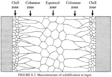
FIGURE 8-2 Macrostructure of solidification in ingot.
Segregation. During solidification of the alloy, variations in concentration occur in certain regions of the melt, resulting in segregation. Two main types of segregation can be distinguished: macrosegregation and microsegregation. In macrosegregation, composition changes in the melt occur over large distances. This may be caused by gravity segregation, normal segregation, and inverse segregation. Gravity segregation is caused by differences in densities of the components of the melt. In normal segregation, the solute is rejected at an advancing solid—liquid interface because of different diffusion rates in solid and in liquid. Inverse segregation is caused by outward move ment of the impurity-enriched interdendritic liquid, thereby increasing the average impurity Content at the head of the ingot.
Microsegregation refers to composition variation over very small distances, usually one or several millimeters. Foreign particles insoluble in both solid and liquid, such as particles of slag and furnace refractories remaining from extractive metallurgical processes, may be trapped during solidification, resulting in segregation at the grain boundaries. As the result of the composition changes in the liquid during freezing, constitutional supercooling may develop during crystal growth. This can occur both in stirred and in unstirred melts, causing microsegregation effects that run in the growth direction on a scale of about 100 µm. To reduce or eliminate constitutional supercooling and the associated microsegregation effects proper control of temperature gradient, cooling rates, and degree of mixing must be observed.
3/36
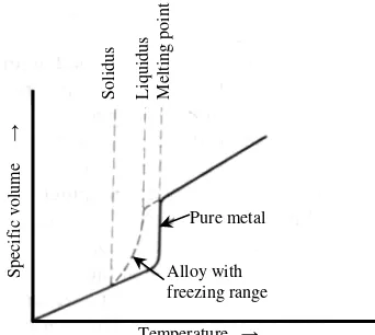
Shrinkage. Most commercially important metals and alloys undergo substantial contraction in volume when cooled from the liquid to the solid state. The resultant shrinkage is equal to the difference in volume between the liquid at the pouring temperature and the solid metal at room temperature. The total change in volume is the combined effect of the contraction of the liquid when cooled from its casting temperature to its freezing point, the contraction during freezing from liquid to solid, and the contraction of the solid metal when cooled from its freezing point to room temperature (Fig. 8-3).
Shrinkage may cause the formation of cavities in a casting, adversely affecting the properties of the metal. Such cavities, particularly in the form of piping, may cause considerable damage to the metal since, if air penetrates into the cavity, it will oxidize the metal (Fig. 8-4).
The presence of oxide layers inside the ingot will prevent the welding out of cavities during subsequent rolling or forging operations of the ingot. To minimize piping, molds with tapered walls of the big end-up type are used in conjunction with a hot-top or insulated riser as shown in Fig. 8-1. Solidification of the metal at the top is
delayed, permitting the liquid metal to penetrate into any cavities and pores that may have already formed in frozen parts of the ingot.
Gas Porosity. Many metals dissolve considerable amounts of gases in their liquid state. The solubility of these gases is much less in the solid than in the liquid metal and decreases as temperature decreases, the exact opposite of the solubility of gases in aqueous solutions. Consequently, the gases will escape from the melt during solidification, forming blowholes and pinholes in the metal. This results in undesirable porosity that may considerably impair the properties of the solid metal or alloy. Pinholes are very small blowholes formed mostly on the surface of the casting; inside the casting blowholes are much larger. Blowholes are not as serious in ingots as in castings because, for the most part, they will be eliminated from the ingot on subsequent rolling and forging. Since the presence of blowholes is concealed from direct observation, castings are less reliable in important applications than wrought metals unless thoroughly examined for porosity.
The number of blowholes in the solid metal depends on the melting and casting technique as well as on the affinity of the molten metal for the dissolved gases.
To remove or reduce the gases from the molten metal, vacuum degassing Is used in steel-making operations. This can be accomplished by stream degassing, during which the molten steel streams through the nozzle into a large vacuum chamber, where it loses gas. The amount of dissolved gas can also be greatly reduced by chemical action such as the removal of oxygen as carbon monoxide by carbon deoxidation or by using deoxidizers such as aluminum, manganese, or silicon, which react with the oxygen in steel forming
FIGURE 8-3 Contraction on solidifying and cooling metals and alloys.
Sp ec if ic v ol um e → So lid us L iq ui du s M el tin g po in t Pure metal Alloy with freezing range
Temperature →
FIGURE 8-4 Ingot metal showing piping. Big end down without hot top.
Pipe
4/36
oxides. This latter method has the disadvantage of leaving in the metal small particles of oxidized products such as alumina or silica.
Impurities and Inclusions. Impurities in the form of oxides, sulfides, and silicates may be present in metals either in solid solution or as separate particles called inclusions. Such impurities generally impair the properties of the metal or alloy but, in some cases, they may actually prove advantageous. The presence of sulfur in steel, lead in brass or steel, and tellurium in copper has beneficial effects on the machining properties of these metals.
8-2 RAPID SOLIDIFICATION PROCESSES
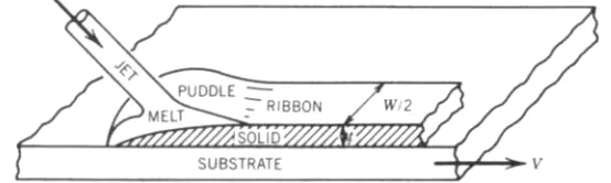
Rapid solidification processes (RSP) involve high cooling rates ranging from 102 to 1010 K s−1 (degrees Kelvin per second). Such processes have been used to produce very fine-grained structural metals, metallic glasses, and very fine reactive powders for a wide range of applications. Such high cooling rates can only be achieved by spreading a thin layer of liquid in a perfect contact with a highly conductive substrate such as metal or sapphire (Fig. 8-5). The rate of quenching is determined by the liquid—substrate heat transfer and the thermal conductivity of the liquid layer. For cooling rates of 102, 106, and 1010 K s−1 the dimensions of a section cannot exceed 10mm, 0.1 mm, and 10 µm, respectively. In conventional solidification processes, cooling rates are about 10−1 to 10−2 K s−1. The lowest cooling rates of about 10−5 to 10−6 K s−1 are present in very large sand castings.
Amorphous or glassy solids can also be produced by methods in which the liquid state is bypassed completely. These may involve the deposition of solid from the vapor phase by thermal evaporation, decomposition of gaseous compounds by radiofrequency discharges, sputtering, or deposition from salt solution by electrolysis. These techniques provide a very high and effective quenching rate and give amorphous solids and metallic glasses that cannot be formed by liquid quenching. The consequence of high cooling rates is a supercooling of the melt by hundreds of degrees before any solid phase can form. This may cause a number of unusual structural and morphological effects such as refinement of dendrites and grain size, extension of solid solubility limits, reduction of segregation, formation of metastable crystalline phases and finally complete noncrystallization (metallic glasses).
FIGURE 8-5 The flow patterns of impinging melt during solidification. (Annual Review of Materials Science, Vol 10, p. 380, Fig. 6b)
5/36
Metallic Glasses. Metallic glasses are produced at relatively high cooling rates, 105 K s−1 and higher, which can be attained by one of the RSR processes such as split quenching,
≈109 K s−1 melt; casting, 106 K s−1; and water quenching, ≈ 103 K s−1 (Fig. 8-5). Metallic
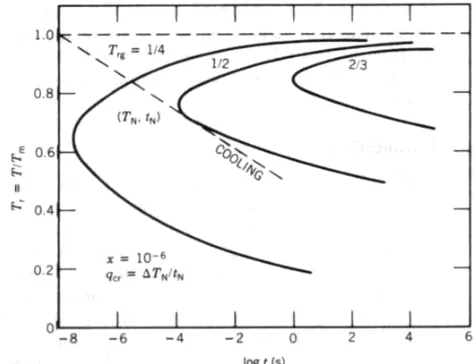
glasses of commercial interest are metal—metalloid alloys combining various amounts of iron, nickel, and cobalt with about 15% to 30% of such elements as boron, silicon, carbon, and phosphorus. The glass-forming ability (GFA) of metals and alloys is enhanced in the eutectic region of the phase equilibrium diagram at which the liquidus temperature T1 reaches a minimum and the interval between the liquid temperature T, and the glass transition temperature Tg is the shortest. The ratio Tg/T1, called the reduced transition temperature Trg, can be used as a measure of the glass-forming ability of an alloy. The higher the Trg the easier it is to form metallic glass. The ability to form the metallic glass is also dependent on quenching conditions and on the alloy composition. (See Fig. 8-6.)
For pure metals Trg is only 0.25 requiring cooling rates of about 1012 s−1, making it difficult to achieve glass by the present available quenching technique. However, for transition binary metal alloys Trg is about 0.5, making it easier to produce glasses. A still lower Trg, about 0.66, is shown for a ternary alloy. Generally the stability of metallic glasses increases upon alloying as has been found in such systems as Fe80P17C3, (Fe, Co, Ni, Mo, Cr)75P16B6Al3 Fe80B17Si3, and (Zr, Ti)60Be59.
Metallic glasses are very hard and strong. Crystalline alloys seldom attain a strength greater than 1% of their theoretical strength because of the presence of dislocations, grain boundaries, and other defects which lowers the strength. The disordered atomic structure of metallic glasses prevents the existence of such defects resulting in strong and hard materials. The chemical homogeneity of the single phase nature of metallic glasses as compared to their crystalline products gives them a much higher corrosion resistance. For example, the glassy alloys containing chromium and phosphorus show much better corrosion resistance than crystalline 18Cr—8Ni stainless steel. Similarly rapidly quenched aluminum alloys, to which Cr, Mn, and Mg have been added, exhibit superior corrosion resistance to seawater, exceeding greatly the conventional resistance of aluminum (Mn and Mg) alloys. Metallic glasses can find a number of important technological applications such as high-strength fibers in composites, catalysts, protective coatings and others. Because of their high electrical resistivity and the absence of grain boundaries, iron-based metallic glasses are excellent magnetic materials for transformer cores, various electronic devices, magnetic tape heads of high permeability and saturation magnetism, with high wear resistance and small magnetostriction.
FIGURE 8-6 Time—temperature transformation (TTT) curves of metals
with various reduced glass temperatures Trg = Tg/Tm. (Annual Review of
6/36
FORMING PROCESSES
The ingots or billets produced during solidification are fabricated by plastic deformation in order to obtain the desired shape and configuration of the final products. Castings are used without further deformation, and they retain the shape and properties resulting from the casting procedure.
Although practically any metal or alloy can be cast, there are limited materials of adequate castability. The greatest difficulty in production of a serviceable casting arises from shrinkage of metals during cooling from the liquid to the solid state at room temperature. The best casting alloys are those that have low shrinkage and short freezing ranges, so that they solidify by forming a solid shell at the mold walls, the thickness of which increases steadily with time. For sound castings favorable temperature gradients must be established in the freezing metal. Freezing must start at the farthest point within the feeding range of a particular riser and continue directionally toward the riser without the freezing of any intervening section before feeding is complete. This requires a proper design for the mold and adequate control of the fluidity of the molten metal, as well as uniform temperature gradients. To meet these requirements, various casting methods are being used according to the type of metal or alloy to be cast and the properties desired in the casting. The methods used are sand casting, die casting, permanent mold casting, centrifugal casting, investment casting, and continuous casting.
The continuous casting process has been used recently for steel up to 6.5x103 mm2 in section. The liquid steel is poured into a vertical water-cooled mold from which it is gradually withdrawn as a solid below the die. A variable-speed roll draws the metal at a rate adjustable up to about 1 m/s. The casting speed is controlled so that a desirable grain structure, usually columnar, is produced. The rate of crystal growth depends on the casting speed and on the angle between casting and the growth direction. The Continuous casting
processes are also being developed for other metals and alloys as. for example, horizontal casting of copper alloys.
8-3 MECHANICAL WORKING
The products manufactured by plastic or mechanical deformation are referred to as wrought metals and alloys. Subjecting metals to mechanical working during shaping operations improves the properties of the wrought products over that of the cast product. Plastic deformation, when carried out below the recrystallization temperature, results in work hardening, which improves the mechanical properties of metals and also contributes to the development of a microstructure tougher or more desirable than that formed during casting operations. This mechanical working of metals can be accomplished by various processes such as forging, rolling, extrusion, stamping, drawing, and pressing.
In all these processes the flow of metal is caused by application of the external force or pressure necessary to push or pull a piece of metal through a die. The pressure required to produce such plastic flow is determined largely by the yield stress of the material which, in turn, controls the load capacity of the machinery required to accomplish desirable changes in shape. The pressure used to overcome the inherent material resistance during homogeneous plastic deformation can then be given as
ε σy
P==== (8.1)
where ε= the strain resulting during the deformation
y
σ = the yield stress of the material
It is convenient to use the value of the natural strain
2 1
ln
A A
====
7/36
where A1 and A2 are the initial and final cross sections of the workpiece, respectively. Thus
2 1
ln
A A
P====σy (8-3)
The pressure so calculated is generally much lower than that required under actual working operations. This is because in addition to the resistance during homogeneous plastic flow, there are losses caused by friction between the workpiece and the die and internal losses caused by inhomogeneous plastic deformation and other factors, such as work hardening. For example, the value of P as calculated by Equation 8-3 is only 30% to 55% of the actual working pressure required for extrusion, 50% to 70% of the pressure required for wire drawing, and 80% to 90% of the pressure required for strip rolling. The total work W required for the actual forming operation can be estimated as the sum of three terms:
W = Wp + Wf + W1 (8.4) where Wp = the work used to accomplish homogeneous plastic deformation
Wf = the work used to overcome frictional resistance W1 = the work used for internal losses within a metal
Forging. Forging is a major method of shaping very large castings by forces that may be either steadily increased in a press or applied by hammering. Since mainly compressive forces are in operation during forging, tensile necking and fracture are avoided. Several forging methods are available, but all of them may be grouped into two main categories: pressing and hammering. Pressing is the relatively slow deformation of metal to the required shape between mating dies. Pressing is preferred for homogenizing large ingots because the deformation zone extends throughout the cross section. In hammering the more rapid deformation is restricted mainly to the surface region. Drop-forging, hammering, and swaging can be performed with lighter equipment, although a drop-hammer itself may weigh several tons. In swaging a small cylindrical rod is forged by passage through a rotary machine in which it is hammered by converging dies. This is particularly useful for shaping more brittle metals without fracture. Large forgings require very large forces and they are usually worked at elevated temperatures (hot working), even though the equipment required is very heavy. Forging is usually applied to produce objects of irregular shape.
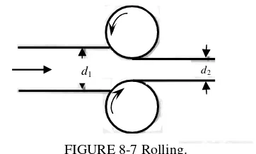
Rolling. Rolling is widely used for both hot working and cold working of many metals and alloys. In rolling, the metal is continuously passed between rotating rollers (Fig. 8-7). The rolling process is much more economical than forging, since it is quicker, consumes less power, and produces long items of uniform cross section.
Deformations are restricted to a small
volume at any given time, so the loads can be relatively low. The ingot is drawn continuously through the rolls by the friction force between the surfaces of the rolls and the metal. The metal is subjected to a longitudinal tension force that combined with the normal force produces the shear stress τ, which causes deformation.
p f ××××
====
τ (8-5) where p = the normal stress
f = the coefficient of friction
FIGURE 8-7 Rolling.
8/36
In cold rolling of wide strips it is possible to attain speeds up to 25 m/s for thin strips. When thin hard strips are rolled, it is not possible to reduce the thickness below a certain limit because greater deformation of the rolls than of the strips can occur. To obtain the thinnest strip possible, the metal should be annealed, the coefficient of friction should be as low as possible, and small-diameter rolls should be used.
Extrusion. Extrusion involves pressing a billet or slug of metal by movement of a ram through an orifice or nozzle (Fig. 8-8a). During extrusion, both compressive and shear forces are developed; however, there are no tensile forces present. It is therefore possible to deform the metal very heavily without fracture. Under the influence of the applied force, the metal is continuously deformed as it is pushed through a die and is shaped into a long bar of desired cross section. In the case of tubes, the extrusion is carried out through a round die. and a mandrel, integral with the ram, is pushed through the previously pierced billet. Two main extrusion processes are direct extrusion and inverted extrusion. In direct extrusion, the pressure ram is advanced toward the die assembly; in indirect extrusion, the die is moved down the container bore. This latter movement is characterized by a simpler flow and lower extrusion pressures; however, the operation must employ a hollow ram along which the extruded product can pass after being formed in the die (Fig. 8-8b). Consequently, in indirect extrusion, frictional losses are much smaller, since there is no relative movement of billet and container and the deformation is confined only to a zone near the die. The efficiency of the extrusion is measured by the ratio of the work necessary for deformation to the total work expended. This latter is the sum of the work necessary for deformation, for overcoming frictional resistance at the billet—container and the billet—die interfaces, and the work expended in straining not required for shape change. Initially, extrusion was mainly used for lower-melting, nonferrous metals but, with improvements in lubricants and development of powerful presses, the extrusion of higher-melting metals such as steel becomes more and more important. Most carbon and stainless steels can now be extruded at temperatures of about 1200°C (2190°F) using glass as a lubricant. Glass is cheap, is relatively easy to use, is stable under most extrusion conditions, does not react with iron, and helps to dissolve any oxide layer on the metal surface. Although extrusion was first limited to hot working operations, recent development of powerful presses and high-pressure lubricants makes cold extrusion more and more important in metal-working operations. Modern extrusion processes can now be run automatically, making complex sections, particularly in metals such as brass and aluminum. The mechanical properties of cold extruded products are very good.
FIGURE 8-8 (a) Direct extrusion of tubes. (b) Inverse extrusion
Container
Container Billet Tube
(a)
(b) Container
Billet Billet
9/36
Other Forming Processes. Wire drawing, deep drawing, and swaging are forming processes used for a variety of applications. Wire drawing involves pulling the stock through a tungsten carbide die having a tapered bore. Large quantities of rods, tubes, and wires are produced by this technique. Usually the reduction of the rod area is limited to about 30% so that, for a fine wire, the process consists of a long series of successive wire drawing operations through subsequent dies of suitable diameters. Deep drawing is a forming process used to shape metals into bowls, cups, panels, and similar shapes. In deep drawing the metal is deformed by flowing rapidly inward and then turning the corner to become the wall of the cup. The amount of drawing in a single operation should be such that the ratio of height to diameter of the article formed does not exceed one. If this ratio exceeds one the article must be made by redrawing in one or more steps. Recently, high-pressure and very high speed processes of formation have been introduced. Under very high pressure the ductility of metal considerably increases, permitting the combination of otherwise separate operations. Explosive forming involves the application of very high pressures ranging from 700 MPa (101.5 ksi) to over 7 GPa (1015 ksi) over a very short period of time (microseconds). In most industrial processes this is accomplished by producing an intense pressure pulse in a liquid medium caused by detonation of an explosive or explosion of a wire by a sudden passage of very high currents. The shock wave generated in liquid forces a metal blank against a shaping die, causing the required deformation. The pressure wave produces uniaxial compression involving shear and volume changes. The strain rates are about 105 s−1 and sometimes as high as 108 s−1.
8-4 SUPERPLASTICITY
Certain alloys when deformed in tension at elevated temperatures exhibit extensive plastic deformation showing a strain which may exceed 1000% and more without necking. This phenomenon, called superplasticity, presents a new way of fabricating certain metals and alloys by methods so far used only for glass and plastics. However, the extensive use of superplasticity in forming processes has been restricted by the fact that the strain rates in the region of superplastic deformation are much lower than that used in conventional hot working processes. Considerable efforts are made to determine all the conditions leading to extended superplasticity over higher ranges of strain rates. Superplasticity is a high-temperature phenomenon occurring at about half of the absolute melting point (0.5 Tm) of the material that has characteristic microstructure consisting of a uniform ultrafine equiaxed grains smaller than 10 µm and stable during the superplastic deformation.
The flow stress causing superplastic strain is highly sensitive to the strain rate, ε&, and
can be described by equation
m
Kε
σ==== & (8-6)
where σ= the flow stress ε& = the strain rate
K = the material constant that depends on temperature and microstructure m = the strain sensitivity factor
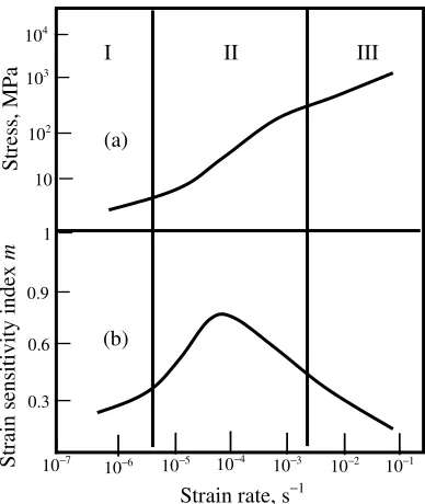
On plotting log stress versus log strain rate (Fig. 8-9a) a characteristic sigmoidal curve is obtained. The slope of the curve at any particular strain rate is given by
ε δ
σ δ
&
log log ====
10/36
FIGURE 8-9 Superplastic behavior of an alloy. (a) A plot of log stress versus log strain rate, ε& . (b) Changes in the strain sensitivity index m with strain rate
ε
& . (After D. Lee, Acta Metallurgica, 17, 1057. 1969.)
The value of m changes with the strain rate (see Fig. 8-9b) and in regions I and III, m < 0.3. In superplastic region II, where large elongation without necking occurs, m > 0.3, reaches its maximum of about 0.6 up to 1.0, and then drops to its initial values less than 0.3 for regions I and III. The strain rate sensitivity factor m is a measure of the necking
resistance of the material during superplastic deformation.
(a)
(b)
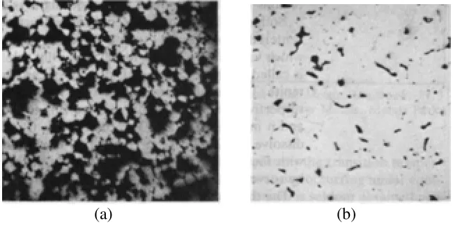
FIGURE 8-10 Microstructures of zinc—aluminum alloy (78% Zn—22% Al) at 800 X. (a) Alloy in a superplastic state showing very fine duplex microstructure produced from a single-phase alloy on quenching from above 275°C in cold water. (b) Alloy
in conventional metal state (not superplastic) showing coarse microstructure resulting on slow cooling from above 275°C. (The Western Electric Engineer. Vol.
XV. No. 1. January 1971).
The maximum ductility depends on the imposed strain rate, the temperature, and the initial grain size. The highest ductility as measured by elongation is usually found at an intermediate strain rate, and it decreases in both higher and lower strain rate regions. Increasing the deformation temperature reduces the flow stress and causes higher strain rates between regions I and Il and between regions II and Ill. A proper heat treatment of a superplastically formed component changes its microstructure from very fine equiaxed grains to coarser ones and the alloy ceases to be superplastic (Fig. 8-10).
Strain rate, s−1
St
ra
in
s
en
si
tiv
ity
in
de
x
m
St
re
ss
, M
Pa
II I
(a)
(b)
III
|
10−1
104
−
103
−
102
−
10
−
1
−
0.9
−
0.6
−
0.3
−
|
10−7 |
10−6
|
10−5 10| −2
|
11/36
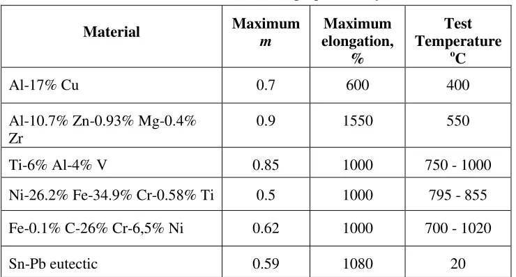
Table 8.1. Some selected superplatic alloys
Material Maximum m
Maximum elongation,
%
Test Temperature
o
C
Al-17% Cu 0.7 600 400
Al-10.7% Zn-0.93% Mg-0.4%
Zr 0.9 1550 550
Ti-6% Al-4% V 0.85 1000 750 - 1000
Ni-26.2% Fe-34.9% Cr-0.58% Ti 0.5 1000 795 - 855
Fe-0.1% C-26% Cr-6,5% Ni 0.62 1000 700 - 1020
Sn-Pb eutectic 0.59 1080 20
Mechanism of Superplastic Deformation. The microstructure of superplastic alloys shows that there are no essentially large changes in the shape and size of grains and in the microstructure during superplastic deformation. The same ultrafine equiaxed grain structure that was present prior to deformation has been retained. The ability to maintain an equiaxed grain structure depends on the interface mobility and the extent of grain boundary sliding. The most important role in superplastic deformation is the effect of boundary sliding and grain boundary migration. During superplastic deformation considerable changes in the texture of an alloy occur that are the result of the cumulative effects of slip, extensive grain boundary sliding, dislocation motion, diffusional processes, and recrystallization. Enhanced dislocation climb caused by a supersaturation of vacancies of interstitials produced by the α−β phase changes contribute to superplastic deformation. Since interfacial sliding is a major cause of the superplastic deformation it may give rise to cavitation.
Cavitation is caused by the localization of flow along the grain and inter-phase boundaries by the process of sliding. Such sliding can be blocked at various irregularities but most effectively by hard particles that act as stress concentration elevators. This may lead to the formation of cracks which can produce small intergranular voids during superplastic stretch forming. Cavitation may limit the superplastic ductility of the material as well as reduce the final mechanical properties of components formed by superplastic forming operations. Cavitation arises under the combined action of stress and grain boundary slidings. Thermodynamic stability of a cavity occurs where the radius of void is given by
σ γ 2 ====
r (8-8)
where σ= the applied stress γ= the surface energy
The value of r required to stabilize the size of the voids is about 10 nm (100 Å).
12/36
be prevented. A critical ratio of hydrostatic pressure P to flow stresses σc, P/σc, can
be determined for superplastic forming conditions above which no cavitation occurs. For example, in the 7475 aluminum alloy, with superplastic forming parameters T = 516°C
(961°F) and strain rate ε&= 2 X 10⁻⁴ s−1 , cavitation may be prevented when the critical
ratio is P/σc> 0.6. Superplastic forming was accomplished by applying gas pressure on
one side of the aluminum sheet causing it to form down into the die at a nearly constant rate.
8-5 JOINING METALS
Materials may be joined together by mechanical means, welding, brazing, or soldering. Mechanical joining methods consist of riveting, bolting, or screwing; they are limited to materials, mainly metals and wood, that can be drilled or punched without danger of cracking. Mechanical methods of joining have many disadvantages, such as the need for drilling holes that lower the inherent strength of the material and an increased tendency to crevice corrosion. For these reasons metals are joined whenever possible by welding, brazing, or soldering, which will now be considered briefly.
Welding is the intimate union of two parts of a material by heating them until a molten or plastic state is reached, with or without the application of mechanical pressure. Welding is universally applied for joining parts of the same metal; it is sometimes used for joining dissimilar metals. All metal welding processes can be divided into pressure welding and fusion welding methods. Nearly all of them require heating and only a few commercially useful processes known as cold welding involve pressure only. Heat for welding may be generated by electrical, chemical, and mechanical means and, accordingly, numerous welding processes are classified this way. The fundamental welding problem is simply the removal of the adsorbed gas and oxide layers from the surfaces to be joined in order to get an intimate contact between the surfaces of the mating parts. New welding processes are being developed constantly for specific industrial applications to obtain improved weld joint properties, better appearance, increased speed of welding, and lowered cost.
Pressure Welding. Pressure welding, frequently referred to as solid phase welding, is essentially a process of joining metal specimens that have been usually heated, within the joining area, to a highly plastic state, so as to form a complete union after hammering or pressure is applied. The combined action of heating and pressure causes extensive plastic deformation of the metal surfaces. This
leads to the breaking or cracking of the oxide films present on the metal surfaces, thereby bringing the metal parts into intimate contact. The diffusion of atoms from one metal surface to another is thus facilitated; furthermore, the bond between them may be as strong as the original metal itself. It is important in all cases that the two surfaces to be joined should be clean and free from any external impurities.
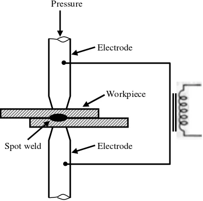
The most widely used pressure welding processes are forge welding and resistance welding. A simple type of forge welding can be illustrated by the familiar blacksmith method of joining
metals by hammering them at a red heat, FIGURE 8-11 Resistance spot welding.
Pressure
Pressure
Electrode
Workpiece
13/36
but now steady pressure exerted by special machinery is generally used. Resistance welding involves heating the metal surfaces to be joined by passing an electric current across them. This is accompanied by mechanical pressure, which results in the intimate union of the two parts (Fig. 8-11).
If the pressure welding is carried out at low temperatures it is known as cold welding. This requires very extensive deformation and very high pressures to break up the oxide films. However, it does not involve much transfer of matter across the interface. The bond results from the interaction of the atomic forces of the metals. New developments in solid phase welding are friction welding, high-energy welding (explosive welding), ultrasonic welding, and diffusion bonding.
Fusion Welding. Fusion welding is accomplished by the fusion of metal to effect the desired union between two pieces. To produce a strong bond, the liquid metal must first wet the surface of the solid metal. Good wetting is favored if the liquid metal and the solid metal show some mutual solubility or form the inter-metallic compounds. The fused metal generally is obtained as a deposit from an external source, called the welding rod or filler rod although, in some cases, the surfaces are merely fused together alone to form the joint. Fusion welding can be accomplished by a variety of methods selected according to the metallurgical and chemical characteristics of the metal to be joined, the required properties of the weld, and the specific conditions of the workpiece. These methods consist of gas welding and electrical welding. In gas welding an oxyacetylene flame is occasionally employed. The oxyacetylene flame may have a neutral, oxidizing, or reducing character, depending on the proportions of acetylene and air, or oxygen, used. This, in turn, depends on the type of metal to be welded but, in general, a neutral flame is most widely used. An extra metal is added from the welding rod, but no fluxes are used.
Electric-arc welding methods include carbon-arc welding, atomic hydrogen welding, inert-arc welding, and multiarc welding. An electric arc is struck between the carbon or metal electrode and the work material to be welded. The intense heat of the arc causes the fusion of the base metal, as
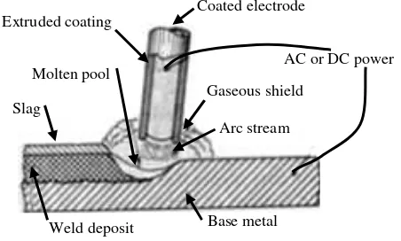
well as of the metal filler rod, in case an additional amount of the metal is needed for the weld. Practically all welding with the metallic arc is done with a shielded arc in which the metallic electrode is covered with a thick layer of fluxing ingredients. The shielding effect is due to the fluxing ingredients, which melt and form a slag covering over the weld and thus are able to protect the molten metal from the air (Fig. 8-12).
For reactive metals arc, multiarc, and atomic hydrogen welding are used. In inert-arc welding (heliinert-arc) either a tungsten or a carbon electrode is used. The inert gas, helium or argon, is fed through a nozzle which surrounds the electrode in the head of the torch and completely protects the arc and also the pool of molten metal from contact with the atmosphere. In atomic hydrogen welding a stream of hydrogen is passed through the arc struck between two tungsten electrodes. The intense heat dissociates molecular hydrogen into atomic hydrogen, which recombines on the metal surface to be welded with the evolution of the same amount of heat as that absorbed during dissociation. This method is used extensively for aluminum welding to prevent its oxidation.
FIGURE 8-12 Arc welding with shielded electrode. Many electrode coatings contain cellulose which, on
decomposition, yields gases, forming a shield.
Coated electrode
AC or DC power
Gaseous shield
Arc stream Slag
Molten pool Extruded coating
14/36
Plasma-arc welding is a further development of the inert-arc welding in which a gas is ionized when passing through the electric arc and impinges on the surface to be welded. Very high temperatures are developed, resulting in the speedy welding of two parts. A recent development in fusion welding is the employment of radiation energy, as in laser and electron beam welding. The essential feature of these processes is that the radiant energy is narrowly focused on the workpiece, and heat is generated only where the focused beam is intercepted. This reduces the possibility of distortion and results in improved weld properties. Using a laser radiation beam, it is then possible to drill very fine holes in diamonds or in other very hard materials. Highly reflective surfaces are not easily welded. In electron beam welding the energy is supplied by the impact of a focused beam of electrons. Operating in a vacuum is an additional advantage with welding metals that are sensitive to contamination from the atmosphere.
Brazing and Soldering. Brazing and soldering are metal-joining processes which use another metal or alloy that has a melting point substantially lower than that of the metal to be joined. In brazing, copper or silver alloys are widely used; in soldering, low-melting alloys of tin and lead are used. Brazing is done at temperatures that are above 535°C but are always lower than the melting point of the metal to be joined. Soldering differs from brazing in that the introduced molten metal has a softening point much lower than that of the brazing alloy. Solders are usually lead—tin alloys of varying composition, but compositions of 50% lead—tin or 60% to 40% lead—tin are most widely employed.
The essential requirements for obtaining good joints in brazing or soldering are proper joint design, preparation of the joint surfaces, fluxing, assembling, heating, and final cleaning. Since there is no melting of the parent metal, the molten brazing alloy either flows between heated surfaces of the joint members or is melted in place between such surfaces. Cleaned surfaces are essential to bring about adhesion of the brazed weld to the parent metal. This adhesion is obtained by using fluxes that dissolve the oxide film on the metal surface and at the same time prevent the oxidation of the metal during preheating. Fluxes should have a melting point below that of the brazing alloy for easy wetting and cleaning of the surfaces before the molten brazing alloy is applied. Fluxes are either acids or compounds that decompose into acidic substances that corrode the metal to be joined. Brazing fluxes are usually mixtures of borax with boric acid or borax with zinc chloride.
8-6 POWDER METALLURGY
Powder metallurgy is the process of producing metallic powders and converting them, sometimes in conjunction with nonmetallic powders, into ingots or finished articles by compacting and sintering. Powder metallurgy is now used extensively whenever porous parts are needed, whenever the parts have intricate shapes that can be easily processed and sintered, whenever the alloy or mixture of metals cannot be made in any other way, or whenever the metals have very high melting points and are therefore difficult to cast and machine. Nearly all commercially used metals can be shaped by the powder technique, which is ideally suited to the preparation of components with a controlled amount of porosity distributed in a specified manner. An organic binder is frequently added during the mixing stage but volatilizes at a low temperature, facilitating the formation of interconnected pores.
15/36
The atomization method is now the major method of manufacture because it can make powders from alloys as well as from pure metals. The method depends on forcing a molten metal through an orifice and then breaking up this stream with a jet of water or gas. The metal particles formed by the jet solidify very rapidly, so that even in air only very superficial oxidation takes place, provided the metal is not too reactive.
Substantial amounts of fine powders quenched at cooling rate of 104 K s−1 or higher can be produced by plasma spraying and centrifugal atomization in helium and also from finely chopped melt spun ribbons. Such powders are characterized by high reactivity when hot pressed and sintered with an other powder forming consolidated products of much higher yield and ultimate tensile strength than that of alloys obtained by more conventional methods. For example, the development of aluminum alloys such as Al— Zn—Mg—Cu through consolidation of atomized pre-alloyed powder produced the material with yield strength as high as 850 MPa (124 ksi) attained after heat treatment. This is considerably higher than the yield strengths of conventional high-strength alloys such as 7001 and 7005 aluminum alloys wrought from ingot. Mechanical alloying has been used to produce complex oxide dispersion strengthened (OD-s) alloys that are difficult or impossible to manufacture by conventional melting and casting technique. By mechanical mixing, ultrafine powders can be blended with fine refractory oxides to form an OD-s alloy. On further attrition in a specific solvent, for example, isopropyl alcohol, further diminution of the particles occurs and the reactivity of the mixture is enhanced.
Compacting and Sinlerlng. The shaping of articles from metallic powders is accomplished by compacting and sintering, the principles of which were discussed in Chapter 6, Section 6-7. The finer the particles, the greater will be the strength of the compact. Usually polydisperse powders of the proper size range give stronger compact and higher sintering rates than monodisperse powders of the same particle size. Powder metals are often compacted in mechanical or hydraulic presses. where a vertical stroke exerts a force to consolidate the loose powder into a shaped green compact. The pressure between two rotating rolls can also be utilized for powder compaction (Fig. 8-13). Hot pressing has been widely used for refractory-type metals and ceramics with high melting points and high hardness and strength. Using the pressure in conjunction with high temperature leads to high densities of the sintered product. Hot pressing is usually carried out in inert graphite or ceramic molds to avoid contamination of the powder mass.
Structures and properties of the sintered materials are determined by residual porosity and permeability. Grain size is second in importance to porosity with respect to uniqueness of structure. The strength of the sintered powder compact is given by
kP p ====α0e−−−−
σ (8-9) where σp= the strength of the porous body
0
α = the strength of the homogeneous material
k = the coefficient dependent on the shape of the pores
P = the porosity
16/36
produced from the beryllium powder, which is compacted and sintered at about 1100°C in an atmosphere of argon or nitrogen.
(a)
(b)
FIGURE 8-13 Compacting and sintering of Mond (carbonyl) nickel powder, size less than 7 µm. (a) Pressed at 40.000 psi (276 MPa), 68.8% density, 413 x. (b) Pressed at 40.000 psi (276 MPa) and sintered 1 h in hydrogen at 1250°,. 87.5%
density, 413 x. Dark spots are the remaining pores.
FERROUS METALS
Ferrous metals cover a wide variety of industrially important products that can be grouped into wrought irons, cast irons, carbon steels, and alloy steels.
8-7 IRON—CARBON EQUILIBRIUM DIAGRAM
Many properties of cast irons and carbon steels, as well as their microstructure, can be explained by reference to the iron—carbon phase equilibrium diagram (Fig. 8-14). Strictly speaking, the diagram refers to the iron—iron carbide system, but the existing phase relationship can be expressed in terms of the percentage carbon content. The diagram is divided into a number of phase fields, each occupied by either a single phase or a mixture of two phases. Curve ABCD is the liquidus line above which there is only
one liquid phase consisting of iron and dissolved carbon. Curve AEPGCH is the solidus
line below which the various iron-carbon compositions are completely solid. The regions between these two lines represent mixtures of solid and liquid.
Both α iron, having a body-centered cubic structure, and γ iron, with face-centered cubic structure, are capable of dissolving certain amounts of carbon, which vary according to temperature. The solid solution of carbon in α iron is called ferrite, whereas the solid solution of carbon in γ iron is called austenite. The terms α and γ iron are also used to designate ferrite and austenite, respectively. Austenite is capable of dissolving far more carbon than ferrite, and it may contain up to 2.11% carbon (point G), whereas ferrite can
only dissolve up to 0.025% carbon (point L). The solubility of carbon changes with the
temperature in both austenite and ferrite in the manner indicated by curves GK for
austenite and LI for ferrite.
The third solid phase existing in the diagram is cementite, which is a compound of composition Fe3C, corresponding to 6.69% by weight carbon. Cementite is hard and brittle, whereas ferrite is relatively soft and malleable.
17/36
occurring under equilibrium conditions. In practice, however, equilibrium is seldom obtained and the critical temperature lines will be shifted to higher positions on heating and to lower positions on cooling. The degree of shift from the equilibrium conditions will depend on the rate of heating or cooling.
FIGURE 8-14 Carbon—iron phase diagram. (Adapted from Metals Handbook, 1973 edition, Vol. 8. )
The diagram also indicates the existing ranges of composition for iron, steel, and cast iron. Compositions up to 0.008% carbon are regarded as commercially pure iron, those from 0.008 to 2% carbon represent steel, and those above 2% carbon represent cast iron. Steels are further subdivided into hypoeutectoid steel up to 0.77% carbon and hypereutectoid steel from 0.77% to 2% carbon (see also Fig. 8-15).
Austenite is not stable below lines A3 (IK) and Acm (GK). For compositions containing less than 0.77% carbon, austenite on cooling begins to transform into ferrite, and the remaining austenite increases its carbon content along the line A3 until point K (0.77% carbon) is reached. For compositions between 0.77% and 2.1% carbon, cementite will separate out and the austenite composition will vary along the line Acm (GK) until again point K is reached. At point K, called the eutectoid, austenite will transform into pearlite,
which is an intimate mixture of ferrite and cementite. This is called the eutectoid transformation, characterized by the decomposition of a solid solution into two different solid phases according to the reaction
1600
|
6.0 1500 −
1400 −
1300 −
1200 −
1100 −
1000 −
900 −
800 −
700 −
600 −
500 −
400 −
300 −
200 −
100 −
0 − |
0.5 1.0 | 1.5 | 2.0 | 2.5 | 3.0 | 3.5 | 4.0 | 4.5 | 5.0 | 5.5 | 6.5 |
Fe
Weight percent carbon
A B
E
1495 1538
F 1394
(γ-Fe)
Austenite G
1154 1148
F Solubility of
graphite in liquid Fe
Cementite
(Fe3C)
Acm
A3
D
2.08 2.11
H
α + Fe3C 738 727 K
L 912 I
α-Fe Ferrite
A1
230 (δ-Fe) P
C
4.30 6.69
0.77
18/36
solid phase A→ solid phase B + solid phase C (8-10)
(austenite) (ferrite) (cementite)
There are three phases, austenite, ferrite, and cementite, existing in equilibrium at the eutectoid point. It follows from the phase rule that the number of degrees of freedom is zero, F = C — P + I = 2 —3 + 1 = 0, and the eutectoid point, like that of the eutectic, is
nonvariant. The eutectoid reaction is one of the most important transformations occurring in the iron—carbon system; it is also found in many other alloy systems.
FIGURE 8-15 Microstructures of carbon steels on slow cooling.
At a temperature of 1148°C, the eutectic transformation (point C) takes place. The
eutectic liquid with 4.30% carbon begins to freeze to a eutectic mixture of austenite and cementite called ledeburite. On further cooling, the eutectic austenite transforms gradually to cementite, and its composition changes along line GK until again the
eutectoid point is reached. Here all the remaining austenite will finally transform to pearlite. Another type of
transformation is the peritectic, which occurs at a temperature of 1495°C (point P). The
peritectic reaction involves the transformation of a liquid phase and a solid phase into another solid phase of different composition according to the reaction
liquid (0.5% C) + δ iron (0.08% C) →γ iron (0.18% C) (8-11) The peritectic reaction affects only the solidification of steels with less than 0.55% carbon, and it is of little practical importance.
Consider a steel containing 0.4% carbon represented on the partial carbon—iron diagram (Fig. 8-15) by line xx. When cooling from the liquid region along line xx, freezing begins
at the liquidus line. Complete solidification of an alloy occurs at the solidus line AG. As
cooling proceeds, no changes occur until line A3 is reached, where the precipitation of ferrite from the solid phase of austemte begins. Further cooling results in an increase in ferrite, whereas the amount of austenite decreases and its composition varies along line
IK. The composition of ferrite varies along line IL reaching a maximum carbon content
of 0.025% at point L. At any point in region ILK, the percentages of austenite and ferrite
can be calculated from the lever rule. For example, at 750°C (point b), austenite contains
0.5% carbon and ferrite contains 0.02% carbon (see the horizontal dashed line b’bb”).
Hence the amount of austenite will be
% 79 % 100 % 48 . 0 % 38 . 0 % 02 . 0 % 5 . 0 % 02 . 0 % 4 . 0 ==== ×××× ==== −−−− −−−−
and that of ferrite will be 100% — 79% = 21%.
(a)
(b)
(c)
(d)
(e)
(f)
Pearlite Pearlite
Cementite
Frrite-α and
γ-austenite Frrite-α I A3 a X d
b’ b b” c
γ-Austenite and cementite
Pearlite and cementite Frrite-α and
pearlite
γ-Austenite
L K
c’
c c” f
0.02
X
19/36
At the eutectoid temperature of 727°C, the remaining austenite undergoes transformation to pearlite, which consists of 88.8% ferrite and 11.2% cementite. The composition of the pearlite can be found by considering the section between points L and M divided by
point K as shown in Fig. 8-14.
Further cooling below the eutectoid temperature causes practically no further changes in the microstructure of the steel, since the solubility of carbon in ferrite (line LN) changes relatively very little. At any point below 727°C the microstructure of the steel will consist of a pearlite matrix in which primary crystals of ferrite are embedded. The amounts of the microconstituents at point c (the horizontal dashed line c’cc’’) can be calculated from lever rule,
% 27 . 49 % 100 % 019 . 0 % 77 . 0 % 40 . 0 % 77 . 0 ferrite of
amount ×××× ====
−−−− −−−− ==== % 73 . 50 % 100 % 019 . 0 % 77 . 0 % 019 . 0 % 40 . 0 pearlite of
amount ×××× ====
−−−− −−−− ====
where 0.019% is the carbon content of ferrite at point c’.
It can also be seei that a steel of the eutectoid composition (0.77% C) will consist only of pearlite. whereas a steel with a carbon content larger than 0.77% will consist of pearlite and cementite. The microstructures of 0.4% and 1.0% carbon steels at various points of the carbon—iron phase diagram are given in Fig. 8-15 by sketches a—f.
8-8 TIME—TEMPERATURE TRANSFORMATIONS
The iron—carbon equilibrium diagram shows only the phases and the resulting microstructure corresponding to equilibrium conditions. In practice, however, equilibrium is seldom obtained, since the cooling rates are usually much higher than those necessary to maintain equilibrium. As the cooling rate increases, the experimentally observed transformation temperatures are lowered, and metastable (nonequilibrium) phases may be formed. For example, at very high rates of cooling in the steel range a metastable phase called martensite can develop which, of course, has no place in the equilibrium diagram. The presence of certain alloying elements also affects considerably the transformation range of the various phases and may result in a completely new diagram.
The eutectoid reactions are also greatly affected by the rate of cooling. The course of the eutectoid transformation may be represented for each temperature by a series of isothermal curves. These are obtained by plotting the percentage of austenite transformed to pearlite versus time for any specific temperature (Fig. 8-16).
FIGURE 8.16 Isothermal reaction curves (0.77% carbon steel).
(J. Wulff et al. Metallurgy for Engineers, John Wiley & Sons, Inc., New York,1952.)
A series of such isothermal reaction curves can be used to plot a time—temperature transformation (TTT) diagram, as shown in Fig. 8-17.
A us te ni te tr an sf or m at io n % Time, sec 100
95 −
50 −
5 − |
10 100 | 1000
500oC
595oC 705oC
3 2 1
20/36
FIGURE 8-17 Temperature-time transformation diagram or Bain (S) curves. (J. Wulff
et.aI.Metallurgy for Engineers, John Wiley & Sons, Inc., New York, 1952.)
The resulting curve is known as the Baine or S curve. It is seen from the S curve that the greatest speed of transformation corresponds to the nose of the knee of the S curve. The rate of transformation decreases below the temperature of the nose, owing to the slowing down of atomic diffusion. whereas above this temperature it decreases because of the increased stability of austenite.
Above the critical temperature A1, austenite (Fig. 8-18a) will be stable and there will be no transformation to pearlite. In addition to the variations in the rate of transformation with temperature, there are variations in the structure of the transformation products. Transformations at temperatures between approximately 727 and 535°C result in the characteristic lamellae microstructure of pearlite (Fig. 8-18b). At a temperature just below A1, nucleation of cementite from austenite will be very slow, but diffusion and growth of nuclei will proceed at maximum speed, so that there will be few large lamellae and the pearlite wIl be coarse. However, as the transformation temperature is lowered, the perlite becomes more and more fine. Transformation at temperatures between 535 and 260°C results in the formation of bainite consisting, like pearlite, of a ferrite matrix in which particles of cementite are embedded. The individual particles are much finer than in pearlite, and bainite cannot be resolved by ordinary microscopic examination. Bainite has an acicular microstracture, and It is harder than pearlite and tougher than martensite.
(a)
(b) (c)
FIGURE 8-18 (a) Austenitic microstructure In steel (18% Cr-8% Ni), x250. (b) Pearlite microstructure in 0.77% C steel, X 1300. (c) Martensitic microstructure
in carbon steel x1500.
Martensite (Fig. 8-18c) is regarded as a supersaturated solid solution of carbon in ferrite, but it has a body-centered tetragonal structure with carbon atoms located interstitially. Martensite is formed by the diffusionless transformation of austenite on rapid cooling to a temperature about 260°C, designated as Ms. Since the martensite transformation is accompanied by an increase in volume, the temperature must be lowered in order to
T
em
pe
ra
tu
re
oC
Pearlite 705
−
595
−
535−
Ms
Mf
Bainite A1 (727oC)
|
10 100 | 1000 | 10000 |
Time, sec
3 3’ 3” 2 2’ 2”
1 1’ 1”
21/36
cause the transformation to proceed to completion. Finally, at a temperature designated as Mf, austenite will be wholly transformed to martensite. The starting temperature of the martensite transformation, Mf, and the finishing temperature, Ms, are represented on the TTT diagram as horizontal lines (Figs. 8-17 and 8-19). The positions of these lines vary somewhat with the carbon content of the steel. The martensite transformation differs from the other transformations in that it is not time dependent and occurs almost instantaneously; the proportion of austenite transformed depends only on the temperature to which it is cooled.
Martensite, as formed in steels, is distinguished by very high hardness, but it also has a tendency to brittleness. The hardness depends on the carbon content; steels containing 0.15% carbon or less do not harden appreciably on quenching. With higher carbon contents above 0.2% the martensite is so hard that the steel is brittle unless properly tempered.
8-9 CONTINUOUS COOLING TRANSFORMATIONS
During heat treatment operations, the steel is continuously cooled from above the critical temperature range (A3) to room temperature. Thus the transformation of austenite does not occur isothermally, as assumed in the TTT diagram, but over a certain period during which the temperature drops from, say, T1 to T2. Thus the average temperature of the transformation (T1 + T3)/2 will be lower during continuous cooling than during isothermal cooling and, consequently, the transformation of austenite will be somewhat delayed. These will cause the S curve to be shifted toward lower temperatures and longer transformation times during continuous cooling as compared to those of the TTT curve (Fig. 8-19).
FIGURE 8-19 Continuous
cooling transformation
curves for the eutectoid steel
(0.77% C). Dashed curves
are TTT curves, whereas
solid curves shifted to the
right and down are
continuous cooling curves.
Cooling curve
B
results in
the microstructure
composed of pearlite and
martensite. Curve
D
corresponds to cooling rates
during annealing, whereas
curve
C
corresponds to
cooling rates during
normalizing. Cooling rates
(curve
A
) higher than the
critical cooling rate result in
martensitic structure, or in
bainite (austempering)
structure, or martempering,
according to the temperature
of quenching.
22/36
The minimum cooling rate required to produce martensite in a given steel is determined by the position of the nose of the S curve. The cooling rate required to avoid the nose of the S curve is called the critical cooling rate; any cooling rate (curve A) greater than that
will result in complete transformation of an austenite to martensite. If the cooling rate is slower than the critical cooling rate, the cooling curve (B) will intersect the pearlite zone. This results in the transformation of some austenite to pearlite, and only the remaining austenite will transform to martensite when the M, temperatures are reached. The microstructure of such a steel will then be composed of fine pearlite and martensite. Cooling curves C and D show that at such cooling rates austenite will transform completely to pearlite before any martensite can be formed.
In transformation of hypoeutectoid (C <0.77%) and hypereutectoid (C > 0.77%) steels, austenite transformation always begins with separation of the proeutectoid phase, either ferrite or cementite, the amount depending on the carbon content of the steel. This results in nucleation of the proeutectoid ferrite in hypoeutectojd steels or the procutectoici cementite in hypereutectoid steels at the grain boundaries of the austenite, as illustrated in Fig. 8-15. On further cooling the amount of ferrite or cementite increases until the eutectoid temperature is reached at which the austenite will have the eutectoid composition of 0.77% C. Any further cooling will result in the transformation of austenite to pearlite, so the microstructure will be the proeutectoid ferrite and pearlite. On quenching from the austenite range, the proeutectoid ferrite may not be able to form completely and austenite of higher C content will change directly to martensite (Fig. 8-20).
FIGURE 8-20 Continuous cooling transformation curves in proeutectoid steel (C less than 0.77%).
The diagram also shows that bainite cannot be obtained in any appreciable quantity by continuous cooling to room temperature because it is sheltered by an overhanging pearlite nose. Thus austenite will be completely transformed to pearlite before the temperature of the bainite formation is reached. The bainite microstructure can be obtained only by cooling the steel from the austenite range to a temperature between 535 and 260°C at a rate greater than the critical cooling rate. This is accomplished in practice by quenching the steel in a bath of molten salt or a low-melting alloy and holding it at this temperature for some definite time. Then the steel is removed from the quenchant and cooled to room temperature.
Austenite A3
A1 A + F
A + F + C
Ferrite + Cementite
MS
50% Martensite
|
10 10| 2 10| 3 10| 4 10| 5 10| 6 Time, sec
800 −
600 −
400 −
200 −
T
em
pe
ra
tu
re
23/36
8-10 HEAT TREATMENT OF CARBON STEELS
Carbon steels are those ferrous alloys in which carbon is the main element used to control their mechanical properties. Other elements, such as aluminum, boron, chromium, cobalt, nickel, titanium, tungsten, vanadium, and zirconium, are also commonly found in carbon steels, but their content is not specified and their presence is due to manufacturing processes. In addition, carbon steels contain up to 1.65% manganese, 0.60% silicon, and 0.4% copper.
Carbon steels are divided into three classes, according to their carbon content. Low-carbon steels contain from 0.08 to 0.35% Low-carbon, medium-Low-carbon steels contain from 0.35 to 0.50% carbon, and high-carbon steels have a carbon content greater than 0.5%.
Annealing and Normalizing. Steel, whether wrought or cast, is in a more or less coarsely granular condition. Heat treatment is necessary, particularly for cast steels, to break up the coarse structure and bring about refinement of grain size as well as uniform distribution of the constituents present. This is accomplished by annealing and normalizing. Full annealing consists of heating the steel to a temperature above its critical range, holding it there for a sufficient period of time, and slowly cooling it (usually in the furnace) to obtain an equilibrium structure. Heating above the upper critical temperature causes pearlite and any excess of cementite or ferrite to transform to austenite. This is known as austenitizing. Hypoeutectoíd steels are heated above the upper critical temperature (A3 line), whereas hypereutectoid steels are heated only above the lower critical temperature (A1 line), as seen in Fig. 8-21. Annealed hypereutectoid steels contain cementite and can never really be soft, but they are in the best possible condition for machining. Other heat treatment processes in which the steel is heated below the lower critical temperature are called stress relief and spheroidizing, in contrast to full annealing, which always consists of heating above the critical temperature.
FIGURE 8-21 Heat treatment temperatures for carbon steels. (Metals Handbook, 1948 edition, American Society for Metals, Metals Park, Ohio.)
Spheroidizing is the formation of spheroids, which are embedded in a matrix of ferrite, from cementite. Particles are large enough to be readily visible under the light microscope. Martensite, bainite, and even pearlite can be changed to this structure, which results in considerable softening of the steel. Normalizing consists of heating the steel above its upper critical temperature, and then cooling it in still air. It differs from full annealing in that the rate of cooling is more rapid and there is no extended soaking period. Normalizing produces a uniform structure and refines the grain size of the steel, which may have been unduly coarsened at the forging temperature. If a steel is too soft
T
em
pe
ra
tu
re
oC
Fine grain temperature range
Normalizing Hardening
Annealing Fine grain
temperature range
A1
Cementite + Pearlite A3
Ferrite + Austenite
Spheroidizing Ferrite +
Pearlite Tempering 950 −
900
−
850 −
800 −
750 −
700 −
650 −
24/36
and ductile for machining, a normalizing process may achieve the required strength and ductility. The process is faster than full annealing and is often more suitable for producing a satisfactory steel.
Quenching. The hardening of steel requires the formation of martensite. This is accomplished by heating to a temperature high enough for steel to become austenitic, then cooling fast enough, usually by quenching in water or oil, to secure complete transformation to martensite. The composition of the steel to be hardened, the quenching technique used, and the design for heat treatment are all very important factors affecting the properties of the final product. Sharp corners, reentrant angles, and drastic changes in thickness should be avoided whenever possible in order to keep temperature gradients at a minimum throughout the specimen. In the fully quenched state steel containing more than 0.2% carbon has such low ductility as to render the material useless for engineering applications, and it must be softened to some desired degree by tempering before use.
Tempering. Tempering is a controlled heat treatment consisting of reheating martensite, which is extremely brittle when produced during quenching of carbon steel. To improve its properties and to impart greater toughness, the quenched steel is subject to tempering by heating to various temperatures below the critical temperature A1. Three stages of tempering are distinguished. In the first stage the quenched steel is heated to a temperature of 80 to 160°C (176 to 320°F), during which martensite loses some ε -carbide. This latter separates into very small particles and becomes less tetragonal. During the second stage. 230 to 280°C (446 to 536°F), any retained austenite transforms to bainite, and large dimensional changes occur. Finally, in the third stage, 260 to 360°C (500 to 680°F), ε-carbide changes to cementite platelets, producing a structure of ferrite and cementite. This is accompanied by a marked softening of the steel. The ε-carbide particles are extremely small in size, but they can be identified with the aid of the electron microscope. The ε-carbide is a closely packed hexagonal structure of composition of about Fe5C2. The tempered steel becomes much more ductile, but at the same time, there is an unavoidable loss of hardness.
In the process called martempering the steel is quenched to a temperature just above the martensite formation Ms and held there long enough to obtain the uniform temperature, but not long enough for bainite to form (see Fig.8-19). Then the steel is cooled in air. The resulting microstructure is martensitic, but the steel shows an improved ductility, and no tempering is necessary because martensite has been formed without the production of high internal stresses.
Hardenablllty. Hardenability is an index of the depth to which a given steel will harden when quenched in a particular manner, or it is the ease with which martensite can be produced in the steel. Hardenability is determined by a highly standardized test such as the Jominy end-quench test, but it is best assessed by the diameter of the largest steel cylinder that can be hardened all the way to its center by water quenching.
During quenching, a piece of steel will cool more rapidly at the surface than in the interior. This may cause the interior of the piece to be hardened to a lesser degree than the surface since, in a less rapidly cooled portion, some pearlite may be formed before martensite. For a piece of steel to be hardenable throughout, the critical cooling rate should be such that martensite forms before any pearlite has a chance to appear. This can be achieved by making the cross section very thin or by retarding the transformation of austenite to pearlite. This latter is equivalent to displacement of the S curve to the right on the TTT diagram so that the gate at the nose is considerably widened.
25/36
piec